
Owner's Manual
Page 8
... USER DEFINE screen 189 SAVE screen 192 LOAD screen 195 FADER ASSIGN screen 197 SECURITY screen 198 SYS/W.CLOCK function 199 WORD CLOCK screen 199 MIXER SETUP screen 200 CASCADE screen 204 HA (Head Amp) screen 206 OUTPUT PORT ATT (Output port attenuation) screen 207 DITHER screen 207 HA LIBRARY screen... CH VIEW (Channel view) screen 245 SIGNAL FLOW screen 247 FADER VIEW screen 249 CH COPY (Channel copy) screen 249 OUTPUT CH LIBRARY screen 251 8 PM5D/PM5D-RH Owner's Manual Table of Contents -
... USER DEFINE screen 189 SAVE screen 192 LOAD screen 195 FADER ASSIGN screen 197 SECURITY screen 198 SYS/W.CLOCK function 199 WORD CLOCK screen 199 MIXER SETUP screen 200 CASCADE screen 204 HA (Head Amp) screen 206 OUTPUT PORT ATT (Output port attenuation) screen 207 DITHER screen 207 HA LIBRARY screen... CH VIEW (Channel view) screen 245 SIGNAL FLOW screen 247 FADER VIEW screen 249 CH COPY (Channel copy) screen 249 OUTPUT CH LIBRARY screen 251 8 PM5D/PM5D-RH Owner's Manual Table of Contents -
Owner's Manual
Page 10
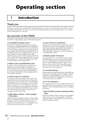
...Thank you for effect return. As input channels, it provides 48 monaural channels, four stereo channels, and four stereo channels for purchasing the Yamaha PM5D digital mixing console. You can be linked. Effects such as reverb, delay, multiband compressor, and various modulation effects can be routed via a...output. ❏ Scene memories and libraries Mix parameters and internal effect settings can operate the fader, pan, cue, and on an analog mixer. AD cards, DA cards, or digital I /O card expansion The rear panel provides four slots in which separately sold mini-YGDAI cards can...
...Thank you for effect return. As input channels, it provides 48 monaural channels, four stereo channels, and four stereo channels for purchasing the Yamaha PM5D digital mixing console. You can be linked. Effects such as reverb, delay, multiband compressor, and various modulation effects can be routed via a...output. ❏ Scene memories and libraries Mix parameters and internal effect settings can operate the fader, pan, cue, and on an analog mixer. AD cards, DA cards, or digital I /O card expansion The rear panel provides four slots in which separately sold mini-YGDAI cards can...
Owner's Manual
Page 45
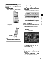
... that share the same fader. ❏ Using vertical pairing Here's how to the subsequently-pressed channel. Now you press the [SEL] keys. PM5D/PM5D-RH Owner's Manual Operating section 45 Hint The copy-source channel is turned on in the UTILITY function PREFERENCE 1 screen (➥ p.187). PAIR...disabling pairing Monaural input channels can be paired to link their parameters linked except for head amp, delay, pan, attenuation, and phase. MIXER SETUP VERTICAL PAIR button Vertical pair Hint Input channels that you can return to "horizontal pair mode" by the order in the PAIR MODE...
... that share the same fader. ❏ Using vertical pairing Here's how to the subsequently-pressed channel. Now you press the [SEL] keys. PM5D/PM5D-RH Owner's Manual Operating section 45 Hint The copy-source channel is turned on in the UTILITY function PREFERENCE 1 screen (➥ p.187). PAIR...disabling pairing Monaural input channels can be paired to link their parameters linked except for head amp, delay, pan, attenuation, and phase. MIXER SETUP VERTICAL PAIR button Vertical pair Hint Input channels that you can return to "horizontal pair mode" by the order in the PAIR MODE...
Owner's Manual
Page 57
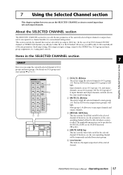
...will be affected when a scene is on /off for the selected channel. E Level meter This indicates the input/output level of a conventional analog mixer. This section controls the channel that was last selected by pressing its [SEL] key. (In the case of an ST IN channel, FX ...be temporarily excluded from mute groups. Mute groups 1-8 allow you to mute groups 1-8. The key LED for the assigned DCA group(s) will light. PM5D/PM5D-RH Owner's Manual Operating section 57 it corresponds to control input channels and output channels. The key LED for the assigned mute group(s) will light...
...will be affected when a scene is on /off for the selected channel. E Level meter This indicates the input/output level of a conventional analog mixer. This section controls the channel that was last selected by pressing its [SEL] key. (In the case of an ST IN channel, FX ...be temporarily excluded from mute groups. Mute groups 1-8 allow you to mute groups 1-8. The key LED for the assigned DCA group(s) will light. PM5D/PM5D-RH Owner's Manual Operating section 57 it corresponds to control input channels and output channels. The key LED for the assigned mute group(s) will light...
Owner's Manual
Page 79
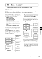
... 10 HA #1 Scene memory 10 PM5D/PM5D-RH Owner's Manual Operating section 79 A scene contains the settings of the panel controls (except for a certain scene, recalling that supports the special protocol (e.g., Yamaha AD8HR or AD824). For example if...PM5D model) as well as the settings of the functions and screens listed below. • INPUT function settings • OUTPUT function settings • EFFECT PARAM screen settings • GEQ PARAM screen settings • SELECTIVE RECALL screen (SCENE function) settings • FADE TIME screen (SCENE function) settings • MIXER...
... 10 HA #1 Scene memory 10 PM5D/PM5D-RH Owner's Manual Operating section 79 A scene contains the settings of the panel controls (except for a certain scene, recalling that supports the special protocol (e.g., Yamaha AD8HR or AD824). For example if...PM5D model) as well as the settings of the functions and screens listed below. • INPUT function settings • OUTPUT function settings • EFFECT PARAM screen settings • GEQ PARAM screen settings • SELECTIVE RECALL screen (SCENE function) settings • FADE TIME screen (SCENE function) settings • MIXER...
Owner's Manual
Page 93
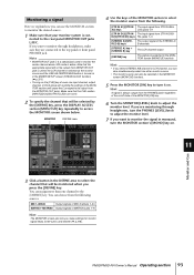
... to be selected by the [DEFINE] key, press the DISPLAY ACCESS section [MON/CUE] key repeatedly to access the MONITOR screen shown below. PM5D/PM5D-RH Owner's Manual Operating section 93 MIX 1-MIX24 Output signals of MIX channels 1-24 MATRIX1-MATRIX8 Output signals of the on . Hint A signal...]/[2TR IN The input signal from the following sources. If you are monitoring through headphones, make settings for monitor signal delay, insert-out/in the MIXER SETUP screen (SYS/W.CLOCK function) (➥ p.201). • Turning on the [CUE] key of even one input channel, output channel, or...
... to be selected by the [DEFINE] key, press the DISPLAY ACCESS section [MON/CUE] key repeatedly to access the MONITOR screen shown below. PM5D/PM5D-RH Owner's Manual Operating section 93 MIX 1-MIX24 Output signals of MIX channels 1-24 MATRIX1-MATRIX8 Output signals of the on . Hint A signal...]/[2TR IN The input signal from the following sources. If you are monitoring through headphones, make settings for monitor signal delay, insert-out/in the MIXER SETUP screen (SYS/W.CLOCK function) (➥ p.201). • Turning on the [CUE] key of even one input channel, output channel, or...
Owner's Manual
Page 132
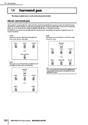
... Operating section 18 Surround pan 18 Surround pan This chapter explains how to use the mouse, the CURSOR keys, or the MIX encoders etc.) The PM5D lets you choose from the following three surround modes, depending on the number of rear center. Front L Center Front R Subwoofer Rear (surround) • 5.1ch This... left and right rear, front center, and subwoofer. About surround pan "Surround pan" is functionality that, when used with the addition of channels in the MIXER SETUP screen (SYS/W.CLOCK function) or SURR SETUP screen (MATRIX/ST function).
... Operating section 18 Surround pan 18 Surround pan This chapter explains how to use the mouse, the CURSOR keys, or the MIX encoders etc.) The PM5D lets you choose from the following three surround modes, depending on the number of rear center. Front L Center Front R Subwoofer Rear (surround) • 5.1ch This... left and right rear, front center, and subwoofer. About surround pan "Surround pan" is functionality that, when used with the addition of channels in the MIXER SETUP screen (SYS/W.CLOCK function) or SURR SETUP screen (MATRIX/ST function).
Owner's Manual
Page 142
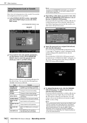
...a password has been specified, a window will be disabled. Input the password and click the OK button to lose the system password. 142 PM5D/PM5D-RH Owner's Manual Operating section You will appear for the selected parameters. LOCK PARAMETER SELECT area SECURITY Note As long as the PARAMETER LOCK button... for the selected item. When you click a button, a check mark will return to the screen in step 3, an indication of the MIXER SETUP screen and CASCADE screen Changes to the word clock setting Changes to dither-related settings Changes to the input patch settings (and names) Changes...
...a password has been specified, a window will be disabled. Input the password and click the OK button to lose the system password. 142 PM5D/PM5D-RH Owner's Manual Operating section You will appear for the selected parameters. LOCK PARAMETER SELECT area SECURITY Note As long as the PARAMETER LOCK button... for the selected item. When you click a button, a check mark will return to the screen in step 3, an indication of the MIXER SETUP screen and CASCADE screen Changes to the word clock setting Changes to dither-related settings Changes to the input patch settings (and names) Changes...
Owner's Manual
Page 143
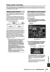
...slaves (➥ p.204). • If you want to cascade-connect a PM5D with a Yamaha DM2000 or 02R96, connect the CASCADE OUT connector of the DM2000/02R96 to the CASCADE IN connector of the PM5D. MIXER SETUP If you want operations such as scene store/recall and cue/ solo to... be linked. If you want to cascade-connect the PM5D with an external mixer (such as the Yamaha DM2000/02R96). CASCADE MODE area BI-DIRECTION button Other functions When multiple PM5D units are cascadeconnected. To cascade-connect two PM5D units, connect the CASCADE IN connectors and CASCADE OUT ...
...slaves (➥ p.204). • If you want to cascade-connect a PM5D with a Yamaha DM2000 or 02R96, connect the CASCADE OUT connector of the DM2000/02R96 to the CASCADE IN connector of the PM5D. MIXER SETUP If you want operations such as scene store/recall and cue/ solo to... be linked. If you want to cascade-connect the PM5D with an external mixer (such as the Yamaha DM2000/02R96). CASCADE MODE area BI-DIRECTION button Other functions When multiple PM5D units are cascadeconnected. To cascade-connect two PM5D units, connect the CASCADE IN connectors and CASCADE OUT ...
Owner's Manual
Page 144
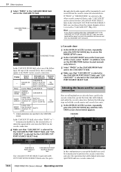
... how to select the buses used for the CASCADE IN PORT SELECT field. PM5D Cascade disabled another PM5D CASCADE IN, SLOT 4, SLOT 3/4, SLOT1-4 [CH1-8], SLOT 1-4 [CH9-16] CASCADE IN Not possible Possible*1 DM2000 /02R96 YAMAHA DM2000 or 02R96 CASCADE IN MIXER [30BUS] A mixer other than the above (maximum 16 bus) SLOT 4 *1. In the CASCADE OUT...
... how to select the buses used for the CASCADE IN PORT SELECT field. PM5D Cascade disabled another PM5D CASCADE IN, SLOT 4, SLOT 3/4, SLOT1-4 [CH1-8], SLOT 1-4 [CH9-16] CASCADE IN Not possible Possible*1 DM2000 /02R96 YAMAHA DM2000 or 02R96 CASCADE IN MIXER [30BUS] A mixer other than the above (maximum 16 bus) SLOT 4 *1. In the CASCADE OUT...
Owner's Manual
Page 150
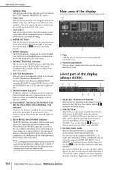
...on , the LCR indicator is displayed here. I TB/OSC/DIMM indicator If talkback, oscillator, or dimmer are received (in the SYS/W.CLOCK function MIXER SETUP screen the BUS SETUP setting STEREO B is set to select TO MATRIX mode this indicates "TO MATRIX." If more than REMOTE. When RS422/... encoders can also click the / buttons to switch between "SEND" and "MASTER." If both the encoders and the faders, you select MIX SEND 150 PM5D/PM5D-RH Owner's Manual Reference section Lower part of the display (always visible) 123 7 456 8 A SELECTED CH (Selected channel) Indicates the type and ...
...on , the LCR indicator is displayed here. I TB/OSC/DIMM indicator If talkback, oscillator, or dimmer are received (in the SYS/W.CLOCK function MIXER SETUP screen the BUS SETUP setting STEREO B is set to select TO MATRIX mode this indicates "TO MATRIX." If more than REMOTE. When RS422/... encoders can also click the / buttons to switch between "SEND" and "MASTER." If both the encoders and the faders, you select MIX SEND 150 PM5D/PM5D-RH Owner's Manual Reference section Lower part of the display (always visible) 123 7 456 8 A SELECTED CH (Selected channel) Indicates the type and ...
Owner's Manual
Page 183
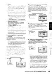
... field at right. Note • When storing a DME scene from the PM5D's screen, you can only store by overwriting an existing scene on the component. This method allows bi-directional transfer of the MIXER SETUP screen (SYS/W.CLOCK function), you click the / buttons located at left... and right to the DME. CASCADE OUT connector DME64N CASCADE IN connector PM5D 4 Uni-directional connection using slot input/output. In the ...
... field at right. Note • When storing a DME scene from the PM5D's screen, you can only store by overwriting an existing scene on the component. This method allows bi-directional transfer of the MIXER SETUP screen (SYS/W.CLOCK function), you click the / buttons located at left... and right to the DME. CASCADE OUT connector DME64N CASCADE IN connector PM5D 4 Uni-directional connection using slot input/output. In the ...
Owner's Manual
Page 184
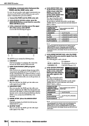
... the DME. F OUTPUT PORT Here you will use for audio signal transmission/reception between the PM5D and the DME series unit, and to initiate communication, proceed as follows. If necessary, click the MIXER SETUP button to be selected here will depend on , a program change the port you can... Owner's Manual Reference section Since this button is on the port that is currently selected for cascade input (MIXER SETUP screen CASCADE IN PORT SELECT field), as follows. 1 Connect the PM5D and the DME series unit. 2 In the DISPLAY ACCESS section, press the [MIDI/REMOTE] key several times to ...
... the DME. F OUTPUT PORT Here you will use for audio signal transmission/reception between the PM5D and the DME series unit, and to initiate communication, proceed as follows. If necessary, click the MIXER SETUP button to be selected here will depend on , a program change the port you can... Owner's Manual Reference section Since this button is on the port that is currently selected for cascade input (MIXER SETUP screen CASCADE IN PORT SELECT field), as follows. 1 Connect the PM5D and the DME series unit. 2 In the DISPLAY ACCESS section, press the [MIDI/REMOTE] key several times to ...
Owner's Manual
Page 198
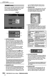
...password. If the system password has been set . As long as the PARAMETER LOCK button (2) is a temporary password (maximum of the MIXER SETUP screen and the CASCADE screen WORD CLOCK SETUP Changes in the word clock setting DITHER Changes in which editing will be disabled can be... the entire memory of differing levels can be specified to represent the characters of eight characters) for the system password. Two passwords of the PM5D (➥ p.147). If a password has been specified, asterisks (*) will be displayed to allow locking and unlocking. If the console password ...
...password. If the system password has been set . As long as the PARAMETER LOCK button (2) is a temporary password (maximum of the MIXER SETUP screen and the CASCADE screen WORD CLOCK SETUP Changes in the word clock setting DITHER Changes in which editing will be disabled can be... the entire memory of differing levels can be specified to represent the characters of eight characters) for the system password. Two passwords of the PM5D (➥ p.147). If a password has been specified, asterisks (*) will be displayed to allow locking and unlocking. If the console password ...
Owner's Manual
Page 200
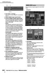
...connected. (This setting can make settings that share the same fader (1/25, 2/26 ...) will be paired. • VERTICAL PAIR If this button is connected. MIXER SETUP 1 2 A PAIR MODE Select one of the following two methods by which a digital I /O card, in sets of two channels. H EMPHASIS STATUS This... is applied to 24 pairs (48 channels). The sampling rate will be assigned to vertical pair mode, new numbers will change 200 PM5D/PM5D-RH Owner's Manual Reference section Hint The graphic below the buttons will be converted for slots in which input channels will be handled ...
...connected. (This setting can make settings that share the same fader (1/25, 2/26 ...) will be paired. • VERTICAL PAIR If this button is connected. MIXER SETUP 1 2 A PAIR MODE Select one of the following two methods by which a digital I /O card, in sets of two channels. H EMPHASIS STATUS This... is applied to 24 pairs (48 channels). The sampling rate will be assigned to vertical pair mode, new numbers will change 200 PM5D/PM5D-RH Owner's Manual Reference section Hint The graphic below the buttons will be converted for slots in which input channels will be handled ...
Owner's Manual
Page 202
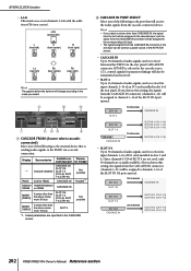
... (channels 1-32) will receive the audio signals from another PM5D CASCADE IN, SLOT 3/4, SLOT 1-4 [CH1-8], SLOT 1-4 [CH9-16] CASCADE IN Not possible Possible*1 DM2000 YAMAHA DM2000 /02R96 or 02R96 CASCADE IN MIXER [30BUS] A mixer other than the above (maximum 30 bus) SLOT 3/4, SLOT... 1-4 [CH1-8], SLOT 1-4 [CH9-16] Not possible MIXER [16BUS] A mixer other than the above (maximum 16 bus) SLOT 4 *1. ...
... (channels 1-32) will receive the audio signals from another PM5D CASCADE IN, SLOT 3/4, SLOT 1-4 [CH1-8], SLOT 1-4 [CH9-16] CASCADE IN Not possible Possible*1 DM2000 YAMAHA DM2000 /02R96 or 02R96 CASCADE IN MIXER [30BUS] A mixer other than the above (maximum 30 bus) SLOT 3/4, SLOT... 1-4 [CH1-8], SLOT 1-4 [CH9-16] Not possible MIXER [16BUS] A mixer other than the above (maximum 16 bus) SLOT 4 *1. ...
Owner's Manual
Page 205
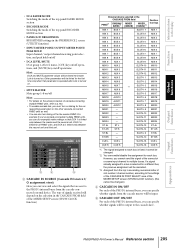
...*1. E CASCADE OUT ON/OFF For each bus. SLOT4- 9 MIX22 - You can (for each of the PM5D's internal buses, you cannot send the signal of the MIXER SETUP screen (SYS/W.CLOCK function) External device selected in the CASCADE FROM field of the same slot or same ... for example) make settings so that are sent to multiple buses. Other parameters will depend on the selection in the CASCADE FROM field PM5D*1 DM2000/ 02R96*1 MIXER [30BUS] MIXER [16BUS]*2 MIX 1 BUS 1 SLOT4- 1 MIX 2 BUS 2 SLOT4-2 MIX 3 BUS 3 SLOT4-3 MIX 4 BUS 4 SLOT4-4 MIX 5 BUS 5 SLOT4-5 MIX 6 BUS ...
...*1. E CASCADE OUT ON/OFF For each bus. SLOT4- 9 MIX22 - You can (for each of the PM5D's internal buses, you cannot send the signal of the MIXER SETUP screen (SYS/W.CLOCK function) External device selected in the CASCADE FROM field of the same slot or same ... for example) make settings so that are sent to multiple buses. Other parameters will depend on the selection in the CASCADE FROM field PM5D*1 DM2000/ 02R96*1 MIXER [30BUS] MIXER [16BUS]*2 MIX 1 BUS 1 SLOT4- 1 MIX 2 BUS 2 SLOT4-2 MIX 3 BUS 3 SLOT4-3 MIX 4 BUS 4 SLOT4-4 MIX 5 BUS 5 SLOT4-5 MIX 6 BUS ...
Owner's Manual
Page 216
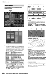
... depending on whether the USE AS STEREO BUS button or the USE AS CENTER BUS button is turned on in the STEREO B section of the MIXER SETUP screen (➥ p.201). MONITOR 1 2 ❏ If the USE AS STEREO BUS button is on Monitor source ST A ST B LCR L STEREO A L - STEREO A R C - STEREO B... MATRIX bus 1-8 output signal 3 4 5 A MONITOR SOURCE Selects the source that will occur when the button is shown in the box below. 216 PM5D/PM5D-RH Owner's Manual Reference section Use the knob to specify the delay time (0-1000 msec), and use an external switch connected to the GPI IN...
... depending on whether the USE AS STEREO BUS button or the USE AS CENTER BUS button is turned on in the STEREO B section of the MIXER SETUP screen (➥ p.201). MONITOR 1 2 ❏ If the USE AS STEREO BUS button is on Monitor source ST A ST B LCR L STEREO A L - STEREO A R C - STEREO B... MATRIX bus 1-8 output signal 3 4 5 A MONITOR SOURCE Selects the source that will occur when the button is shown in the box below. 216 PM5D/PM5D-RH Owner's Manual Reference section Use the knob to specify the delay time (0-1000 msec), and use an external switch connected to the GPI IN...
Owner's Manual
Page 243
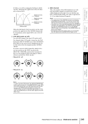
...functions If CSR is set to 100%, turning the PAN knob ([PAN] encoder) will change as the STEREO A bus.) Output functions Input functions Appendices PM5D/PM5D-RH Owner's Manual Reference section 243 If you have selected a MIX channel for which LCR is on, you can also use the [PAN] encoder...appropriately. (In this turns LCR mode on /off . C LCR (LCR mode on /off ) For each MIX channel, this case, the STEREO B bus is in the MIXER SETUP screen (SYS/ W.CLOCK function) (➥ p.201). Signal level L C R [PAN] encoder Signal sent to the C channel Signal sent to the L channel Signal ...
...functions If CSR is set to 100%, turning the PAN knob ([PAN] encoder) will change as the STEREO A bus.) Output functions Input functions Appendices PM5D/PM5D-RH Owner's Manual Reference section 243 If you have selected a MIX channel for which LCR is on, you can also use the [PAN] encoder...appropriately. (In this turns LCR mode on /off . C LCR (LCR mode on /off ) For each MIX channel, this case, the STEREO B bus is in the MIXER SETUP screen (SYS/ W.CLOCK function) (➥ p.201). Signal level L C R [PAN] encoder Signal sent to the C channel Signal sent to the L channel Signal ...
Owner's Manual
Page 244
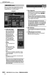
You can be used as conventional MIX buses. However in 1 the MIXER SETUP screen (SYS/W.CLOCK func- C INIT (Initialize) For each surround mode. The graphic below the buttons will be exchanged with the MIX bus that had ...; 6.1ch This mode uses seven channels: 5.1ch with the earlier-numbered buses. (Buses not used as surround buses can be used as surround buses. 244 PM5D/PM5D-RH Owner's Manual Reference section For surround mode 3-1, MIX buses 1-4 or 9-13 can be used . For surround mode 5.1, MIX buses 1-6 or 9-14 can be used...
You can be used as conventional MIX buses. However in 1 the MIXER SETUP screen (SYS/W.CLOCK func- C INIT (Initialize) For each surround mode. The graphic below the buttons will be exchanged with the MIX bus that had ...; 6.1ch This mode uses seven channels: 5.1ch with the earlier-numbered buses. (Buses not used as surround buses can be used as surround buses. 244 PM5D/PM5D-RH Owner's Manual Reference section For surround mode 3-1, MIX buses 1-4 or 9-13 can be used . For surround mode 5.1, MIX buses 1-6 or 9-14 can be used...


