

Owner's Manual
Page 2
... measures: Relocate either this product to accessories and/ or another product use this product in a residential environment will not occur in all servicing to the instructions found to products distributed by Yamaha Corporation of radio or TV interference, relocate/reorient the antenna. If ...with the apparatus. Install in the users manual, may void your use attachments/accessories specified by the manufacturer. 12 Use only with the cart, stand, tripod, bracket, or table specified by Yamaha may cause interference harmful to avoid injury from tip-over. 13...
... measures: Relocate either this product to accessories and/ or another product use this product in a residential environment will not occur in all servicing to the instructions found to products distributed by Yamaha Corporation of radio or TV interference, relocate/reorient the antenna. If ...with the apparatus. Install in the users manual, may void your use attachments/accessories specified by the manufacturer. 12 Use only with the cart, stand, tripod, bracket, or table specified by Yamaha may cause interference harmful to avoid injury from tip-over. 13...
Owner's Manual
Page 4
...down, or place it has been turned OFF. Doing so can result in excessive current flow that can damage it inspected by Yamaha). • Only use it near water or in damp or wet conditions, or place containers on the name plate of the device. • Do not ... precautions include, but are not limited to, the following : Power supply/Power cord • Use only the specified power supply (PW800W or an equivalent recommended by qualified Yamaha service personnel. WARNING Always follow the basic precautions listed below to disassemble the internal parts or modify...
...down, or place it has been turned OFF. Doing so can result in excessive current flow that can damage it inspected by Yamaha). • Only use it near water or in damp or wet conditions, or place containers on the name plate of the device. • Do not ... precautions include, but are not limited to, the following : Power supply/Power cord • Use only the specified power supply (PW800W or an equivalent recommended by qualified Yamaha service personnel. WARNING Always follow the basic precautions listed below to disassemble the internal parts or modify...
Owner's Manual
Page 5
... personnel about replacing defective components. (5)-1 2/2 When you experience any gaps or openings on it, and avoid use the headphones for damage caused by qualified Yamaha service personnel. • Do not use excessive force on the device (vents etc.). • Avoid inserting or dropping foreign objects (paper, plastic, metal, etc.) into any...
... personnel about replacing defective components. (5)-1 2/2 When you experience any gaps or openings on it, and avoid use the headphones for damage caused by qualified Yamaha service personnel. • Do not use excessive force on the device (vents etc.). • Avoid inserting or dropping foreign objects (paper, plastic, metal, etc.) into any...
Owner's Manual
Page 6
...53 Operations in the STEREO A/B channel strip 54 MATRIX section 55 Items in the MATRIX section 55 Operations in the MATRIX section 55 7 Using the Selected Channel section ...57 About the SELECTED CHANNEL section 57 Items in the SELECTED CHANNEL section 57 GROUP 57 CHANNEL SELECT 58 DELAY ...in the DCA strip 73 Using DCA Groups 74 Assigning channels to DCA groups 74 Controlling DCA groups 75 Using mute groups 75 Assigning channels to mute groups 75 Controlling mute groups 76 Using the Mute Safe function 76 Using EQ Link and Compressor Link 77 6 PM5D/PM5D-RH Owner's Manual Table ...
...53 Operations in the STEREO A/B channel strip 54 MATRIX section 55 Items in the MATRIX section 55 Operations in the MATRIX section 55 7 Using the Selected Channel section ...57 About the SELECTED CHANNEL section 57 Items in the SELECTED CHANNEL section 57 GROUP 57 CHANNEL SELECT 58 DELAY ...in the DCA strip 73 Using DCA Groups 74 Assigning channels to DCA groups 74 Controlling DCA groups 75 Using mute groups 75 Assigning channels to mute groups 75 Controlling mute groups 76 Using the Mute Safe function 76 Using EQ Link and Compressor Link 77 6 PM5D/PM5D-RH Owner's Manual Table ...
Owner's Manual
Page 7
...121 Transmitting MIDI events when you switch scenes ...122 Using GPI (General Purpose Interface 123 Using GPI IN 123 Calibrating the GPI IN ports 125 Using GPI OUT 126 17 Using memory cards 128 Using memory cards with the PM5D 128 Saving files to a memory card 128 Loading files...connections 143 Basic settings for cascade connection 143 Selecting the buses used for cascade connection 144 Connecting the PM5D to a computer via USB ..........146 Caution when using the USB TO HOST connector ........ 146 Initializing the PM5D's internal memory 147 Adjusting the faders and input/output gain ...
...121 Transmitting MIDI events when you switch scenes ...122 Using GPI (General Purpose Interface 123 Using GPI IN 123 Calibrating the GPI IN ports 125 Using GPI OUT 126 17 Using memory cards 128 Using memory cards with the PM5D 128 Saving files to a memory card 128 Loading files...connections 143 Basic settings for cascade connection 143 Selecting the buses used for cascade connection 144 Connecting the PM5D to a computer via USB ..........146 Caution when using the USB TO HOST connector ........ 146 Initializing the PM5D's internal memory 147 Adjusting the faders and input/output gain ...
Owner's Manual
Page 10
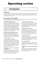
... types Separately sold as an Add-On Effect for purchasing the Yamaha PM5D digital mixing console. As input channels, it provides 24 MIX channels, eight MATRIX channels, and two STEREO channels. For MIX channels and MATRIX channels, encoders allow you can use the SELECTED CHANNEL section to manually control the principal parameters (delay...
... types Separately sold as an Add-On Effect for purchasing the Yamaha PM5D digital mixing console. As input channels, it provides 24 MIX channels, eight MATRIX channels, and two STEREO channels. For MIX channels and MATRIX channels, encoders allow you can use the SELECTED CHANNEL section to manually control the principal parameters (delay...
Owner's Manual
Page 11
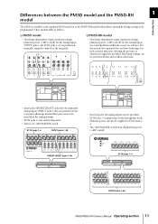
... absence of a signal are performed manually, using the controls of the top panel. ❏ PM5D-RH model • Head amp adjustments (input sensitivity settings, phantom power (+48V) on/off . Differences between the PM5D model and the PM5D-RH 1 model Introduction The PM5D is no +48V MASTER switch. These models.... • ST IN jacks 1-4 support mic levels through line levels. INSERT IN/OUT jacks 1-48 ST IN jacks 1-4 INPUT jacks 1-48 PM5D/PM5D-RH Owner's Manual Operating section 11 Head amp settings can also be supplied to ST IN jacks 1- 4. • The +48V MASTER switch ...
... absence of a signal are performed manually, using the controls of the top panel. ❏ PM5D-RH model • Head amp adjustments (input sensitivity settings, phantom power (+48V) on/off . Differences between the PM5D model and the PM5D-RH 1 model Introduction The PM5D is no +48V MASTER switch. These models.... • ST IN jacks 1-4 support mic levels through line levels. INSERT IN/OUT jacks 1-48 ST IN jacks 1-4 INPUT jacks 1-48 PM5D/PM5D-RH Owner's Manual Operating section 11 Head amp settings can also be supplied to ST IN jacks 1- 4. • The +48V MASTER switch ...
Owner's Manual
Page 12
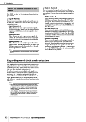
... MIX buses. These channels are not synchronized with the PM5D can also be transmitted correctly, and unpleasant noise will occur. Regarding word clock synchronization The signal used as follows. • Input channels 1-48 These channels are used mainly to MATRIX buses, and output them from the ...to MIX buses, and output them from an external device via the PM5D's digital input/output jacks or via a digital I /O card that if the word clock is sent from the internal effects. These channels are used to process stereo signals. By default, the input signals from MIX ...
... MIX buses. These channels are not synchronized with the PM5D can also be transmitted correctly, and unpleasant noise will occur. Regarding word clock synchronization The signal used as follows. • Input channels 1-48 These channels are used mainly to MATRIX buses, and output them from the ...to MIX buses, and output them from an external device via the PM5D's digital input/output jacks or via a digital I /O card that if the word clock is sent from the internal effects. These channels are used to process stereo signals. By default, the input signals from MIX ...
Owner's Manual
Page 15
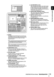
...sections This section executes the functions that will be controlled by moving the upper part of the DCA strip section (K) (➥ p.73). PM5D/PM5D-RH Owner's Manual Operating section 15 Mute operations for control from the MONITOR OUT jacks, and adjusts the lev- Top, front, and ... frame forward or backward. 8 9 N OP Q JR R K M LT S O CUE/MONITOR section This section selects the monitor source that will be used when you make system-wide settings and control mix parameters for a channel (➥ p.91). els. K DCA strip section From this section (➥ p.75...
...sections This section executes the functions that will be controlled by moving the upper part of the DCA strip section (K) (➥ p.73). PM5D/PM5D-RH Owner's Manual Operating section 15 Mute operations for control from the MONITOR OUT jacks, and adjusts the lev- Top, front, and ... frame forward or backward. 8 9 N OP Q JR R K M LT S O CUE/MONITOR section This section selects the monitor source that will be used when you make system-wide settings and control mix parameters for a channel (➥ p.91). els. K DCA strip section From this section (➥ p.75...
Owner's Manual
Page 17
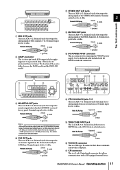
...by its [CUE] key. Female XLR plug 2 (hot) 3 (cold) 1 (ground) M DC POWER INPUT connector This is +4 dBu. Use the dedicated cable included with the PM5D to -2 dBu (maximum level +18 dBu) if necessary. J CUE OUT jacks These are XLR-3-32 (balanced) jacks that output the monitor signal...pin female XLR output jack for connecting the PW800W power supply. Nominal output level is +4 dBu. Nominal input level is +4 dBu. For details, contact your Yamaha dealer. Female XLR plug 2 (hot) 3 (cold) 1 (ground) H LAMP connector This is a D-sub 25-pin female connector that output the ...
...by its [CUE] key. Female XLR plug 2 (hot) 3 (cold) 1 (ground) M DC POWER INPUT connector This is +4 dBu. Use the dedicated cable included with the PM5D to -2 dBu (maximum level +18 dBu) if necessary. J CUE OUT jacks These are XLR-3-32 (balanced) jacks that output the monitor signal...pin female XLR output jack for connecting the PW800W power supply. Nominal output level is +4 dBu. Nominal input level is +4 dBu. For details, contact your Yamaha dealer. Female XLR plug 2 (hot) 3 (cold) 1 (ground) H LAMP connector This is a D-sub 25-pin female connector that output the ...
Owner's Manual
Page 18
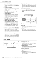
Messages received at the MIDI IN connector are used to the PM5D. a CASCADE IN connector This is a D-sub half-pitch 68-pin female connector that can be connected to this connector and used to transmit and receive MIDI messages to and from an external device to perform operations in ...this OFF. Be careful not to another manufacturer is a D-sub 9-pin male connector for remotely controlling an external head amp device (e.g., Yamaha AD8HR or AD824) that...
Messages received at the MIDI IN connector are used to the PM5D. a CASCADE IN connector This is a D-sub half-pitch 68-pin female connector that can be connected to this connector and used to transmit and receive MIDI messages to and from an external device to perform operations in ...this OFF. Be careful not to another manufacturer is a D-sub 9-pin male connector for remotely controlling an external head amp device (e.g., Yamaha AD8HR or AD824) that...
Owner's Manual
Page 19
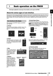
...switch between screens within the same function. ❏ Buttons Buttons in the display, and how to use them. 3 Basic operation on the PM5D This chapter explains the various types of user interface used to input characters, numerals, and symbols into the box. ❏ Tabs Tab The screen names ...shown in the display is called the "pointer." User interface in the display The user interface in the PM5D's display uses the following components. ❏ Pointer The arrow shown in the upper left and right allow you want to assign a name to a ...
...switch between screens within the same function. ❏ Buttons Buttons in the display, and how to use them. 3 Basic operation on the PM5D This chapter explains the various types of user interface used to input characters, numerals, and symbols into the box. ❏ Tabs Tab The screen names ...shown in the display is called the "pointer." User interface in the display The user interface in the PM5D's display uses the following components. ❏ Pointer The arrow shown in the upper left and right allow you want to assign a name to a ...
Owner's Manual
Page 20
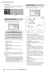
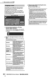
... [ENTER]" will return to the first screen in a single operation. (When you hold down the [SHIFT] key. 20 PM5D/PM5D-RH Owner's Manual Operating section B CURSOR keys These keys are used to edit settings and values in the display are gathered into a single screen, you press the key for the desired... C Input functions These keys access functions that function. 4 5 A [DEC/CANCEL]/[INC/OK] keys Use these buttons can also use the scroll bar to view the portion that affect the entire PM5D. Hint If you hold down a key in conjunction with the CURSOR keys to move the cursor rapidly,...
... [ENTER]" will return to the first screen in a single operation. (When you hold down the [SHIFT] key. 20 PM5D/PM5D-RH Owner's Manual Operating section B CURSOR keys These keys are used to edit settings and values in the display are gathered into a single screen, you press the key for the desired... C Input functions These keys access functions that function. 4 5 A [DEC/CANCEL]/[INC/OK] keys Use these buttons can also use the scroll bar to view the portion that affect the entire PM5D. Hint If you hold down a key in conjunction with the CURSOR keys to move the cursor rapidly,...
Owner's Manual
Page 21
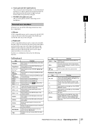
... numerals, and symbols. The numeric key pad of the SCENE MEMORY section (if the PREFERENCE 1 screen item USE NUMERIC-KEYPAD is on ), input numerical values (if off ) PM5D/PM5D-RH Owner's Manual Operating section 21 Each key (or combination of keys) has the following external user interface components.... ❏ Mouse A PS/2 compatible mouse can be connected to the MOUSE connector located on the front panel of the PM5D and used to the KEYBOARD connector located on the front panel of 3 headphones. Switch screens within the same function Accesses the function menu (...
... numerals, and symbols. The numeric key pad of the SCENE MEMORY section (if the PREFERENCE 1 screen item USE NUMERIC-KEYPAD is on ), input numerical values (if off ) PM5D/PM5D-RH Owner's Manual Operating section 21 Each key (or combination of keys) has the following external user interface components.... ❏ Mouse A PS/2 compatible mouse can be connected to the MOUSE connector located on the front panel of the PM5D and used to the KEYBOARD connector located on the front panel of 3 headphones. Switch screens within the same function Accesses the function menu (...
Owner's Manual
Page 22
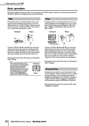
...clicking. Clicking is mainly used to turn an on-screen button on the PM5D Basic operation This section explains the basic procedures you can perform the same action using the CURSOR keys or keyboard. If you are using a PS/2 keyboard, you can perform the same action using the track pad, ... In general, you pressed the left /right is called "dragging." Click Moving the pointer to use the tapping function, you want to a specific parameter in the PM5D's display. Dragging is used to copy EQ or compressor settings to another location in the screen and then holding down the left...
...clicking. Clicking is mainly used to turn an on-screen button on the PM5D Basic operation This section explains the basic procedures you can perform the same action using the CURSOR keys or keyboard. If you are using a PS/2 keyboard, you can perform the same action using the track pad, ... In general, you pressed the left /right is called "dragging." Click Moving the pointer to use the tapping function, you want to a specific parameter in the PM5D's display. Dragging is used to copy EQ or compressor settings to another location in the screen and then holding down the left...
Owner's Manual
Page 23
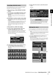
... displayed for that function will appear. Click the function name area Moving the cursor To select a parameter, use the data entry section's controllers or a PS/2 keyboard to the adjacent grid PM5D/PM5D-RH Owner's Manual Operating section 23 When you click the function name area, the function menu screen will ...move when you click on the PM5D ❏ Using the keys of the DISPLAY ACCESS section 1 From the keys of the key you can be accessed in the display using a mouse or the track pad, the cursor will move in the direction of...
... displayed for that function will appear. Click the function name area Moving the cursor To select a parameter, use the data entry section's controllers or a PS/2 keyboard to the adjacent grid PM5D/PM5D-RH Owner's Manual Operating section 23 When you click the function name area, the function menu screen will ...move when you click on the PM5D ❏ Using the keys of the DISPLAY ACCESS section 1 From the keys of the key you can be accessed in the display using a mouse or the track pad, the cursor will move in the direction of...
Owner's Manual
Page 24
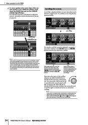
... will move the scroll bar box step-wise in the direction indicated. If you turn the encoder. 24 PM5D/PM5D-RH Owner's Manual Operating section Hint If the cursor is located on a grid such as clicking the button or button..., depending on the PM5D 2 To move quickly to the outer edge of the current window or to move the cursor toward the left... direction in which the cursor is displayed if there are holding down the [SHIFT] key and use the CURSOR keys. the screen will scroll toward the left .
... will move the scroll bar box step-wise in the direction indicated. If you turn the encoder. 24 PM5D/PM5D-RH Owner's Manual Operating section Hint If the cursor is located on a grid such as clicking the button or button..., depending on the PM5D 2 To move quickly to the outer edge of the current window or to move the cursor toward the left... direction in which the cursor is displayed if there are holding down the [SHIFT] key and use the CURSOR keys. the screen will scroll toward the left .
Owner's Manual
Page 25
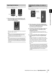
...of 1, click the right button or left button of the track pad (or mouse). Adjust the fader value Basic operation on the PM5D The button will be selected). PM5D/PM5D-RH Owner's Manual Operating section 25 Hint You can also click by one step. 3 To raise or lower the value continuously..., use the left/right buttons of a PS/2 keyboard) to click the knob/fader. Adjust the 3 knob value Click Off ➠ On 1 Move the ...
...of 1, click the right button or left button of the track pad (or mouse). Adjust the fader value Basic operation on the PM5D The button will be selected). PM5D/PM5D-RH Owner's Manual Operating section 25 Hint You can also click by one step. 3 To raise or lower the value continuously..., use the left/right buttons of a PS/2 keyboard) to click the knob/fader. Adjust the 3 knob value Click Off ➠ On 1 Move the ...
Owner's Manual
Page 26
...applies in the same way. If the cursor is connected, you can use it . Note The number of characters that point. Pressing the key of character string copied to the buffer memory. 26 PM5D/PM5D-RH Owner's Manual Operating section PASTE button Pastes the character string that ...range. 1 Use the character palette (or a PS/2 keyboard) to the right. 2 Input the subsequent characters in ...
...applies in the same way. If the cursor is connected, you can use it . Note The number of characters that point. Pressing the key of character string copied to the buffer memory. 26 PM5D/PM5D-RH Owner's Manual Operating section PASTE button Pastes the character string that ...range. 1 Use the character palette (or a PS/2 keyboard) to the right. 2 Input the subsequent characters in ...
Owner's Manual
Page 27
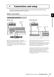
...phantom power (+48V) on /off are controlled from the top panel AD IN section (➥ p.36). However, this can be used to its default state ➥ p.32) PM5D/PM5D-RH Owner's Manual Operating section 27 INPUT jacks 1-48 and ST IN jacks 1-4 can be switched on returning the patching to ...sensitivity, pad on/off, and phantom power (+48V) on /off as a whole by the rear panel [+48V MASTER] switch. ST IN jacks 1-4 are used mainly to connect microphones or monaural line-level devices. On either model, the default state is for the first time. However, all phantom power can...
...phantom power (+48V) on /off are controlled from the top panel AD IN section (➥ p.36). However, this can be used to its default state ➥ p.32) PM5D/PM5D-RH Owner's Manual Operating section 27 INPUT jacks 1-48 and ST IN jacks 1-4 can be switched on returning the patching to ...sensitivity, pad on/off, and phantom power (+48V) on /off as a whole by the rear panel [+48V MASTER] switch. ST IN jacks 1-4 are used mainly to connect microphones or monaural line-level devices. On either model, the default state is for the first time. However, all phantom power can...


