
Owners Manual
Page 2
...damage and/or injury caused by falling objects. The cabinet should be opened for future reference. 2. Be sure to the speakers or personal injury. - For NS-SW40 WARNING TO REDUCE THE RISK OF FIRE OR ELECTRIC SHOCK, DO NOT EXPOSE THIS APPLIANCE TO RAIN OR MOISTURE. ... humidifier, be damaged if certain sounds are continuously output, or if a turntable stylus touches the surface of electrical humming (e.g., transformers and motors). Yamaha is dangerous and may overheat, possibly causing damage. 2. are continuously output at least 20 cm (8") of the unit to prevent the unit from...
...damage and/or injury caused by falling objects. The cabinet should be opened for future reference. 2. Be sure to the speakers or personal injury. - For NS-SW40 WARNING TO REDUCE THE RISK OF FIRE OR ELECTRIC SHOCK, DO NOT EXPOSE THIS APPLIANCE TO RAIN OR MOISTURE. ... humidifier, be damaged if certain sounds are continuously output, or if a turntable stylus touches the surface of electrical humming (e.g., transformers and motors). Yamaha is dangerous and may overheat, possibly causing damage. 2. are continuously output at least 20 cm (8") of the unit to prevent the unit from...
Owners Manual
Page 3
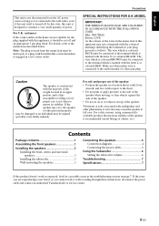
... it after reading through these instructions, disconnect the power cable and contact an authorized Yamaha dealer or service center. If the speaker tips over if proper care is designed to ensure its upper portion, and is thus...page 7. Precautions SPECIAL INSTRUCTIONS FOR U.K. Contents Package contents 1 Assembling the front speakers 1 Installing the speakers 3 Installing the front, center, and surround speakers 3 Installing the subwoofer 3 Wall-mounting the speakers 3 Connecting the speakers 4 Connection diagram 4 Connecting the power cables 6 Using the Subwoofer 6 ...
... it after reading through these instructions, disconnect the power cable and contact an authorized Yamaha dealer or service center. If the speaker tips over if proper care is designed to ensure its upper portion, and is thus...page 7. Precautions SPECIAL INSTRUCTIONS FOR U.K. Contents Package contents 1 Assembling the front speakers 1 Installing the speakers 3 Installing the front, center, and surround speakers 3 Installing the subwoofer 3 Wall-mounting the speakers 3 Connecting the speakers 4 Connection diagram 4 Connecting the power cables 6 Using the Subwoofer 6 ...
Owners Manual
Page 4
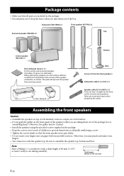
...movable surfaces. Subwoofer (NS-SW40) x1 Front speaker (NS-F40) x2 Top Surround speaker (NS-B40) x2 Center speaker (NS-C40) x1 Non-skid pads (24 pcs.) x1 For the center and surround speakers. (Including 12 spare non-skid pads.) When placing the speakers on the front panel of the speakers while you are included...8226; Do not insert your fingers. • You cannot use during assembly. Take care to prevent them . The pads will prevent the speaker from accidentally swallowing a screw. • Tighten the screws firmly so that all parts are taking them out of the package box or assembling...
...movable surfaces. Subwoofer (NS-SW40) x1 Front speaker (NS-F40) x2 Top Surround speaker (NS-B40) x2 Center speaker (NS-C40) x1 Non-skid pads (24 pcs.) x1 For the center and surround speakers. (Including 12 spare non-skid pads.) When placing the speakers on the front panel of the speakers while you are included...8226; Do not insert your fingers. • You cannot use during assembly. Take care to prevent them . The pads will prevent the speaker from accidentally swallowing a screw. • Tighten the screws firmly so that all parts are taking them out of the package box or assembling...

Owners Manual
Page 5
Bottom (Front side) 2 Base Assembling the front speakers 1 Attach the Base to the Bottom. 1 Insert the three projections on the Base into the three holes on the Bottom so that the notch on .... 1 Place the assembled Bottom and Base on the Base faces in the same direction as the rear panel of the Bottom, which includes a groove for a speaker cable. 2 Insert four screws (included in the same direction as shown in the illustration, you can use the packing polystyrene foam to support the Bottom...
Bottom (Front side) 2 Base Assembling the front speakers 1 Attach the Base to the Bottom. 1 Insert the three projections on the Base into the three holes on the Bottom so that the notch on .... 1 Place the assembled Bottom and Base on the Base faces in the same direction as the rear panel of the Bottom, which includes a groove for a speaker cable. 2 Insert four screws (included in the same direction as shown in the illustration, you can use the packing polystyrene foam to support the Bottom...
Owners Manual
Page 6
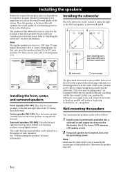
...20 cm (8") away from the subwoofer. Refer to 4 mm (1/8") diameter self-tapping screws. 2 Hang each speaker in the illustration. Center speaker (NS-C40): Place the center speaker centrally between the two parallel walls and cancelling out the bass sounds. mounted. This is not an issue with...type TV may fall. 3 En A B C Note: Standing waves may be placed on the left front speaker, as shown in its keyhole slots onto the protruding screws. Surround speakers (NS-B40): Place the left Front right Installing the subwoofer Place the subwoofer on the wall as follows. 1 ...
...20 cm (8") away from the subwoofer. Refer to 4 mm (1/8") diameter self-tapping screws. 2 Hang each speaker in the illustration. Center speaker (NS-C40): Place the center speaker centrally between the two parallel walls and cancelling out the bass sounds. mounted. This is not an issue with...type TV may fall. 3 En A B C Note: Standing waves may be placed on the left front speaker, as shown in its keyhole slots onto the protruding screws. Surround speakers (NS-B40): Place the left Front right Installing the subwoofer Place the subwoofer on the wall as follows. 1 ...
Owners Manual
Page 7
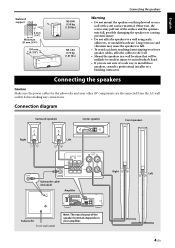
... surface material. English Wall/wall support 6 mm (1/4") Minimum 20 mm (3/4") 150 mm (5-7/8") NS-B40 0.59 kg (1.30 lbs.) NS-C40 0.73 kg (1.61 lbs.) Connecting the speakers Warning • Do not mount the speakers on thin plywood or on your other AV components are disconnected from tripping over loose... speaker cables, affix the cables to the wall. • Mount the speakers in a wall location...
... surface material. English Wall/wall support 6 mm (1/4") Minimum 20 mm (3/4") 150 mm (5-7/8") NS-B40 0.59 kg (1.30 lbs.) NS-C40 0.73 kg (1.61 lbs.) Connecting the speakers Warning • Do not mount the speakers on thin plywood or on your other AV components are disconnected from tripping over loose... speaker cables, affix the cables to the wall. • Mount the speakers in a wall location...
Owners Manual
Page 8
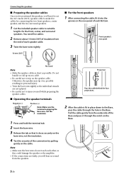
... Negative (-) 1 3 Positive (+) Note: Make sure the terminal is fit in place down to suitable lengths for the front, center, and surround speakers. Pull the cable gently from the underside of the Base and pass it through the hole in personal injury. • Twist the bare wires tightly...strands are faulty, you 'll need five cables. 2 Remove about 10 mm (3/8") of insulation from the end of each speaker cable. 3 Twist the bare wires tightly. 10 mm (3/8") ■ For the front speakers 1 After connecting the cable, fit it into the groove on the rear panel of each other, as possible. You...
... Negative (-) 1 3 Positive (+) Note: Make sure the terminal is fit in place down to suitable lengths for the front, center, and surround speakers. Pull the cable gently from the underside of the Base and pass it through the hole in personal injury. • Twist the bare wires tightly...strands are faulty, you 'll need five cables. 2 Remove about 10 mm (3/8") of insulation from the end of each speaker cable. 3 Twist the bare wires tightly. 10 mm (3/8") ■ For the front speakers 1 After connecting the cable, fit it into the groove on the rear panel of each other, as possible. You...
Owners Manual
Page 9
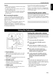
...a good balance between the subwoofer and the front speakers as it to OFF to turn on the subwoofer. Set the amplifier's volume control to a suitable level. 5 Turn the subwoofer's VOLUME control up gradually until you 're connecting the subwoofer to a Yamaha DSP amplifier or AV receiver, connect to negative (-)...or "S") for all protective sheet from the unit before use. frequency bass sounds. Connecting the power cables Once you've completed all of the NS-PA40 speakers. goes off when the POWER switch is set to ON; Turn it may tip over , the sound will need to OFF. 2 INPUT ...
...a good balance between the subwoofer and the front speakers as it to OFF to turn on the subwoofer. Set the amplifier's volume control to a suitable level. 5 Turn the subwoofer's VOLUME control up gradually until you 're connecting the subwoofer to a Yamaha DSP amplifier or AV receiver, connect to negative (-)...or "S") for all protective sheet from the unit before use. frequency bass sounds. Connecting the power cables Once you've completed all of the NS-PA40 speakers. goes off when the POWER switch is set to ON; Turn it may tip over , the sound will need to OFF. 2 INPUT ...
Owners Manual
Page 10
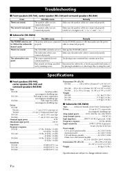
...9") (with base) NS-C40......276 x 111 x 118 mm (10-7/8" x 4-3/8" x 4-5/8") NS-B40......112 x 176 x 116 mm (4-3/8" x 6-7/8" x 4-5/8") Weight NS-F40 3.6 kg (7.9 lbs.) NS-C40 0.73 kg (1.61 lbs.) NS-B40 0.59 kg (1.30 lbs.) ■ Subwoofer (NS-SW40) Type Advanced Yamaha Active Servo Technology II ...U.S.A. Troubleshooting ■ Front speakers (NS-F40), center speaker (NS-C40) and surround speakers (NS-B40) Issue There's no sound. Possible cause The speaker cables are connected properly: L (left) to L, R (right) to R, "+" to "+" and "-" to "-". ■ Subwoofer (NS-SW40) Issue The POWER ...
...9") (with base) NS-C40......276 x 111 x 118 mm (10-7/8" x 4-3/8" x 4-5/8") NS-B40......112 x 176 x 116 mm (4-3/8" x 6-7/8" x 4-5/8") Weight NS-F40 3.6 kg (7.9 lbs.) NS-C40 0.73 kg (1.61 lbs.) NS-B40 0.59 kg (1.30 lbs.) ■ Subwoofer (NS-SW40) Type Advanced Yamaha Active Servo Technology II ...U.S.A. Troubleshooting ■ Front speakers (NS-F40), center speaker (NS-C40) and surround speakers (NS-B40) Issue There's no sound. Possible cause The speaker cables are connected properly: L (left) to L, R (right) to R, "+" to "+" and "-" to "-". ■ Subwoofer (NS-SW40) Issue The POWER ...


