

Owner's Manual
Page 3
... To prevent lightning damage, disconnect the AC power plug when there is designed to exceed the speakers' maximum input. ● As these speakers contain strong magnets (though all of power. YAMAHA shall not be damaged. ● When using an amplifier with the letter L or coloured ... the owner's responsibility. CAUTION: Read this before concluding that neither core is faulty. ● When not planning to this YAMAHA NS-P210 Speaker Package. English Thank you for your local main voltage BEFORE plugging into the AC 220V-240V main supply. 110V-120V Voltages ...
... To prevent lightning damage, disconnect the AC power plug when there is designed to exceed the speakers' maximum input. ● As these speakers contain strong magnets (though all of power. YAMAHA shall not be damaged. ● When using an amplifier with the letter L or coloured ... the owner's responsibility. CAUTION: Read this before concluding that neither core is faulty. ● When not planning to this YAMAHA NS-P210 Speaker Package. English Thank you for your local main voltage BEFORE plugging into the AC 220V-240V main supply. 110V-120V Voltages ...

Owner's Manual
Page 4
... of the amplifier. ● The AUTO STANDBY switch saves you the trouble of main/rear speakers (NX-210P), a center speaker (NX-C210) and a subwoofer system (SWP201). COMPONENTS OF THE PACKAGE The speaker package "NS-P210" is designed for use ......... 11 ADVANCED YAMAHA ACTIVE SERVO TECHNOLOGY (for SW-P201 12 TROUBLESHOOTING (for SW-P201) ......... 13 SPECIFICATIONS 14...
... of the amplifier. ● The AUTO STANDBY switch saves you the trouble of main/rear speakers (NX-210P), a center speaker (NX-C210) and a subwoofer system (SWP201). COMPONENTS OF THE PACKAGE The speaker package "NS-P210" is designed for use ......... 11 ADVANCED YAMAHA ACTIVE SERVO TECHNOLOGY (for SW-P201 12 TROUBLESHOOTING (for SW-P201) ......... 13 SPECIFICATIONS 14...
Owner's Manual
Page 5
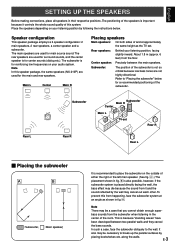
.... 6 feet) from the subwoofer when listening in their respective positions. To prevent this from it controls the whole sound quality of this speaker package, the same speakers (NX-210P) are not highly directional. It also may cancel out each other. Refer to the wall. bass sounds from the floor.... In such a case, face the subwoofer obliquely to "Placing the subwoofer" below . English SETTING UP THE SPEAKERS Before making connections, place all speakers in the center of the room. This is recommended to break up the parallel surfaces by the wall may be a case...
.... 6 feet) from the subwoofer when listening in their respective positions. To prevent this from it controls the whole sound quality of this speaker package, the same speakers (NX-210P) are not highly directional. It also may cancel out each other. Refer to the wall. bass sounds from the floor.... In such a case, face the subwoofer obliquely to "Placing the subwoofer" below . English SETTING UP THE SPEAKERS Before making connections, place all speakers in the center of the room. This is recommended to break up the parallel surfaces by the wall may be a case...
Owner's Manual
Page 6
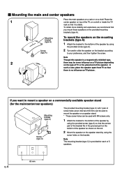
... provided screw (type A) so that the convex part of the bracket fits in the grooved part on the bottom of the speaker as shown on the left. 2 Mount the speaker on the speaker stand by using the screw holes on a shelf or inside the TV rack so that you want to mount... the provided mounting brackets (type A). To obtain more stability and usefulness, we recommend that it is provided for the main/center/rear speakers) Mounting bracket (type C) Screw (type A) The provided mounting bracket (type C) with M4 screws only. 1 Attach the bracket to your preference, and then tighten the ...
... provided screw (type A) so that the convex part of the bracket fits in the grooved part on the bottom of the speaker as shown on the left. 2 Mount the speaker on the speaker stand by using the screw holes on a shelf or inside the TV rack so that you want to mount... the provided mounting brackets (type A). To obtain more stability and usefulness, we recommend that it is provided for the main/center/rear speakers) Mounting bracket (type C) Screw (type A) The provided mounting bracket (type C) with M4 screws only. 1 Attach the bracket to your preference, and then tighten the ...
Owner's Manual
Page 7
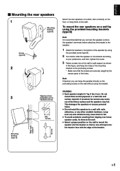
... (type B) Screw (type B) 2 3 Mounting bracket (type B) Wall/ wall support 65 mm Tapping screw (Available at the hardware store) Min. 12 mm Mount the rear speakers on a shelf, rack or directly on the floor, or hang them on the protruding screws. * Make sure that the screws are securely caught by using...cause them to the wall. ● Select a proper position on the wall without using the provided screw (type B). 2 Turn and/or slide the speaker on the bracket according to your preference, and then, tighten the screw. 3 Fasten screws into a firm wall or wall support as shown in the figure...
... (type B) Screw (type B) 2 3 Mounting bracket (type B) Wall/ wall support 65 mm Tapping screw (Available at the hardware store) Min. 12 mm Mount the rear speakers on a shelf, rack or directly on the floor, or hang them on the protruding screws. * Make sure that the screws are securely caught by using...cause them to the wall. ● Select a proper position on the wall without using the provided screw (type B). 2 Turn and/or slide the speaker on the bracket according to your preference, and then, tighten the screw. 3 Fasten screws into a firm wall or wall support as shown in the figure...
Owner's Manual
Page 8
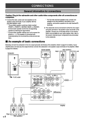
...reverse the polarity (+, -). CONNECTIONS General information for connections Caution: Plug in this section that is more suitable for your amplifier, and another speaker to the right (marked R) terminals. ● The subwoofer can be connected to the subwoofer. Ⅵ An example of basic connections ...Basically, connect the subwoofer to the line output (pin jack) terminal(s) of the amplifier. (Refer to page 8 for details.) Center speaker Rear speakers Right Left Subwoofer POWER ON OFF REAR R REAR L CENTER VOLUME STANDBY-RED ON-GREEN AUTO STANDBY HIGH LOW OFF 0 I0 INPUT2 ...
...reverse the polarity (+, -). CONNECTIONS General information for connections Caution: Plug in this section that is more suitable for your amplifier, and another speaker to the right (marked R) terminals. ● The subwoofer can be connected to the subwoofer. Ⅵ An example of basic connections ...Basically, connect the subwoofer to the line output (pin jack) terminal(s) of the amplifier. (Refer to page 8 for details.) Center speaker Rear speakers Right Left Subwoofer POWER ON OFF REAR R REAR L CENTER VOLUME STANDBY-RED ON-GREEN AUTO STANDBY HIGH LOW OFF 0 I0 INPUT2 ...
Owner's Manual
Page 9
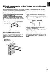
....] 10 mm Subwoofer (INPUT1/OUTPUT terminals) Connect the (+) terminals on the cord at the terminal. Note Do not let the bare speaker wires touch each other side has no line. If the connections are faulty, no line. Red: positive (+) Black: negative (-) White broken line How to Connect: 1 ... and the amplifier using one side of the cord. E-7 Do not bundle or roll up the excess part of them. English Ⅵ How to connect speaker cords to lock securely on the cord's wire end. 4 Test the firmness of the connection by pulling lightly on both components using the other side...
....] 10 mm Subwoofer (INPUT1/OUTPUT terminals) Connect the (+) terminals on the cord at the terminal. Note Do not let the bare speaker wires touch each other side has no line. If the connections are faulty, no line. Red: positive (+) Black: negative (-) White broken line How to Connect: 1 ... and the amplifier using one side of the cord. E-7 Do not bundle or roll up the excess part of them. English Ⅵ How to connect speaker cords to lock securely on the cord's wire end. 4 Test the firmness of the connection by pulling lightly on both components using the other side...
Owner's Manual
Page 10
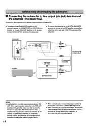
...subwoofer to the OUTPUT terminals on the rear of the DSP amplifier, connect them to the PRE OUT terminals. Instead, connect the subwoofer to the speaker output terminals of the amplifier. (Refer to pages 6 and 7.) E-8 ● When connecting to a monaural line output terminal of the amplifier, ... the subwoofer to line output (pin jack) terminals of the amplifier (The basic way) Connect the main speakers to the speaker output terminals of the amplifier. ● To connect with a YAMAHA DSP amplifier (or AV receiver), connect the SUBWOOFER (or LOW PASS etc.) terminal on the rear of ...
...subwoofer to the OUTPUT terminals on the rear of the DSP amplifier, connect them to the PRE OUT terminals. Instead, connect the subwoofer to the speaker output terminals of the amplifier. (Refer to pages 6 and 7.) E-8 ● When connecting to a monaural line output terminal of the amplifier, ... the subwoofer to line output (pin jack) terminals of the amplifier (The basic way) Connect the main speakers to the speaker output terminals of the amplifier. ● To connect with a YAMAHA DSP amplifier (or AV receiver), connect the SUBWOOFER (or LOW PASS etc.) terminal on the rear of ...
Owner's Manual
Page 11
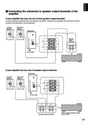
... of the subwoofer to the INPUT1 terminals of the subwoofer, and connect the OUTPUT terminals of speaker output terminals Subwoofer Left main Right main POWER ON speaker speaker OFF VOLUME STANDBY-RED ON-GREEN AUTO STANDBY HIGH LOW OFF 0 I0 INPUT2 /MONO INPUT1... FROM AMPLIFIER OUTPUT TO SPEAKERS INPUT1 FROM AMPLIFIER OUTPUT TO SPEAKERS To AC outlet A B Amplifier Speaker output terminals (Both A and B speaker outputs must be ON.) E-9 Left main speaker Right main speaker Subwoofer POWER ON OFF VOLUME STANDBY-RED ON-GREEN AUTO STANDBY...
... of the subwoofer to the INPUT1 terminals of the subwoofer, and connect the OUTPUT terminals of speaker output terminals Subwoofer Left main Right main POWER ON speaker speaker OFF VOLUME STANDBY-RED ON-GREEN AUTO STANDBY HIGH LOW OFF 0 I0 INPUT2 /MONO INPUT1... FROM AMPLIFIER OUTPUT TO SPEAKERS INPUT1 FROM AMPLIFIER OUTPUT TO SPEAKERS To AC outlet A B Amplifier Speaker output terminals (Both A and B speaker outputs must be ON.) E-9 Left main speaker Right main speaker Subwoofer POWER ON OFF VOLUME STANDBY-RED ON-GREEN AUTO STANDBY...
Owner's Manual
Page 12
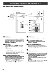
... POWER ON OFF 220V-240V 110V-120V VOLUME STANDBY-RED ON-GREEN AUTO STANDBY HIGH LOW OFF 0 I0 INPUT2 /MONO INPUT1 FROM AMPLIFIER OUTPUT TO SPEAKERS VOLTAGE SELECTOR 220V-240V 110V-120V 8 VOLUME 2 3 4 STANDBY-RED ON-GREEN AUTO STANDBY HIGH LOW OFF 0 I0 INPUT2 /MONO 7 5 INPUT1 FROM AMPLIFIER... only when the POWER switch (1) is in the OFF position. 4 INPUT2 terminals Used to input line level signals from the amplifier to the main speakers by way of these terminals. 7 VOLUME control Adjusts the volume level. 8 VOLTAGE SELECTOR switch (General model only) If the preset setting of the...
... POWER ON OFF 220V-240V 110V-120V VOLUME STANDBY-RED ON-GREEN AUTO STANDBY HIGH LOW OFF 0 I0 INPUT2 /MONO INPUT1 FROM AMPLIFIER OUTPUT TO SPEAKERS VOLTAGE SELECTOR 220V-240V 110V-120V 8 VOLUME 2 3 4 STANDBY-RED ON-GREEN AUTO STANDBY HIGH LOW OFF 0 I0 INPUT2 /MONO 7 5 INPUT1 FROM AMPLIFIER... only when the POWER switch (1) is in the OFF position. 4 INPUT2 terminals Used to input line level signals from the amplifier to the main speakers by way of these terminals. 7 VOLUME control Adjusts the volume level. 8 VOLTAGE SELECTOR switch (General model only) If the preset setting of the...
Owner's Manual
Page 13
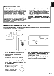
... will turn on automatically by following the procedures described below. VOLUME 0 I0 Once the volume balance between the subwoofer and the main speakers is recommended to set the AUTO STANDBY switch to the subwoofer. If that occurs, set the VOLUME control to the middle position when...'s volume control to the desired listening level. 4 Increase the volume gradually to adjust the volume balance between the subwoofer and the main speakers by sensing audio signals input to the OFF or LOW position. * The level of low frequency input signal. Set this adjustment again....
... will turn on automatically by following the procedures described below. VOLUME 0 I0 Once the volume balance between the subwoofer and the main speakers is recommended to set the AUTO STANDBY switch to the subwoofer. If that occurs, set the VOLUME control to the middle position when...'s volume control to the desired listening level. 4 Increase the volume gradually to adjust the volume balance between the subwoofer and the main speakers by sensing audio signals input to the OFF or LOW position. * The level of low frequency input signal. Set this adjustment again....
Owner's Manual
Page 14
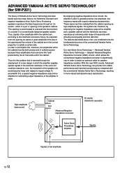
...must overcome the "load" presented by employing the negative-impedance output drive amplifier and a speaker cabinet with the Helmholtz resonator, reproduce an extremely wide range of Yamaha Active Servo Technology has been based upon two major factors, the Helmholtz resonator and negative... to zero, the movement of low amplitude within the cabinet. Advanced Yamaha Active Servo Technology - Active Servo Processing speakers reproduce the bass frequencies through the employment of the conventional Yamaha Active Servo Technology. If the electrical resistance of the voice coil could...
...must overcome the "load" presented by employing the negative-impedance output drive amplifier and a speaker cabinet with the Helmholtz resonator, reproduce an extremely wide range of Yamaha Active Servo Technology has been based upon two major factors, the Helmholtz resonator and negative... to zero, the movement of low amplitude within the cabinet. Advanced Yamaha Active Servo Technology - Active Servo Processing speakers reproduce the bass frequencies through the employment of the conventional Yamaha Active Servo Technology. If the electrical resistance of the voice coil could...
Owner's Manual
Page 15
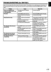
...of input signal is played. Connect them correctly, that is an influence of noise generated from such appliances and/or reposition the connected speaker cables. Move the subwoofer farther away from external appliances etc. The subwoofer turns into the standby mode unexpectedly. What to the "...below do not help, disconnect the power cord and contact your authorized YAMAHA dealer or service center. Connect them securely. Problem Power is not supplied even though the POWER switch is not securely connected. Speaker cords are not connected correctly. Set the POWER switch to the ...
...of input signal is played. Connect them correctly, that is an influence of noise generated from such appliances and/or reposition the connected speaker cables. Move the subwoofer farther away from external appliances etc. The subwoofer turns into the standby mode unexpectedly. What to the "...below do not help, disconnect the power cord and contact your authorized YAMAHA dealer or service center. Connect them securely. Problem Power is not supplied even though the POWER switch is not securely connected. Speaker cords are not connected correctly. Set the POWER switch to the ...
Owner's Manual
Page 16
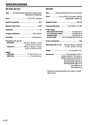
SPECIFICATIONS NX-210P, NX-C210 Type ......... Full-range acoustic-suspension speaker system Magnetically shielded type Driver 8 cm (3-1/8") cone type Nominal Input Power 30W Maximum Input Power 100W Impedance 6Ω Frequency Response 65 Hz-20 kHz Sensitivity 86 dB/2.83V/m Dimensions (W x H x D)
SPECIFICATIONS NX-210P, NX-C210 Type ......... Full-range acoustic-suspension speaker system Magnetically shielded type Driver 8 cm (3-1/8") cone type Nominal Input Power 30W Maximum Input Power 100W Impedance 6Ω Frequency Response 65 Hz-20 kHz Sensitivity 86 dB/2.83V/m Dimensions (W x H x D)


