

Owner's Manual
Page 3
... YAMAHA NS-P210 Speaker Package. Extremely loud playing of a movie soundtrack's low frequency, bass-heavy sounds or similarly loud popular music passages can result in a cool, dry, clean place - away from this appliance, it in a safe place for your plug, proceed as a plug with a rated output power higher than the nominal input power of the speakers, care should be taken never to the ON position and the AUTO STANDBY switch...
... YAMAHA NS-P210 Speaker Package. Extremely loud playing of a movie soundtrack's low frequency, bass-heavy sounds or similarly loud popular music passages can result in a cool, dry, clean place - away from this appliance, it in a safe place for your plug, proceed as a plug with a rated output power higher than the nominal input power of the speakers, care should be taken never to the ON position and the AUTO STANDBY switch...

Owner's Manual
Page 4
... your existing audio system by connecting to either the speaker terminals or the line output (pin jack) terminals of the amplifier. ● The AUTO STANDBY switch saves you the trouble of setting the POWER switch to speaker output terminals of main/rear speakers (NX-210P), a center speaker (NX-C210) and a subwoofer system (SWP201). COMPONENTS OF THE PACKAGE The speaker package "NS-P210" is designed for use ......... 11 ADVANCED YAMAHA ACTIVE SERVO TECHNOLOGY (for SW-P201 12 TROUBLESHOOTING (for...
... your existing audio system by connecting to either the speaker terminals or the line output (pin jack) terminals of the amplifier. ● The AUTO STANDBY switch saves you the trouble of setting the POWER switch to speaker output terminals of main/rear speakers (NX-210P), a center speaker (NX-C210) and a subwoofer system (SWP201). COMPONENTS OF THE PACKAGE The speaker package "NS-P210" is designed for use ......... 11 ADVANCED YAMAHA ACTIVE SERVO TECHNOLOGY (for SW-P201 12 TROUBLESHOOTING (for...
Owner's Manual
Page 5
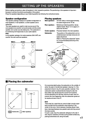
... used for reinforcing low frequencies on your listening position, facing slightly inward. English SETTING UP THE SPEAKERS Before making connections, place all speakers in fig. Å. In such a case, face the subwoofer obliquely to break up the parallel surfaces by the wall may be a case that you cannot obtain enough super- The positioning of the speakers is for surround sounds, and the center speaker...
... used for reinforcing low frequencies on your listening position, facing slightly inward. English SETTING UP THE SPEAKERS Before making connections, place all speakers in fig. Å. In such a case, face the subwoofer obliquely to break up the parallel surfaces by the wall may be a case that you cannot obtain enough super- The positioning of the speakers is for surround sounds, and the center speaker...
Owner's Manual
Page 6
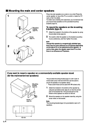
... The mounting bracket (type C) is stable. In such a case, place the speaker apart from TV so that there is no influence on a shelf or inside the TV rack so that it is provided for the main/center/rear speakers) Mounting bracket (type C) Screw (type A) The provided mounting bracket (type C) with 1 pair of screw holes (at an interval of 60 mm) can be used to mount the speaker on a speaker stand. * Those...
... The mounting bracket (type C) is stable. In such a case, place the speaker apart from TV so that there is no influence on a shelf or inside the TV rack so that it is provided for the main/center/rear speakers) Mounting bracket (type C) Screw (type A) The provided mounting bracket (type C) with 1 pair of screw holes (at an interval of 60 mm) can be used to mount the speaker on a speaker stand. * Those...
Owner's Manual
Page 7
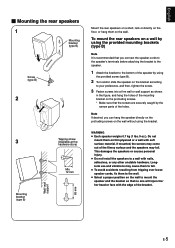
... (type B) 2 3 Mounting bracket (type B) Wall/ wall support 65 mm Tapping screw (Available at the hardware store) Min. 12 mm Mount the rear speakers on a shelf, rack or directly on the floor, or hang them on the protruding screws. * Make sure that the screws are securely caught by the narrow parts of the holes. This damages the speakers or causes personal injury. ● Do not install...
... (type B) 2 3 Mounting bracket (type B) Wall/ wall support 65 mm Tapping screw (Available at the hardware store) Min. 12 mm Mount the rear speakers on a shelf, rack or directly on the floor, or hang them on the protruding screws. * Make sure that the screws are securely caught by the narrow parts of the holes. This damages the speakers or causes personal injury. ● Do not install...
Owner's Manual
Page 8
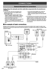
....) Center speaker Rear speakers Right Left Subwoofer POWER ON OFF REAR R REAR L CENTER VOLUME STANDBY-RED ON-GREEN AUTO STANDBY HIGH LOW OFF 0 I0 INPUT2 /MONO INPUT1 FROM AMPLIFIER OUTPUT TO SPEAKERS INPUT2 /MONO FRONT R FRONT L To AC outlet OUTPUT MAIN CENTER REAR (SURROUND) CENTER REAR (SURROUND) CENTER REAR R FRONT R A B SUB WOOFER MAIN FRONT L SPEAKERS A CAUTION SEE INSTRUCTION MANUAL FOR CORRECT SETTING. Also, refer to the owner's manual of your component to be connected to reverse the polarity (+, -). Connect each speaker cord to the corresponding speaker...
....) Center speaker Rear speakers Right Left Subwoofer POWER ON OFF REAR R REAR L CENTER VOLUME STANDBY-RED ON-GREEN AUTO STANDBY HIGH LOW OFF 0 I0 INPUT2 /MONO INPUT1 FROM AMPLIFIER OUTPUT TO SPEAKERS INPUT2 /MONO FRONT R FRONT L To AC outlet OUTPUT MAIN CENTER REAR (SURROUND) CENTER REAR (SURROUND) CENTER REAR R FRONT R A B SUB WOOFER MAIN FRONT L SPEAKERS A CAUTION SEE INSTRUCTION MANUAL FOR CORRECT SETTING. Also, refer to the owner's manual of your component to be connected to reverse the polarity (+, -). Connect each speaker cord to the corresponding speaker...
Owner's Manual
Page 9
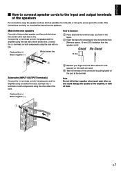
... line. English Ⅵ How to connect speaker cords to the input and output terminals of the speakers For connections, keep the speaker cords as short as shown in the figure. 2 Insert the bare wire end properly into the terminal hole. [Remove approx. 10 mm (3/8") insulation from the speaker cord.] 10 mm Subwoofer (INPUT1/OUTPUT terminals) Connect the (+) terminals on both the subwoofer and the amplifier using one side of the cord...
... line. English Ⅵ How to connect speaker cords to the input and output terminals of the speakers For connections, keep the speaker cords as short as shown in the figure. 2 Insert the bare wire end properly into the terminal hole. [Remove approx. 10 mm (3/8") insulation from the speaker cord.] 10 mm Subwoofer (INPUT1/OUTPUT terminals) Connect the (+) terminals on both the subwoofer and the amplifier using one side of the cord...
Owner's Manual
Page 10
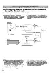
Subwoofer POWER ON OFF VOLUME STANDBY-RED ON-GREEN AUTO STANDBY HIGH LOW OFF 0 I0 INPUT2 /MONO INPUT1 FROM AMPLIFIER OUTPUT TO SPEAKERS INPUT2 To AC outlet Amplifier /MONO SUBWOOFER (LOW PASS) Pin plug cords (not included) Pin plug cord (included) SPLIT SUBWOOFER Notes ● Some amplifiers have line output terminals labeled PRE OUT. If connected, they will not produce sound. Various ways of connecting the subwoofer Ⅵ Connecting the subwoofer to line output (pin jack) terminals of the amplifier (The basic...
Subwoofer POWER ON OFF VOLUME STANDBY-RED ON-GREEN AUTO STANDBY HIGH LOW OFF 0 I0 INPUT2 /MONO INPUT1 FROM AMPLIFIER OUTPUT TO SPEAKERS INPUT2 To AC outlet Amplifier /MONO SUBWOOFER (LOW PASS) Pin plug cords (not included) Pin plug cord (included) SPLIT SUBWOOFER Notes ● Some amplifiers have line output terminals labeled PRE OUT. If connected, they will not produce sound. Various ways of connecting the subwoofer Ⅵ Connecting the subwoofer to line output (pin jack) terminals of the amplifier (The basic...
Owner's Manual
Page 11
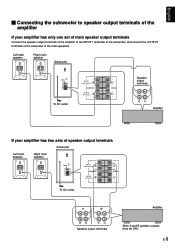
... FROM AMPLIFIER OUTPUT TO SPEAKERS INPUT1 FROM AMPLIFIER OUTPUT TO SPEAKERS Speaker output terminals To AC outlet Amplifier If your amplifier has only one set of main speaker output terminals Connect the speaker output terminals of the amplifier to the INPUT1 terminals of the subwoofer, and connect the OUTPUT terminals of the subwoofer to speaker output terminals of the amplifier If your amplifier has two sets of speaker output terminals Subwoofer Left main Right main POWER ON speaker speaker OFF VOLUME STANDBY-RED ON-GREEN AUTO STANDBY...
... FROM AMPLIFIER OUTPUT TO SPEAKERS INPUT1 FROM AMPLIFIER OUTPUT TO SPEAKERS Speaker output terminals To AC outlet Amplifier If your amplifier has only one set of main speaker output terminals Connect the speaker output terminals of the amplifier to the INPUT1 terminals of the subwoofer, and connect the OUTPUT terminals of the subwoofer to speaker output terminals of the amplifier If your amplifier has two sets of speaker output terminals Subwoofer Left main Right main POWER ON speaker speaker OFF VOLUME STANDBY-RED ON-GREEN AUTO STANDBY...
Owner's Manual
Page 12
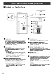
..., the subwoofer's automatic power-switching function operates as described on , the power indicator below the POWER switch lights up RED when no signal is set to the OFF position. * Make sure to change the setting of this switch only when the POWER switch (1) is in the OFF position. 4 INPUT2 terminals Used to input line level signals from the amplifier to the main speakers by way of these terminals. 7 VOLUME control Adjusts the volume level. 8 VOLTAGE SELECTOR switch (General model only...
..., the subwoofer's automatic power-switching function operates as described on , the power indicator below the POWER switch lights up RED when no signal is set to the OFF position. * Make sure to change the setting of this switch only when the POWER switch (1) is in the OFF position. 4 INPUT2 terminals Used to input line level signals from the amplifier to the main speakers by way of these terminals. 7 VOLUME control Adjusts the volume level. 8 VOLTAGE SELECTOR switch (General model only...
Owner's Manual
Page 13
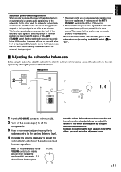
... home theater system. Rear panel POWER ON 2 OFF POWER ON OFF VOLUME STANDBY-RED ON-GREEN AUTO STANDBY HIGH LOW OFF 0 I0 INPUT2 /MONO INPUT1 FROM AMPLIFIER OUTPUT TO SPEAKERS VOLUME STANDBY-RED ON-GREEN AUTO STANDBY HIGH LOW OFF 0 I0 1, 4 1 Set the VOLUME control to minimum (0). 2 Turn on (by setting the POWER switch (1) to "ON"). Ⅵ Adjusting the subwoofer before use Before using the subwoofer, adjust the subwoofer to obtain the optimum volume balance between the subwoofer and the main speakers by sensing audio signals input to...
... home theater system. Rear panel POWER ON 2 OFF POWER ON OFF VOLUME STANDBY-RED ON-GREEN AUTO STANDBY HIGH LOW OFF 0 I0 INPUT2 /MONO INPUT1 FROM AMPLIFIER OUTPUT TO SPEAKERS VOLUME STANDBY-RED ON-GREEN AUTO STANDBY HIGH LOW OFF 0 I0 1, 4 1 Set the VOLUME control to minimum (0). 2 Turn on (by setting the POWER switch (1) to "ON"). Ⅵ Adjusting the subwoofer before use Before using the subwoofer, adjust the subwoofer to obtain the optimum volume balance between the subwoofer and the main speakers by sensing audio signals input to...
Owner's Manual
Page 14
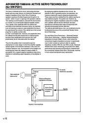
... be outputted from the cabinet opening and the volume of a new design in the correct proportion to the Helmholtz resonance theory, be the fundamental structure of Yamaha Active Servo Technology has been based upon two major factors, the Helmholtz resonator and negative-impedance drive. The system can , according to satisfy a certain ratio. Active Servo Processing speakers reproduce the bass frequencies through...
... be outputted from the cabinet opening and the volume of a new design in the correct proportion to the Helmholtz resonance theory, be the fundamental structure of Yamaha Active Servo Technology has been based upon two major factors, the Helmholtz resonator and negative-impedance drive. The system can , according to satisfy a certain ratio. Active Servo Processing speakers reproduce the bass frequencies through...
Owner's Manual
Page 15
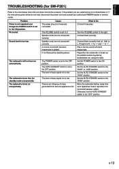
... not listed below or if the instructions given below when this unit does not function properly. Set the AUTO STANDBY switch to the ON position. Set the AUTO STANDBY switch to Do Connect it securely. E-13 Cause The power plug is set to "-". A source sound with bass frequencies. It is played. The VOLUME control is too low. The level of noise generated from such appliances and/or reposition the connected speaker cables. The level of input...
... not listed below or if the instructions given below when this unit does not function properly. Set the AUTO STANDBY switch to the ON position. Set the AUTO STANDBY switch to Do Connect it securely. E-13 Cause The power plug is set to "-". A source sound with bass frequencies. It is played. The VOLUME control is too low. The level of noise generated from such appliances and/or reposition the connected speaker cables. The level of input...
Owner's Manual
Page 16
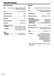
SPECIFICATIONS NX-210P, NX-C210 Type ......... Full-range acoustic-suspension speaker system Magnetically shielded type Driver 8 cm (3-1/8") cone type Nominal Input Power 30W Maximum Input Power 100W Impedance 6Ω Frequency Response 65 Hz-20 kHz Sensitivity 86 dB/2.83V/m Dimensions (W x H x D)
SPECIFICATIONS NX-210P, NX-C210 Type ......... Full-range acoustic-suspension speaker system Magnetically shielded type Driver 8 cm (3-1/8") cone type Nominal Input Power 30W Maximum Input Power 100W Impedance 6Ω Frequency Response 65 Hz-20 kHz Sensitivity 86 dB/2.83V/m Dimensions (W x H x D)


