

Owner's Manual
Page 1
... Bedienungsanleitung Manual de uso 1 A B 20dB -16 -60 GAIN PEAK SIGNAL 2 A B 20dB -16 -60 GAIN PEAK SIGNAL 3 A B 20dB -16 -60 GAIN PEAK SIGNAL 4 A B 20dB -16 -60 GAIN PEAK SIGNAL 5 A B 20dB -16 -60 GAIN PEAK SIGNAL 6 A B 20dB -16 -60 GAIN PEAK SIGNAL 7 A B 20dB -16 -60 GAIN PEAK SIGNAL 8 A B 20dB -16 -60 GAIN PEAK SIGNAL 9 A B 20dB -16 -60 GAIN PEAK SIGNAL 10...
... Bedienungsanleitung Manual de uso 1 A B 20dB -16 -60 GAIN PEAK SIGNAL 2 A B 20dB -16 -60 GAIN PEAK SIGNAL 3 A B 20dB -16 -60 GAIN PEAK SIGNAL 4 A B 20dB -16 -60 GAIN PEAK SIGNAL 5 A B 20dB -16 -60 GAIN PEAK SIGNAL 6 A B 20dB -16 -60 GAIN PEAK SIGNAL 7 A B 20dB -16 -60 GAIN PEAK SIGNAL 8 A B 20dB -16 -60 GAIN PEAK SIGNAL 9 A B 20dB -16 -60 GAIN PEAK SIGNAL 10...
Owner's Manual
Page 3
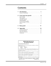
...be connected to the terminal which is marked with the letter N or coloured BLACK. Contents i Contents 1 Introduction 1 Features of the MX400 1 2 Front and rear panels 2 Input modules 2 Stereo module 5 AUX SEND module 7 GROUP module 7 ST2/MONITOR module 8 Master...ST1-R 9 Meters 10 3 Rear panel 11 4 Appendix 14 General specifications 14 Input Specifications 15 Output Specifications 16 Dimensions 16 IMPORTANT NOTICE FOR THE UNITED KINGDOM Connecting the Plug and Cord IMPORTANT: The wires in this mains lead are... pin plug. * This applies only to products distributed by YAMAHA -
...be connected to the terminal which is marked with the letter N or coloured BLACK. Contents i Contents 1 Introduction 1 Features of the MX400 1 2 Front and rear panels 2 Input modules 2 Stereo module 5 AUX SEND module 7 GROUP module 7 ST2/MONITOR module 8 Master...ST1-R 9 Meters 10 3 Rear panel 11 4 Appendix 14 General specifications 14 Input Specifications 15 Output Specifications 16 Dimensions 16 IMPORTANT NOTICE FOR THE UNITED KINGDOM Connecting the Plug and Cord IMPORTANT: The wires in this mains lead are... pin plug. * This applies only to products distributed by YAMAHA -
Owner's Manual
Page 5
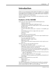
... to be switched in a wide range of applications, including PA and installed systems. The MX400 series includes three models; 8 channel, 12 channel, 16 channel, and 24 channel mixers. The level meters with variable mid-range frequency) / EQ...switch / continuously variable gain control • 3 band EQ (with peak indicators allow accurate monitoring. Features of the MX400 Each of the mono input channels provides the following two ways; 1) One of the signals from an external source ...jacks have level controls, for convenience when you for purchasing the Yamaha MX400. MX400 User's Guide
... to be switched in a wide range of applications, including PA and installed systems. The MX400 series includes three models; 8 channel, 12 channel, 16 channel, and 24 channel mixers. The level meters with variable mid-range frequency) / EQ...switch / continuously variable gain control • 3 band EQ (with peak indicators allow accurate monitoring. Features of the MX400 Each of the mono input channels provides the following two ways; 1) One of the signals from an external source ...jacks have level controls, for convenience when you for purchasing the Yamaha MX400. MX400 User's Guide
Owner's Manual
Page 6
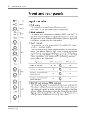
... When the post EQ signal level (nominal level 0dB) reaches -10dB, the SIGNAL indicator will light. 2 Front and rear panels Front and rear panels A 1 B 20dB 2 3 -16 -60 GAIN PEAK SIGNAL 4 80 5 -15 +15 HIGH 250 5K MID FREQ -15 +15 MID 6 -15 +15 LOW EQ 0 10 AUX 1 P R E 0 10 AUX 2 7 0 10 AUX.... For the procedure, see the explanation for the GAIN control. The GAIN control is pressed in conjunction with the SIGNAL indicator and the PEAK indicator. MX400 User's Guide Gain is variable to an appropriate level.
... When the post EQ signal level (nominal level 0dB) reaches -10dB, the SIGNAL indicator will light. 2 Front and rear panels Front and rear panels A 1 B 20dB 2 3 -16 -60 GAIN PEAK SIGNAL 4 80 5 -15 +15 HIGH 250 5K MID FREQ -15 +15 MID 6 -15 +15 LOW EQ 0 10 AUX 1 P R E 0 10 AUX 2 7 0 10 AUX.... For the procedure, see the explanation for the GAIN control. The GAIN control is pressed in conjunction with the SIGNAL indicator and the PEAK indicator. MX400 User's Guide Gain is variable to an appropriate level.
Owner's Manual
Page 19
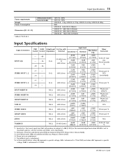
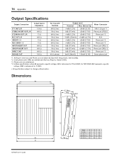
...TRS) *3 Phone jack (TRS) *3 RCA Phone jack *4 Phone jack *4 RCA XLR-3-31 type *5 *1. The talkback jack is set to 1V RMS. MX400 User's Guide Input Specifications 15 Power requirements Weight Power Consumption Dimensions (W × H × D) * 0dB=0.775V R.M.S US&Canada model General model 120V... AC, 60Hz 230V AC, 50Hz MX400-8 17kg, MX400-12 19kg, MX400-16 22kg, MX400-24 28kg 80W MX400-8 562×180.2×596mm MX400-12 682×180.2×596mm MX400-16 802×180.2×596mm MX400-24 1042×180.2×596mm Input Specifications Input...
...TRS) *3 Phone jack (TRS) *3 RCA Phone jack *4 Phone jack *4 RCA XLR-3-31 type *5 *1. The talkback jack is set to 1V RMS. MX400 User's Guide Input Specifications 15 Power requirements Weight Power Consumption Dimensions (W × H × D) * 0dB=0.775V R.M.S US&Canada model General model 120V... AC, 60Hz 230V AC, 50Hz MX400-8 17kg, MX400-12 19kg, MX400-16 22kg, MX400-24 28kg 80W MX400-8 562×180.2×596mm MX400-12 682×180.2×596mm MX400-16 802×180.2×596mm MX400-24 1042×180.2×596mm Input Specifications Input...
Owner's Manual
Page 20
...Tip=out, Ring=in, Sleeve=GND). *3. Dimensions Wl H: 180.2 155.5 13.3 31.9 434.5 D: 596 Wi W MX400 User's Guide 108.9 129.5 Model WI MX400-8 465 MX400-12 585 MX400-16 705 MX400-24 945 Wi 527 647 767 1007 W 562 682 802 1042 XLR-type connectors and Phone jacks are balanced (Tip...=HOT, Ring=COLD, Sleeve=GND). *2. 16 Appendix Output Specifications Output Connection ST1 OUT L/R STEREO INSERT...
...Tip=out, Ring=in, Sleeve=GND). *3. Dimensions Wl H: 180.2 155.5 13.3 31.9 434.5 D: 596 Wi W MX400 User's Guide 108.9 129.5 Model WI MX400-8 465 MX400-12 585 MX400-16 705 MX400-24 945 Wi 527 647 767 1007 W 562 682 802 1042 XLR-type connectors and Phone jacks are balanced (Tip...=HOT, Ring=COLD, Sleeve=GND). *2. 16 Appendix Output Specifications Output Connection ST1 OUT L/R STEREO INSERT...
Owner's Manual
Page 75
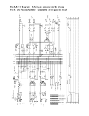
INPUT B *1*: 8 12 16 24 PHANTOM OFF (INPUT A) (PHANTOM) ON PHANTOM (+48V) INPUT INSERT I /O R 0dB REC OUT L REC OUT -10dBV R LA ON (METER) LA ON LA GROUP OUT +4dB 1-4 L ... (+V) PFL TB LEVEL GROUP 1 GROUP 2 GROUP 3 ST2/MONITOR L GROUP 4 ST2/MONITOR R STEREO 1 L STEREO 2 R (dB) +10 CH IN Pad On [+4] 0 -10 CH IN [-16] -20 -30 -40 -50 CH IN [-16] -60 GROUP SUB IN ST SUB IN [+4] TAPE IN [-10dBV] [-3] AUX [-6] 1 2 3 GROUP 4 L R STEREO 1 2 3 AUX 4 5 L R PFL PFL CTRL AFL AFL CTRL GROUP INSERT...
INPUT B *1*: 8 12 16 24 PHANTOM OFF (INPUT A) (PHANTOM) ON PHANTOM (+48V) INPUT INSERT I /O R 0dB REC OUT L REC OUT -10dBV R LA ON (METER) LA ON LA GROUP OUT +4dB 1-4 L ... (+V) PFL TB LEVEL GROUP 1 GROUP 2 GROUP 3 ST2/MONITOR L GROUP 4 ST2/MONITOR R STEREO 1 L STEREO 2 R (dB) +10 CH IN Pad On [+4] 0 -10 CH IN [-16] -20 -30 -40 -50 CH IN [-16] -60 GROUP SUB IN ST SUB IN [+4] TAPE IN [-10dBV] [-3] AUX [-6] 1 2 3 GROUP 4 L R STEREO 1 2 3 AUX 4 5 L R PFL PFL CTRL AFL AFL CTRL GROUP INSERT...

