

Owner's Manual
Page 1
...-6R 7L-8R LEVEL LEVEL MIC 0 10 0 10 +12 MULTITRACK CASSETTE RECORDER +12 +6 +3 0 -5 -10 REC 1 2 3 4 L R +12 10 10 CUE TAPE SPEED CONTROL PITCH 4.8/ 9.5 - + ON OFF SYNC ZERO STOP ON OFF REC SELECT 1 2 3 4 OFF OFF OFF OFF L R L R +6 POWER +3 0 -5 -10 METER SELECT 4TR STEREO 0 10 MIC/LINE to L TAPE TAPE MIC/ LINE INPUT-FLIP 0 10 MIC/LINE to R TAPE TAPE MIC/ LINE INPUT-FLIP 0 10 MIC/LINE to L TAPE TAPE MIC/ LINE INPUT-FLIP 0 10 MIC/LINE to R TAPE TAPE MIC/ LINE INPUT-FLIP LEVEL PAN PAN...
...-6R 7L-8R LEVEL LEVEL MIC 0 10 0 10 +12 MULTITRACK CASSETTE RECORDER +12 +6 +3 0 -5 -10 REC 1 2 3 4 L R +12 10 10 CUE TAPE SPEED CONTROL PITCH 4.8/ 9.5 - + ON OFF SYNC ZERO STOP ON OFF REC SELECT 1 2 3 4 OFF OFF OFF OFF L R L R +6 POWER +3 0 -5 -10 METER SELECT 4TR STEREO 0 10 MIC/LINE to L TAPE TAPE MIC/ LINE INPUT-FLIP 0 10 MIC/LINE to R TAPE TAPE MIC/ LINE INPUT-FLIP 0 10 MIC/LINE to L TAPE TAPE MIC/ LINE INPUT-FLIP 0 10 MIC/LINE to R TAPE TAPE MIC/ LINE INPUT-FLIP LEVEL PAN PAN...
Owner's Manual
Page 4
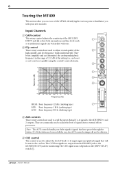
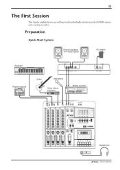
... inputs and one stereo output): a Recorder section that records and plays sound (with ease, including microphone and line-level signals such as a normal cassette recorder, doubling the recording time relative to -noise ratio in excess of 80 dB. • Punch in the range between -10% and +10%. -Owner's Manual A speed of 4.8 cm/second is switchable between the MT400 and a MIDI sequencer. You can monitor track signals adjusted by the CUE controls, while making a recording...
... inputs and one stereo output): a Recorder section that records and plays sound (with ease, including microphone and line-level signals such as a normal cassette recorder, doubling the recording time relative to -noise ratio in excess of 80 dB. • Punch in the range between -10% and +10%. -Owner's Manual A speed of 4.8 cm/second is switchable between the MT400 and a MIDI sequencer. You can monitor track signals adjusted by the CUE controls, while making a recording...
Owner's Manual
Page 7
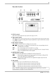
...-fader signals (signals that both microphone and line-level (such as a synthesizer) signals can be handled with your new recorder. D CUE control This control is used to external effects processors. A flat setting (i.e., no boost or cut (attenuate) the corresponding basic frequency in the range of the high, middle, and low frequency bands independently. B EQ control These rotary controls are used to adjust the level of Track (1-4) input signal and playback signal...
...-fader signals (signals that both microphone and line-level (such as a synthesizer) signals can be handled with your new recorder. D CUE control This control is used to external effects processors. A flat setting (i.e., no boost or cut (attenuate) the corresponding basic frequency in the range of the high, middle, and low frequency bands independently. B EQ control These rotary controls are used to adjust the level of Track (1-4) input signal and playback signal...
Owner's Manual
Page 10
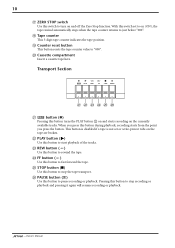
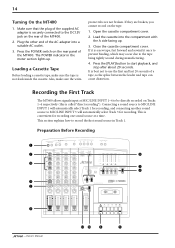
... cassette tape recorder. Set the switch to select 4.8 cm/second or 9.5 cm/second for playback of ±10%. N REC SELECT switches These switches are used to turn on and off only for recording. STEREO....The level meters display the Stereo bus signal levels (signal output from the STEREO OUT jacks). SYNC .........The dbx noise reduction system is turned on the level meters a. 4TR The level meters display the track input signal levels during recording and the track output signal levels during playback. See page 41 for recording and receive L channel (Tracks...
... cassette tape recorder. Set the switch to select 4.8 cm/second or 9.5 cm/second for playback of ±10%. N REC SELECT switches These switches are used to turn on and off only for recording. STEREO....The level meters display the Stereo bus signal levels (signal output from the STEREO OUT jacks). SYNC .........The dbx noise reduction system is turned on the level meters a. 4TR The level meters display the track input signal levels during recording and the track output signal levels during playback. See page 41 for recording and receive L channel (Tracks...
Owner's Manual
Page 11
... a tape is not set to on the currently available tracks. When you press this button to start playback of the tracks. V PLAY button (®) Use this button during playback, recording starts from the point you press the button. W REW button ( ) Use this button to pause recording or playback. Z PAUSE button ( ) Use this button to rewind the tape. 10 Q ZERO STOP switch Use this button to stop recording or playback and pressing it again will resume recording or playback. -Owner's Manual R Tape counter This 3-digit tape counter indicates the tape position. S Counter reset...
... a tape is not set to on the currently available tracks. When you press this button to start playback of the tracks. V PLAY button (®) Use this button during playback, recording starts from the point you press the button. W REW button ( ) Use this button to pause recording or playback. Z PAUSE button ( ) Use this button to rewind the tape. 10 Q ZERO STOP switch Use this button to stop recording or playback and pressing it again will resume recording or playback. -Owner's Manual R Tape counter This 3-digit tape counter indicates the tape position. S Counter reset...

Owner's Manual
Page 12
... recording and playback. When the METER SELECT switch is set to "STEREO", they show the STEREO OUT signal levels. Input/Output Section e 1 INSERT I/O MIC/LINE INPUT 2 INSERT I /O Use these 1/4" TRS phone jacks to connect microphones and electronic musical instruments such as effect sends by connecting to the effects processors' inputs. (See page 29) -Owner's Manual 11 Meter Section a b +6 +6 c POWER +3 +3 0 0 -5 -5 -10 -10 REC 1 2 3 4 L R a Level meters These meters show which tracks are connected to these 1/4" phone jacks to output the channel signals adjusted...
... recording and playback. When the METER SELECT switch is set to "STEREO", they show the STEREO OUT signal levels. Input/Output Section e 1 INSERT I/O MIC/LINE INPUT 2 INSERT I /O Use these 1/4" TRS phone jacks to connect microphones and electronic musical instruments such as effect sends by connecting to the effects processors' inputs. (See page 29) -Owner's Manual 11 Meter Section a b +6 +6 c POWER +3 +3 0 0 -5 -5 -10 -10 REC 1 2 3 4 L R a Level meters These meters show which tracks are connected to these 1/4" phone jacks to output the channel signals adjusted...
Owner's Manual
Page 14
... LEVEL LEVEL MIC 0 10 0 10 +12 MULTITRACK CASSETTE RECORDER +12 +6 +3 0 -5 -10 REC 1 2 3 4 L R +12 10 10 CUE TAPE SPEED CONTROL PITCH 4.8/ 9.5 - + ON OFF SYNC ZERO STOP ON OFF REC SELECT 1 2 3 4 OFF OFF OFF OFF L R L R +6 POWER +3 0 -5 -10 METER SELECT 4TR STEREO 0 10 MIC/LINE to L TAPE TAPE MIC/ LINE INPUT-FLIP 0 10 MIC/LINE to R TAPE TAPE MIC/ LINE INPUT-FLIP 0 10 MIC/LINE to L TAPE TAPE MIC/ LINE INPUT-FLIP 0 10 MIC/LINE to record four tracks individually and mix your first MT400...
... LEVEL LEVEL MIC 0 10 0 10 +12 MULTITRACK CASSETTE RECORDER +12 +6 +3 0 -5 -10 REC 1 2 3 4 L R +12 10 10 CUE TAPE SPEED CONTROL PITCH 4.8/ 9.5 - + ON OFF SYNC ZERO STOP ON OFF REC SELECT 1 2 3 4 OFF OFF OFF OFF L R L R +6 POWER +3 0 -5 -10 METER SELECT 4TR STEREO 0 10 MIC/LINE to L TAPE TAPE MIC/ LINE INPUT-FLIP 0 10 MIC/LINE to R TAPE TAPE MIC/ LINE INPUT-FLIP 0 10 MIC/LINE to L TAPE TAPE MIC/ LINE INPUT-FLIP 0 10 MIC/LINE to record four tracks individually and mix your first MT400...
Owner's Manual
Page 15
...-6R 7L-8R LEVEL LEVEL MIC 0 10 0 10 +12 MULTITRACK CASSETTE RECORDER +12 +6 +3 0 -5 -10 REC 1 2 3 4 L R +12 10 10 CUE TAPE SPEED CONTROL PITCH 4.8/ 9.5 - + ON OFF SYNC ZERO STOP ON OFF REC SELECT 1 2 3 4 OFF OFF OFF OFF L R L R +6 POWER +3 0 -5 -10 METER SELECT 4TR STEREO 0 10 MIC/LINE to L TAPE TAPE MIC/ LINE INPUT-FLIP 0 10 MIC/LINE to R TAPE TAPE MIC/ LINE INPUT-FLIP 0 10 MIC/LINE to L TAPE TAPE MIC/ LINE INPUT-FLIP 0 10 MIC/LINE to start playback, and stop after about 20...
...-6R 7L-8R LEVEL LEVEL MIC 0 10 0 10 +12 MULTITRACK CASSETTE RECORDER +12 +6 +3 0 -5 -10 REC 1 2 3 4 L R +12 10 10 CUE TAPE SPEED CONTROL PITCH 4.8/ 9.5 - + ON OFF SYNC ZERO STOP ON OFF REC SELECT 1 2 3 4 OFF OFF OFF OFF L R L R +6 POWER +3 0 -5 -10 METER SELECT 4TR STEREO 0 10 MIC/LINE to L TAPE TAPE MIC/ LINE INPUT-FLIP 0 10 MIC/LINE to R TAPE TAPE MIC/ LINE INPUT-FLIP 0 10 MIC/LINE to L TAPE TAPE MIC/ LINE INPUT-FLIP 0 10 MIC/LINE to start playback, and stop after about 20...

Owner's Manual
Page 17
.../out recording. To record again, rewind the tape to rewind the tape. If you can monitor the Track 1 playback sound (sent via the CUE bus) through the PHONES or MONITOR OUT jack. The Track 1 REC SELECT indicator turns off. -Owner's Manual Play the sound source for more information. 6 If you are satisfied with your first take on Input Channel 1 is set to "MIC/LINE ( )", you wish to start playback. The Track 1 REC SELECT indicator...
.../out recording. To record again, rewind the tape to rewind the tape. If you can monitor the Track 1 playback sound (sent via the CUE bus) through the PHONES or MONITOR OUT jack. The Track 1 REC SELECT indicator turns off. -Owner's Manual Play the sound source for more information. 6 If you are satisfied with your first take on Input Channel 1 is set to "MIC/LINE ( )", you wish to start playback. The Track 1 REC SELECT indicator...

Owner's Manual
Page 19
... ( )". 3 Set Track 2 [REC SELECT] switch to the sound recorded on Track 1. 18 Overdubbing You may record a different sound source to another track while listening to " 2 ". When you start recording, Track 1 playback sound and Track 2 recording source will be mixed into a monaural signal and sent to set the optimum recording level. Adjust to a desired level while listening to "MIC/LINE ( )". CUE control 2 adjusts the monitoring level of the signal recorded on Input Channel 2. The Track 2 REC SELECT indicator flashes and Track 1 is ready for monitoring. -Owner's Manual...
... ( )". 3 Set Track 2 [REC SELECT] switch to the sound recorded on Track 1. 18 Overdubbing You may record a different sound source to another track while listening to " 2 ". When you start recording, Track 1 playback sound and Track 2 recording source will be mixed into a monaural signal and sent to set the optimum recording level. Adjust to a desired level while listening to "MIC/LINE ( )". CUE control 2 adjusts the monitoring level of the signal recorded on Input Channel 2. The Track 2 REC SELECT indicator flashes and Track 1 is ready for monitoring. -Owner's Manual...

Owner's Manual
Page 21
... PAN control. 20 Mixdown After you have recorded all tracks, you are ready to mix them into a stereo mix, which you will record to "STEREO". When the [INPUT-FLIP] switches are routed to "STEREO". The playback sound sent to Input Channels 1-4 are set to "TAPE ( )", the playback sound of the Stereo bus signal output from the SETEREO OUT jacks. 3 Set the monitor select switch to the STEREO bus for stereo mix and output from the STEREO OUT jacks. -Owner's Manual
... PAN control. 20 Mixdown After you have recorded all tracks, you are ready to mix them into a stereo mix, which you will record to "STEREO". When the [INPUT-FLIP] switches are routed to "STEREO". The playback sound sent to Input Channels 1-4 are set to "TAPE ( )", the playback sound of the Stereo bus signal output from the SETEREO OUT jacks. 3 Set the monitor select switch to the STEREO bus for stereo mix and output from the STEREO OUT jacks. -Owner's Manual

Owner's Manual
Page 25
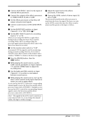
...0 NOISE REDUCTION SYSTEM REC PLAY REW FF STOP PAUSE 2 4 B A 3 5 97 0 1 Set the [INPUT-FLIP] switches on Input Channels 1-3 to "TAPE ( )", and the [INPUT-FLIP] switch on Tracks 1-3 to "MIC/LINE ( )". Set the [REC SELECT] switches on Input Channel 4 to "OFF". -Owner's Manual The Track 4 REC SELECT indicator flashes, and the R channel of the Stereo bus signal is often used to free up tracks for more recording, since those original tracks are then used for Track 4. Track 1 A Track 2 B Track 3 C Track 4 The first recording, ( + Overdubbing) A B C A+B+C Ping-pong...
...0 NOISE REDUCTION SYSTEM REC PLAY REW FF STOP PAUSE 2 4 B A 3 5 97 0 1 Set the [INPUT-FLIP] switches on Input Channels 1-3 to "TAPE ( )", and the [INPUT-FLIP] switch on Tracks 1-3 to "MIC/LINE ( )". Set the [REC SELECT] switches on Input Channel 4 to "OFF". -Owner's Manual The Track 4 REC SELECT indicator flashes, and the R channel of the Stereo bus signal is often used to free up tracks for more recording, since those original tracks are then used for Track 4. Track 1 A Track 2 B Track 3 C Track 4 The first recording, ( + Overdubbing) A B C A+B+C Ping-pong...

Owner's Manual
Page 26
... R TAPE TAPE MIC/ LINE INPUT-FLIP PAN L R 10 9 8 7 6 5 4 3 2 1 0 Track 1 Track 2 Track 3 R Track 4 PHONES MONITOR OUT CUE bus STEREO 10 9 8 7 6 5 4 3 2 1 0 Stereo bus R Signal flow during ping-pong recording -Owner's Manual 25 3 Set the monitor select switch to 0. At this time, turn the CUE controls on Input Channels 1-3 all the way to the right (R). 7 Press the [REW] button to rewind the tape, and press the [PLAY] button to start ping-pong recording. 0 Press the [STOP] button to stop ping-pong recording, and rewind the tape...
... R TAPE TAPE MIC/ LINE INPUT-FLIP PAN L R 10 9 8 7 6 5 4 3 2 1 0 Track 1 Track 2 Track 3 R Track 4 PHONES MONITOR OUT CUE bus STEREO 10 9 8 7 6 5 4 3 2 1 0 Stereo bus R Signal flow during ping-pong recording -Owner's Manual 25 3 Set the monitor select switch to 0. At this time, turn the CUE controls on Input Channels 1-3 all the way to the right (R). 7 Press the [REW] button to rewind the tape, and press the [PLAY] button to start ping-pong recording. 0 Press the [STOP] button to stop ping-pong recording, and rewind the tape...

Owner's Manual
Page 30
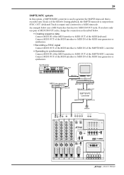
... MULTITRACK CASSETTE RECORDER +12 +6 +3 0 -5 -10 REC 1 2 3 4 L R TAPE SPEED CONTROL REC SELECT +12 PITCH 1 2 3 4 OFF OFF OFF OFF L R L R 4.8/ 9.5 10 - + +6 POWER +3 0 -5 -10 METER SELECT 4TR STEREO Effects processor connection with the [INPUT-FLIP] switch set to "TAPE ( )", effects are applied to the MIC/LINE INPUT 1 or 2 signal with an insert cable Once connected, operation is the same as normal recording and mixdown. For example, delay and reverb type effects with the AUX SENDs jacks, connect AUX...
... MULTITRACK CASSETTE RECORDER +12 +6 +3 0 -5 -10 REC 1 2 3 4 L R TAPE SPEED CONTROL REC SELECT +12 PITCH 1 2 3 4 OFF OFF OFF OFF L R L R 4.8/ 9.5 10 - + +6 POWER +3 0 -5 -10 METER SELECT 4TR STEREO Effects processor connection with the [INPUT-FLIP] switch set to "TAPE ( )", effects are applied to the MIC/LINE INPUT 1 or 2 signal with an insert cable Once connected, operation is the same as normal recording and mixdown. For example, delay and reverb type effects with the AUX SENDs jacks, connect AUX...
Owner's Manual
Page 32
... output only processed signals. 4 Connect sound sources to MIC/LINE INPUTs 1-4. 5 Set the [INPUT-FLIP] switches on Input Channels 1-4 to "MIC/LINE ( )". 6 Set the [REC SELECT] switch of effects changes. However, if you change the channel faders, the degree of a recording track to apply effects during normal recording. Note: The signals for recording. B Adjust the input level on Input Channels 1-4 to "CUE". When you are sourced post-fader. The processed sound from the effects units to the Stereo bus cannot be recorded. 7 Set...
... output only processed signals. 4 Connect sound sources to MIC/LINE INPUTs 1-4. 5 Set the [INPUT-FLIP] switches on Input Channels 1-4 to "MIC/LINE ( )". 6 Set the [REC SELECT] switch of effects changes. However, if you change the channel faders, the degree of a recording track to apply effects during normal recording. Note: The signals for recording. B Adjust the input level on Input Channels 1-4 to "CUE". When you are sourced post-fader. The processed sound from the effects units to the Stereo bus cannot be recorded. 7 Set...

Owner's Manual
Page 33
... processor so that it will be directly recorded on Track 4. 6 Turn up the CUE controls on Track 4 to " 4 ". The vocal will output only the processed signal. 2 Connect a vocal microphone to MIC/LINE INPUT 4. 3 Set the [INPUT-FLIP] switches on Input Channels 1-4 to "MIC/LINE ( )". 4 Set the [REC SELECT] switches on Tracks 1-3 to "OFF". 5 Set the [REC SELECT] switch on Input Channels 1-4. You can monitor the CUE bus signals (tape Tracks 1-3 and the dry vocal) mixed with reverb effects applied. The...
... processor so that it will be directly recorded on Track 4. 6 Turn up the CUE controls on Track 4 to " 4 ". The vocal will output only the processed signal. 2 Connect a vocal microphone to MIC/LINE INPUT 4. 3 Set the [INPUT-FLIP] switches on Input Channels 1-4 to "MIC/LINE ( )". 4 Set the [REC SELECT] switches on Tracks 1-3 to "OFF". 5 Set the [REC SELECT] switch on Input Channels 1-4. You can monitor the CUE bus signals (tape Tracks 1-3 and the dry vocal) mixed with reverb effects applied. The...
Owner's Manual
Page 38
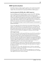
... Tracks 1-3 sounds with the MT400. During playback, the same device is stopped, the MIDI sequencer stops, too. Synchronizing the MT400 with a MIDI Sequencer To use the MT400 in a synchronized MIDI system, you need a device called an "MTC/SMPTE converter". When the MT400 is used to record a SYNC signal.) A SYNC signal is timing information in the form of the SYNC signal for operation. There are two major formats of the sequencer) into MTC or MIDI Clock signals. -Owner's Manual...
... Tracks 1-3 sounds with the MT400. During playback, the same device is stopped, the MIDI sequencer stops, too. Synchronizing the MT400 with a MIDI Sequencer To use the MT400 in a synchronized MIDI system, you need a device called an "MTC/SMPTE converter". When the MT400 is used to record a SYNC signal.) A SYNC signal is timing information in the form of the SYNC signal for operation. There are two major formats of the sequencer) into MTC or MIDI Clock signals. -Owner's Manual...
Owner's Manual
Page 40
... MIDI interface to R TAPE TAPE MIC/ LINE INPUT-FLIP LEVEL PAN PAN PAN PAN MIN MONITOR/PHONES STEREO ST+CUE CUE MAX L R L R L R L R 10 10 10 10 9 9 9 9 8 8 8 8 7 7 7 7 6 6 6 6 5 5 5 5 4 4 4 4 3 3 3 3 2 2 2 2 1 1 1 1 0 0 0 0 STEREO 10 9 8 7 6 5 4 3 2 1 0 NOISE REDUCTION SYSTEM REC PLAY REW FF STOP PAUSE -Owner's Manual If you have only one pair of MIDI IN/OUT jacks, change the connection as described below uses a MIDI interface that is output from SYNC OUT (dedicated Track 4 output) and converted to...
... MIDI interface to R TAPE TAPE MIC/ LINE INPUT-FLIP LEVEL PAN PAN PAN PAN MIN MONITOR/PHONES STEREO ST+CUE CUE MAX L R L R L R L R 10 10 10 10 9 9 9 9 8 8 8 8 7 7 7 7 6 6 6 6 5 5 5 5 4 4 4 4 3 3 3 3 2 2 2 2 1 1 1 1 0 0 0 0 STEREO 10 9 8 7 6 5 4 3 2 1 0 NOISE REDUCTION SYSTEM REC PLAY REW FF STOP PAUSE -Owner's Manual If you have only one pair of MIDI IN/OUT jacks, change the connection as described below uses a MIDI interface that is output from SYNC OUT (dedicated Track 4 output) and converted to...
Owner's Manual
Page 44
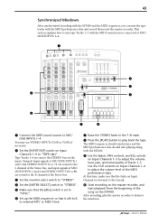
... STOP PAUSE 4 5 3 7 8 1 Connect the MIDI sound sources to "TAPE ( )". After recording, play back the tape. At this time, make sure that it will lock to external MTC or MIDI Clock. 7 Raise the STEREO fader to the 7-8 mark. 8 Press the [PLAY] button to play the master recorder to listen to the L channel of the MIDI performance data. Input signals at MIC/LINE INPUTs 1 and 3 and STEREO INPUT 5L or 7L are routed to the mixdown. -Owner's Manual...
... STOP PAUSE 4 5 3 7 8 1 Connect the MIDI sound sources to "TAPE ( )". After recording, play back the tape. At this time, make sure that it will lock to external MTC or MIDI Clock. 7 Raise the STEREO fader to the 7-8 mark. 8 Press the [PLAY] button to play the master recorder to listen to the L channel of the MIDI performance data. Input signals at MIC/LINE INPUTs 1 and 3 and STEREO INPUT 5L or 7L are routed to the mixdown. -Owner's Manual...

Owner's Manual
Page 45
...;culty operating the MT400 or it does not seem to the MIDI sequencer's user manual. -Owner's Manual The level meters do not indicate signal levels. Fluctuating output level. MIDI sequencer does not synchronize to a suitable AC wall outlet securely and plugged into MIDI Clock or MTC. Advice Make sure the AC adapter is set to "MIC/LINE ( )", raise the corresponding input channel fader and the STEREO fader, and set to convert the recorded SYNC signal...
...;culty operating the MT400 or it does not seem to the MIDI sequencer's user manual. -Owner's Manual The level meters do not indicate signal levels. Fluctuating output level. MIDI sequencer does not synchronize to a suitable AC wall outlet securely and plugged into MIDI Clock or MTC. Advice Make sure the AC adapter is set to "MIC/LINE ( )", raise the corresponding input channel fader and the STEREO fader, and set to convert the recorded SYNC signal...

