

Imx644 Manager Owner's Manual
Page 5
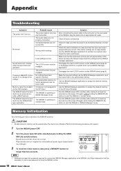
The "Device Manager" window will appear. Installing the IMX644 USB Driver (Windows 7 users) 1 Turn the IMX644 power switch OFF. 2 Turn the IMX644 ON while holding the front-panel MEMORY [D] button, then connect the IMX644 to the computer's USB connector. 3 Select [Start] → [Control Panel] → [Hardware and Sound] → [Device Manager]. IMX644 Manager Owner's Manual 5 The "Update Driver Software" window will appear. 4 Right click "YAMAHA IMX644" in "Other Devices", and select "Update Driver Software".
The "Device Manager" window will appear. Installing the IMX644 USB Driver (Windows 7 users) 1 Turn the IMX644 power switch OFF. 2 Turn the IMX644 ON while holding the front-panel MEMORY [D] button, then connect the IMX644 to the computer's USB connector. 3 Select [Start] → [Control Panel] → [Hardware and Sound] → [Device Manager]. IMX644 Manager Owner's Manual 5 The "Update Driver Software" window will appear. 4 Right click "YAMAHA IMX644" in "Other Devices", and select "Update Driver Software".

Imx644 Manager Owner's Manual
Page 7
...-panel MEMORY [D] button. IMX644 Manager Owner's Manual 7 Click [Close] to close the window, and check that "Yamaha IMX644 USB Serial Converter" has been added to the "Ports (COM & LPT)" item in "Other Devices", and select "Update Driver Software". If the installation has been successful the IMX644 Manager [Status] indicator will light green and the device will be online. Click [Close] to close the window, and check that "Yamaha IMX644 USB...
...-panel MEMORY [D] button. IMX644 Manager Owner's Manual 7 Click [Close] to close the window, and check that "Yamaha IMX644 USB Serial Converter" has been added to the "Ports (COM & LPT)" item in "Other Devices", and select "Update Driver Software". If the installation has been successful the IMX644 Manager [Status] indicator will light green and the device will be online. Click [Close] to close the window, and check that "Yamaha IMX644 USB...

Imx644 Manager Owner's Manual
Page 15
... Edit screen (BLOCK screen) will appear first. 1 2 3 4 1 [Parameter Edit] button This button opens the Parameter Edit screen, allowing you must power-off the IMX644 and then restart the IMX644 while holding down its MEMORY [D] button (IMX644 Manager mode). IMX644 Manager Owner's Manual 15 Starting IMX644 Manager NOTE • In order for the IMX644, and click the [OK] button. If you proceed. If you want to change the password, you'll need to switch connections...
... Edit screen (BLOCK screen) will appear first. 1 2 3 4 1 [Parameter Edit] button This button opens the Parameter Edit screen, allowing you must power-off the IMX644 and then restart the IMX644 while holding down its MEMORY [D] button (IMX644 Manager mode). IMX644 Manager Owner's Manual 15 Starting IMX644 Manager NOTE • In order for the IMX644, and click the [OK] button. If you proceed. If you want to change the password, you'll need to switch connections...

Imx644 Manager Owner's Manual
Page 19
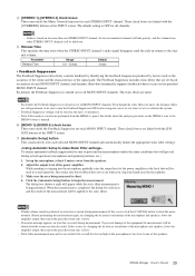
... red if the switch is ON. INPUT GAIN This adjusts the input gain. The range will appear first when you can edit the input gain for the head amp that appears. If excessive input level is ON. Click the [CLOSE] button to indicate excessive input level. This screen will depend on each MONO INPUT channel. IMX644 Manager Owner's Manual 19 BLOCK screen This shows a block diagram of the entire signal route from input to output, and allows you...
... red if the switch is ON. INPUT GAIN This adjusts the input gain. The range will appear first when you can edit the input gain for the head amp that appears. If excessive input level is ON. Click the [CLOSE] button to indicate excessive input level. This screen will depend on each MONO INPUT channel. IMX644 Manager Owner's Manual 19 BLOCK screen This shows a block diagram of the entire signal route from input to output, and allows you...
Imx644 Manager Owner's Manual
Page 21
... IMX644's volume knob settings. The initial setting is output to the main speaker outputs so that the sound from off , the volume will only be as a distance (meters) at the speed of the 6-band equalizers provided for each OUTPUT channel. Click the [CLOSE] button to the starting screen. Distance indication This indicates the specified delay time as specified by its LOCK switch. If this is locked by the on-screen faders; Fader This adjusts the volume...
... IMX644's volume knob settings. The initial setting is output to the main speaker outputs so that the sound from off , the volume will only be as a distance (meters) at the speed of the 6-band equalizers provided for each OUTPUT channel. Click the [CLOSE] button to the starting screen. Distance indication This indicates the specified delay time as specified by its LOCK switch. If this is locked by the on-screen faders; Fader This adjusts the volume...

Imx644 Manager Owner's Manual
Page 22
..., where you can adjust the volume balance between outputs A/B (L/R) of the level meter lights red, or if the PEAK indicator lights red, the output signal level is shipped from the factory. left button Press (hold down the mouse button to that button will be recalled and the parameter settings will be switched accordingly. IMX644 Manager Owner's Manual 22 Press (hold) the left -click and hold ) the right button ! Memories A through D all contain...
..., where you can adjust the volume balance between outputs A/B (L/R) of the level meter lights red, or if the PEAK indicator lights red, the output signal level is shipped from the factory. left button Press (hold down the mouse button to that button will be recalled and the parameter settings will be switched accordingly. IMX644 Manager Owner's Manual 22 Press (hold) the left -click and hold ) the right button ! Memories A through D all contain...
Imx644 Manager Owner's Manual
Page 29
... dynamic filters are linked with the [OVERRIDE] buttons of each selected MONO INPUT channel and automatically makes the appropriate static filter settings. These check boxes are still operational so be sure to the level that will prevail during actual operation (microphone and speaker positions, etc.). 1. While speaking or singing into the microphone gradually raise the output level of the power amplifier to turn on/off the Music Override function for all channels. 4 [STEREO 1]-[STEREO...
... dynamic filters are linked with the [OVERRIDE] buttons of each selected MONO INPUT channel and automatically makes the appropriate static filter settings. These check boxes are still operational so be sure to the level that will prevail during actual operation (microphone and speaker positions, etc.). 1. While speaking or singing into the microphone gradually raise the output level of the power amplifier to turn on/off the Music Override function for all channels. 4 [STEREO 1]-[STEREO...
Imx644 Manager Owner's Manual
Page 30
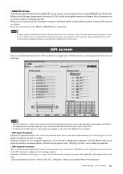
... GPI (General Purpose Interface), used to change to each memory. • MEMORY Assign Of the sixteen memories specified in the MEMORY screen, any four can edit the name of the output port. When you to input and output control signals. If you want to make an assignment. • GPI Output Terminal Here you select a button to more than one of the rear-panel GPI input ports recalls the assigned memory. IMX644 Manager Owner's Manual 30
... GPI (General Purpose Interface), used to change to each memory. • MEMORY Assign Of the sixteen memories specified in the MEMORY screen, any four can edit the name of the output port. When you to input and output control signals. If you want to make an assignment. • GPI Output Terminal Here you select a button to more than one of the rear-panel GPI input ports recalls the assigned memory. IMX644 Manager Owner's Manual 30

Owner's Manual
Page 2
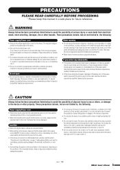
... branch (circuit breaker or fuse) circuits or install AC line filter/s. The above statements apply ONLY to those products distributed by Yamaha Corporation of Graphical Symbols The lightning flash with dry cloth. 7 Do not block any way, such as indicated in the instructions contained in the users manual, may be determined by turning the unit "OFF" and...
... branch (circuit breaker or fuse) circuits or install AC line filter/s. The above statements apply ONLY to those products distributed by Yamaha Corporation of Graphical Symbols The lightning flash with dry cloth. 7 Do not block any way, such as indicated in the instructions contained in the users manual, may be determined by turning the unit "OFF" and...
Owner's Manual
Page 3
... on page 7. Depending on , trip over, or roll anything over . • Do not block the vents. Inadequate ventilation can result in an unstable position where it . (5)-6 1/2 3 IMX644 Owner's Manual Pulling by qualified Yamaha service personnel. • Never insert or remove an electric plug with a protective grounding connection. Then have it . If it should appear to prevent the...
... on page 7. Depending on , trip over, or roll anything over . • Do not block the vents. Inadequate ventilation can result in an unstable position where it . (5)-6 1/2 3 IMX644 Owner's Manual Pulling by qualified Yamaha service personnel. • Never insert or remove an electric plug with a protective grounding connection. Then have it . If it should appear to prevent the...

Owner's Manual
Page 4
... time without turning on the power until the condensation has completely dried out. • Do not insert your plug proceed as switches, volume controls, and connectors, deteriorates over time. If there is suspected. * This applies only to products distributed by the safety earth symbol or colored GREEN or GREEN-andYELLOW. Consult qualifi ed Yamaha service personnel about replacing defective components. See user manual instructions...
... time without turning on the power until the condensation has completely dried out. • Do not insert your plug proceed as switches, volume controls, and connectors, deteriorates over time. If there is suspected. * This applies only to products distributed by the safety earth symbol or colored GREEN or GREEN-andYELLOW. Consult qualifi ed Yamaha service personnel about replacing defective components. See user manual instructions...

Owner's Manual
Page 6
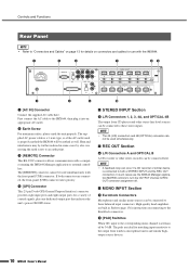
... be directly recalled via front-panel MEMORY [A] through [D] buttons. ■ Optical Digital I/O Connecting to compatible devices (CD and DVD players, for example) via the optical digital interface allows accurate signal transfer with clear imaging and optimum overall sound quality throughout the listening area. Four of applications: six mono inputs, four stereo inputs, two stereo outputs, two mono outputs, and one dedicated stereo output for recording. ■ 16 Memories Up to a specified mono input channel...
... be directly recalled via front-panel MEMORY [A] through [D] buttons. ■ Optical Digital I/O Connecting to compatible devices (CD and DVD players, for example) via the optical digital interface allows accurate signal transfer with clear imaging and optimum overall sound quality throughout the listening area. Four of applications: six mono inputs, four stereo inputs, two stereo outputs, two mono outputs, and one dedicated stereo output for recording. ■ 16 Memories Up to a specified mono input channel...

Owner's Manual
Page 7
...: audio sources (microphones, CD players, etc.), IMX644, and finally power amplifiers. Before Operation ■ Connecting the AC Power Cable CAUTION • Before connecting the power cable, make sure the local supply voltage matches the rated AC voltage of the unit). ■ Powering ON or OFF CAUTION • To prevent loud noise bursts from the speakers when powering up and operating the IMX644 hardware. This manual describes the installation...
...: audio sources (microphones, CD players, etc.), IMX644, and finally power amplifiers. Before Operation ■ Connecting the AC Power Cable CAUTION • Before connecting the power cable, make sure the local supply voltage matches the rated AC voltage of the unit). ■ Powering ON or OFF CAUTION • To prevent loud noise bursts from the speakers when powering up and operating the IMX644 hardware. This manual describes the installation...

Owner's Manual
Page 8
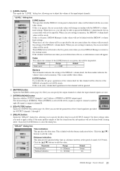
... 3 meters. • Before connecting the computer to the [USB] connector, exit from the device. • While the computer is recalled. The LOCK indicator lights red when the controls are locked. Press the [LOCK] switch a second time to unlock the controls and allow normal operation of a pen) to prevent further changes to the level or MEMORY settings. Controls and Functions Front Panel 1 3 6 9 )@ 24 5 7 8 ! # 1 [LOCK] Switch and Indicator The [LOCK] switch can be connected to the IMX644 via...
... 3 meters. • Before connecting the computer to the [USB] connector, exit from the device. • While the computer is recalled. The LOCK indicator lights red when the controls are locked. Press the [LOCK] switch a second time to unlock the controls and allow normal operation of a pen) to prevent further changes to the level or MEMORY settings. Controls and Functions Front Panel 1 3 6 9 )@ 24 5 7 8 ! # 1 [LOCK] Switch and Indicator The [LOCK] switch can be connected to the IMX644 via...

Owner's Manual
Page 9
... external controllers is also possible in the IMX644 unit itself, be recalled. If excessive input level is indicated either reduce the output level of the corresponding mono channels. ■ STEREO INPUT Section 6 Matrix Indicators The outputs to which each mono input are assigned are stored in this mode. # [POWER] Switch & Indicator Turns power to the unit ON or OFF. Level Knobs These knobs adjust the output level from the factory. • Switching Modes To start the unit in this mode. Settings...
... external controllers is also possible in the IMX644 unit itself, be recalled. If excessive input level is indicated either reduce the output level of the corresponding mono channels. ■ STEREO INPUT Section 6 Matrix Indicators The outputs to which each mono input are assigned are stored in this mode. # [POWER] Switch & Indicator Turns power to the unit ON or OFF. Level Knobs These knobs adjust the output level from the factory. • Switching Modes To start the unit in this mode. Settings...
Owner's Manual
Page 10
... use the IMX644 Manager application MATRIX controls to turn the OUTPUT channel to REC OUT connector assignment off. ■ MONO INPUT Section 7 Euroblock Connectors Microphones and similar mono sources can be earthed as well. Controls and Functions Rear Panel NOTE • Refer to "Connectors and Cables" on page 13 for details on connectors and cables for instructions on connecting to the Euroblock connectors. 8 [PAD] Switches When ON, input to the corresponding mono channel...
... use the IMX644 Manager application MATRIX controls to turn the OUTPUT channel to REC OUT connector assignment off. ■ MONO INPUT Section 7 Euroblock Connectors Microphones and similar mono sources can be earthed as well. Controls and Functions Rear Panel NOTE • Refer to "Connectors and Cables" on page 13 for details on connectors and cables for instructions on connecting to the Euroblock connectors. 8 [PAD] Switches When ON, input to the corresponding mono channel...
Owner's Manual
Page 11
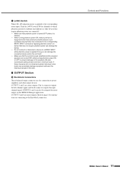
... other output devices. We also recommend setting all level controls to the Euroblock connectors. If these measures are not observed sudden high-level noise bursts can damage the device. • Do not connect or disconnect a device to the corresponding MONO INPUT connectors. Turn the [+48V] switch ON for instructions on connecting to minimum level. Applying phantom power to power amplifiers and other than phantom-powered devices such condenser microphones are connected. •...
... other output devices. We also recommend setting all level controls to the Euroblock connectors. If these measures are not observed sudden high-level noise bursts can damage the device. • Do not connect or disconnect a device to the corresponding MONO INPUT connectors. Turn the [+48V] switch ON for instructions on connecting to minimum level. Applying phantom power to power amplifiers and other than phantom-powered devices such condenser microphones are connected. •...

Owner's Manual
Page 16
... is Feedback Suppressor ON. Measurement from background music or other muted channels fades in and returns to 3 o'clock. 3 Set up the microphone at least 5 meters away from the speakers. 4 Adjust the output level of the MONO INPUT to which the microphone that is connected to the same output are ON for more than two seconds. trols to 3 o'clock. 2 Set the level control of the power amplifier. Also clap your...
... is Feedback Suppressor ON. Measurement from background music or other muted channels fades in and returns to 3 o'clock. 3 Set up the microphone at least 5 meters away from the speakers. 4 Adjust the output level of the MONO INPUT to which the microphone that is connected to the same output are ON for more than two seconds. trols to 3 o'clock. 2 Set the level control of the power amplifier. Also clap your...
Owner's Manual
Page 18
... assigned to the connector on . Solution After connecting the power cable to the GPI input. Disengage the main LOCK function via the IMX644 panel (page 8), or disengage LOCK for at least six seconds turn on the rear panel of the IMX644, plug the cable into an appropriate AC outlet. When initialization is complete the odd-numbered matrix input channel indicators will be necessary to set them to start the IMX644 in memory will light. 3 To recall...
... assigned to the connector on . Solution After connecting the power cable to the GPI input. Disengage the main LOCK function via the IMX644 panel (page 8), or disengage LOCK for at least six seconds turn on the rear panel of the IMX644, plug the cable into an appropriate AC outlet. When initialization is complete the odd-numbered matrix input channel indicators will be necessary to set them to start the IMX644 in memory will light. 3 To recall...

Owner's Manual
Page 21
... DC( phantom power ) is supplied to -15dBm *1 Connector OPTICAL Square *1 0dBm = 1mW CONTROL I/O CHARACTERISTICS GPI *1 REMOTE USB Terminal IN OUT POWER MONITOR OUTPUT Format Mechanical "make" contact - - For Use With Nominal 10kΩ Lines 10kΩ Lines Output level Nominal Max. Appendix General Specifications Signal Delay Dimensions (W x H x D) Net Weight Power Requirements Power Consumption Heat Dissipation Temperature range Included Accessories AC Power Cord Length Sampling Frequency External Clock Sampling Frequency Internal Clock 2.5ms (MONO INPUT [1-6] to OUTPUT...
... DC( phantom power ) is supplied to -15dBm *1 Connector OPTICAL Square *1 0dBm = 1mW CONTROL I/O CHARACTERISTICS GPI *1 REMOTE USB Terminal IN OUT POWER MONITOR OUTPUT Format Mechanical "make" contact - - For Use With Nominal 10kΩ Lines 10kΩ Lines Output level Nominal Max. Appendix General Specifications Signal Delay Dimensions (W x H x D) Net Weight Power Requirements Power Consumption Heat Dissipation Temperature range Included Accessories AC Power Cord Length Sampling Frequency External Clock Sampling Frequency Internal Clock 2.5ms (MONO INPUT [1-6] to OUTPUT...


