Owners Manual
Page 2
...and the like. 8 Accessories - Do not place this product from the wall outlet before the product is operated. 2 Retain Instructions - Power-supply cords should be adhered to the operating instructions. 12 Grounding or Polarization - Do not use this product near water - in the ...Instructions - Use only with arrowhead symbol, within the product's enclosure that they may expose you to replace your product dealer or local power company. If the plug should be retained for future reference. 3 Heed Warnings - Do not overload wall outlets, extension cords, or ...
...and the like. 8 Accessories - Do not place this product from the wall outlet before the product is operated. 2 Retain Instructions - Power-supply cords should be adhered to the operating instructions. 12 Grounding or Polarization - Do not use this product near water - in the ...Instructions - Use only with arrowhead symbol, within the product's enclosure that they may expose you to replace your product dealer or local power company. If the plug should be retained for future reference. 3 Heed Warnings - Do not overload wall outlets, extension cords, or ...
Owners Manual
Page 3
...power outlets that are covered by the operating instructions as recommended by the interference. If you can be sure the service technician has used replacement parts specified by a qualified technician to restore the product to its subsidiaries. d) If the product does not operate normally by Yamaha..., provides information with this indicates a need for the grounding electrode. Failure to follow instructions could void your authority, granted by Yamaha Corporation of America or its normal operation, e) If the product has been dropped or damaged in any service or repairs to this...
...power outlets that are covered by the operating instructions as recommended by the interference. If you can be sure the service technician has used replacement parts specified by a qualified technician to restore the product to its subsidiaries. d) If the product does not operate normally by Yamaha..., provides information with this indicates a need for the grounding electrode. Failure to follow instructions could void your authority, granted by Yamaha Corporation of America or its normal operation, e) If the product has been dropped or damaged in any service or repairs to this...
Owners Manual
Page 4
... clean, dry cloth. 12 Only voltage specified on the back of this unit is too late, YAMAHA and the Electronic Industries Association's Consumer Electronics Group recommend you to consume a very small quantity of power. The cabinet should never be opened for any reasons. 15 When not planning to liquid dripping or... It may cause fire, damage to the wall outlet, even if this unit, and/or personal injury. YAMAHA will not be held responsible for any service is not disconnected from the AC power source as long as they may cause fire, damage to set for long periods of this unit in...
... clean, dry cloth. 12 Only voltage specified on the back of this unit is too late, YAMAHA and the Electronic Industries Association's Consumer Electronics Group recommend you to consume a very small quantity of power. The cabinet should never be opened for any reasons. 15 When not planning to liquid dripping or... It may cause fire, damage to the wall outlet, even if this unit, and/or personal injury. YAMAHA will not be held responsible for any service is not disconnected from the AC power source as long as they may cause fire, damage to set for long periods of this unit in...
Owners Manual
Page 5
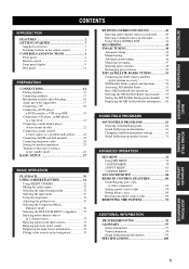
... player or an external decoder 22 Connecting a game console, a video camera or a portable audio player........... 22 Connecting the FM and AM antennas 23 Connecting the power cable 24 Setting the speaker impedance 25 Turning on this unit or setting it to the standby mode 26 BASIC SETUP 27 BASIC OPERATION PLAYBACK...
... player or an external decoder 22 Connecting a game console, a video camera or a portable audio player........... 22 Connecting the FM and AM antennas 23 Connecting the power cable 24 Setting the speaker impedance 25 Turning on this unit or setting it to the standby mode 26 BASIC SETUP 27 BASIC OPERATION PLAYBACK...
Owners Manual
Page 6
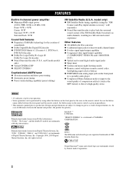
...XM name and related logos are trademarks of Digital Theater Systems, Inc. "Dolby", "Pro Logic", and the double-D symbol are registered trademarks of YAMAHA CORPORATION. Copyright 1996, 2003 Digital Theater Systems, Inc. "DTS", "DTS-ES", "NEO:6", and "DTS 96/24" are trademarks owned by ... ◆ Minimum RMS output power (0.06% THD, 20 Hz to 20 kHz, 8 Ω) Front: 90 W + 90 W Center: 90 W Surround: 90 W + 90 W Surround back: 90 W Sound field features ◆ Proprietary YAMAHA technology for your operation. • Some operations can be performed by Neural Audio Corporation. 2...
...XM name and related logos are trademarks of Digital Theater Systems, Inc. "Dolby", "Pro Logic", and the double-D symbol are registered trademarks of YAMAHA CORPORATION. Copyright 1996, 2003 Digital Theater Systems, Inc. "DTS", "DTS-ES", "NEO:6", and "DTS 96/24" are trademarks owned by ... ◆ Minimum RMS output power (0.06% THD, 20 Hz to 20 kHz, 8 Ω) Front: 90 W + 90 W Center: 90 W Surround: 90 W + 90 W Surround back: 90 W Sound field features ◆ Proprietary YAMAHA technology for your operation. • Some operations can be performed by Neural Audio Corporation. 2...
Owners Manual
Page 7
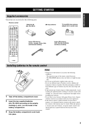
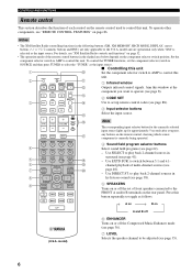
... new batteries, set up the remote control code and program any acquired functions that you notice the following parts. Remote control CODE SET TRANSMIT POWER TV POWER AV STANDBY POWER CD DVD MD CD-R CBL DTV SLEEP XM TUNER MULTI CH IN V-AUX DVR TV VOL TV CH AMP VOLUME SOURCE TV TV...
... new batteries, set up the remote control code and program any acquired functions that you notice the following parts. Remote control CODE SET TRANSMIT POWER TV POWER AV STANDBY POWER CD DVD MD CD-R CBL DTV SLEEP XM TUNER MULTI CH IN V-AUX DVR TV VOL TV CH AMP VOLUME SOURCE TV TV...
Owners Manual
Page 8
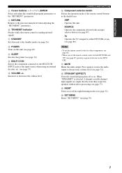
..., and DISPLAY) are operational only when "XM" is selected as the input source. Notes • In the standby mode, this unit consumes a small amount of power in order to adjust when "TUNER" is not selected as the input source (see page 45). • Adjusts the level of preset stations (see page...
..., and DISPLAY) are operational only when "XM" is selected as the input source. Notes • In the standby mode, this unit consumes a small amount of power in order to adjust when "TUNER" is not selected as the input source (see page 45). • Adjusts the level of preset stations (see page...
Owners Manual
Page 10
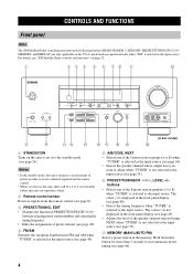
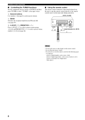
... IN C D component you press any buttons on the remote control, showing which source component is selected as follows: A on B on (U.S.A. Aim this 2 CODE SET TRANSMIT POWER POWER STANDBY POWER A unit. 1 Infrared window TV AV B Outputs infrared control signals. DISPLAY AUDIO G H I J Note The corresponding input selector button for the currently selected input source lights...
... IN C D component you press any buttons on the remote control, showing which source component is selected as follows: A on B on (U.S.A. Aim this 2 CODE SET TRANSMIT POWER POWER STANDBY POWER A unit. 1 Infrared window TV AV B Outputs infrared control signals. DISPLAY AUDIO G H I J Note The corresponding input selector button for the currently selected input source lights...
Owners Manual
Page 11
... multi-channel input signals are output directly from their respective speakers without effect processing (see page 87). C SLEEP Sets the sleep timer (see page 26). B POWER Turns on . Increases or decreases the volume level. CONTROLS AND FUNCTIONS F Component selector switch Selects the operation mode of the remote control buttons in the...
... multi-channel input signals are output directly from their respective speakers without effect processing (see page 87). C SLEEP Sets the sleep timer (see page 26). B POWER Turns on . Increases or decreases the volume level. CONTROLS AND FUNCTIONS F Component selector switch Selects the operation mode of the remote control buttons in the...
Owners Manual
Page 12
... TUNING MODE DISPLAY AUTO/MAN'L INPUT MULTI CH INPUT VOLUME VIDEO AUX VIDEO L AUDIO R PORTABLE Approximately 6 m (20 ft) 30 30 CODE SET TRANSMIT POWER TV POWER AV STANDBY POWER MD SLEEP CD CD-R XM CBL MULTI CH IN DVD DTV TUNER V-AUX DVR TV VOL TV CH AMP VOLUME SOURCE TV TV MUTE...
... TUNING MODE DISPLAY AUTO/MAN'L INPUT MULTI CH INPUT VOLUME VIDEO AUX VIDEO L AUDIO R PORTABLE Approximately 6 m (20 ft) 30 30 CODE SET TRANSMIT POWER TV POWER AV STANDBY POWER MD SLEEP CD CD-R XM CBL MULTI CH IN DVD DTV TUNER V-AUX DVR TV VOL TV CH AMP VOLUME SOURCE TV TV MUTE...

Owners Manual
Page 15
... connection information. 4 SUBWOOFER OUTPUT jack See page 14 for connection information. 5 DIGITAL INPUT jacks See page 19 for connection information. 0 AC OUTLET(S) Use to supply power to your other audiovisual components. model) 0 7 COMPONENT VIDEO jacks See pages 18 and 19 for connection information. 8 Antenna terminals See page 23 for connection information...
... connection information. 4 SUBWOOFER OUTPUT jack See page 14 for connection information. 5 DIGITAL INPUT jacks See page 19 for connection information. 0 AC OUTLET(S) Use to supply power to your other audiovisual components. model) 0 7 COMPONENT VIDEO jacks See pages 18 and 19 for connection information. 8 Antenna terminals See page 23 for connection information...
Owners Manual
Page 22
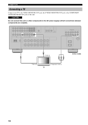
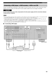
CAUTION Do not connect this unit or other components to the VIDEO MONITOR OUT jack, the S VIDEO MONITOR OUT jack or the COMPONENT VIDEO MONITOR OUT jacks of this unit. VIDEO MONITOR OUT S VIDEO MONITOR OUT COMPONENT VIDEO Y PB PR MONITOR OUT S S-video in TV 18 model) V Y PB PR Video in Component video in (U.S.A. CONNECTIONS Connecting a TV Connect your TV to the AC power supply until all connections between components are complete.
CAUTION Do not connect this unit or other components to the VIDEO MONITOR OUT jack, the S VIDEO MONITOR OUT jack or the COMPONENT VIDEO MONITOR OUT jacks of this unit. VIDEO MONITOR OUT S VIDEO MONITOR OUT COMPONENT VIDEO Y PB PR MONITOR OUT S S-video in TV 18 model) V Y PB PR Video in Component video in (U.S.A. CONNECTIONS Connecting a TV Connect your TV to the AC power supply until all connections between components are complete.
Owners Manual
Page 23
... (see page 18). The cable TV receiver and the satellite receiver are complete. CAUTION Do not connect this unit or other components to the AC power supply until all connections between components are examples of this unit, connect your other than the default component assigned to the VIDEO MONITOR OUT jack...
... (see page 18). The cable TV receiver and the satellite receiver are complete. CAUTION Do not connect this unit or other components to the AC power supply until all connections between components are examples of this unit, connect your other than the default component assigned to the VIDEO MONITOR OUT jack...
Owners Manual
Page 25
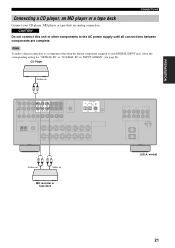
CAUTION Do not connect this unit or other than the default component assigned to the AC power supply until all connections between components are complete. CD Player Audio out RL AUDIO IN MD/ OUT CD (PLAY) CD-R (REC) DIGITAL INPUT DVD DTV/...
CAUTION Do not connect this unit or other than the default component assigned to the AC power supply until all connections between components are complete. CD Player Audio out RL AUDIO IN MD/ OUT CD (PLAY) CD-R (REC) DIGITAL INPUT DVD DTV/...
Owners Manual
Page 26
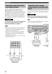
Be sure to match the left and right output jacks to the AC power supply until all connections between components are output only from a multi-format player, external decoder, sound processor or pre-amplifier. CAUTION Do not connect this ...
Be sure to match the left and right output jacks to the AC power supply until all connections between components are output only from a multi-format player, external decoder, sound processor or pre-amplifier. CAUTION Do not connect this ...
Owners Manual
Page 28
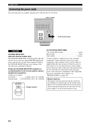
... General model .....110/120/220/230-240 V AC, 50/60 Hz VOLTAGE SELECTOR 230240V Voltage indication AC OUTLET(S) (SWITCHED) U.K. Voltages are complete, plug the power cable into the AC wall outlet. However, power to these outlet(s) is cut off when this unit is in the standby mode or the... of this unit must be set for more than one week. 24 For information on page 100. Power to these outlet(s) to supply power to these outlet(s). Rotate the VOLTAGE SELECTOR clockwise or counterclockwise to this unit is supplied when this unit and create a potential fire hazard. model) ...
... General model .....110/120/220/230-240 V AC, 50/60 Hz VOLTAGE SELECTOR 230240V Voltage indication AC OUTLET(S) (SWITCHED) U.K. Voltages are complete, plug the power cable into the AC wall outlet. However, power to these outlet(s) is cut off when this unit is in the standby mode or the... of this unit must be set for more than one week. 24 For information on page 100. Power to these outlet(s) to supply power to these outlet(s). Rotate the VOLTAGE SELECTOR clockwise or counterclockwise to this unit is supplied when this unit and create a potential fire hazard. model) ...
Owners Manual
Page 30
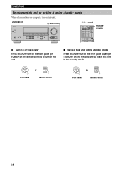
...INPUT MULTI CH INPUT VOLUME VIDEO AUX VIDEO L AUDIO R PORTABLE (U.S.A. STANDBY /ON POWER or Front panel Remote control STANDBY /ON STANDBY or Front panel Remote control 26 model) CODE SET TRANSMIT POWER TV POWER AV STANDBY POWER CD DVD MD CD-R CBL DTV SLEEP XM TUNER MULTI CH IN V-AUX DVR TV... VOL TV CH AMP VOLUME SOURCE TV STANDBY POWER ■ Turning on the power Press STANDBY/ON on the front panel (or POWER on the remote control) to turn on the remote control) to the standby mode. CONNECTIONS Turning on ...
...INPUT MULTI CH INPUT VOLUME VIDEO AUX VIDEO L AUDIO R PORTABLE (U.S.A. STANDBY /ON POWER or Front panel Remote control STANDBY /ON STANDBY or Front panel Remote control 26 model) CODE SET TRANSMIT POWER TV POWER AV STANDBY POWER CD DVD MD CD-R CBL DTV SLEEP XM TUNER MULTI CH IN V-AUX DVR TV... VOL TV CH AMP VOLUME SOURCE TV STANDBY POWER ■ Turning on the power Press STANDBY/ON on the front panel (or POWER on the remote control) to turn on the remote control) to the standby mode. CONNECTIONS Turning on ...
Owners Manual
Page 31
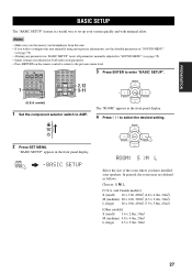
... ENTERTAIN MOVIE 2 3 4 STANDARD SELECT EXTD SUR. SET MENU MENU SRCH MODE .BASIC SETUP 3 Press ENTER to the previous menu level. 1 CODE SET TRANSMIT POWER TV POWER AV STANDBY POWER CD DVD MD CD-R CBL DTV SLEEP XM TUNER MULTI CH IN V-AUX DVR TV VOL TV CH AMP VOLUME SOURCE TV (U.S.A. ROOM: S >M L Select...
... ENTERTAIN MOVIE 2 3 4 STANDARD SELECT EXTD SUR. SET MENU MENU SRCH MODE .BASIC SETUP 3 Press ENTER to the previous menu level. 1 CODE SET TRANSMIT POWER TV POWER AV STANDBY POWER CD DVD MD CD-R CBL DTV SLEEP XM TUNER MULTI CH IN V-AUX DVR TV VOL TV CH AMP VOLUME SOURCE TV (U.S.A. ROOM: S >M L Select...
Owners Manual
Page 34
... MOVIE 2 3 4 STANDARD SELECT EXTD SUR. INPUT or CD DVD MD CD-R CBL DTV SLEEP XM TUNER MULTI CH IN 2 6 67 3 2 CODE SET TRANSMIT POWER TV POWER AV STANDBY POWER CD DVD MD CD-R CBL DTV SLEEP XM TUNER MULTI CH IN V-AUX DVR TV VOL TV CH AMP VOLUME SOURCE TV TV MUTE...
... MOVIE 2 3 4 STANDARD SELECT EXTD SUR. INPUT or CD DVD MD CD-R CBL DTV SLEEP XM TUNER MULTI CH IN 2 6 67 3 2 CODE SET TRANSMIT POWER TV POWER AV STANDBY POWER CD DVD MD CD-R CBL DTV SLEEP XM TUNER MULTI CH IN V-AUX DVR TV VOL TV CH AMP VOLUME SOURCE TV TV MUTE...
Owners Manual
Page 47
.... If you play back a video source that provides only an S-video or a composite video signal, you want to record from. 2 2 CODE SET TRANSMIT POWER TV POWER AV STANDBY POWER CD DVD MD CD-R CBL DTV SLEEP XM TUNER MULTI CH IN V-AUX DVR TV VOL TV CH AMP VOLUME SOURCE TV (U.S.A. STANDBY /ON...
.... If you play back a video source that provides only an S-video or a composite video signal, you want to record from. 2 2 CODE SET TRANSMIT POWER TV POWER AV STANDBY POWER CD DVD MD CD-R CBL DTV SLEEP XM TUNER MULTI CH IN V-AUX DVR TV VOL TV CH AMP VOLUME SOURCE TV (U.S.A. STANDBY /ON...


