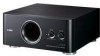

Owner's Manual
Page 2
... coloured RED. The exclamation point within an equilateral triangle is intended to alert you to qualified service personnel. MODEL: Serial No.: The serial number is connected to the terminal which is hazardous if engaged in your plug, proceed as follows: The wire which is coloured BLUE must be connected to the earth terminal of the obsolete outlet. 10 Protect the power cord from...
... coloured RED. The exclamation point within an equilateral triangle is intended to alert you to qualified service personnel. MODEL: Serial No.: The serial number is connected to the terminal which is hazardous if engaged in your plug, proceed as follows: The wire which is coloured BLUE must be connected to the earth terminal of the obsolete outlet. 10 Protect the power cord from...
Owner's Manual
Page 3
... held responsible for any modifications or alterations, unless authorised in all installation instructions. resident). resident.) 5. FCC INFORMATION (for parts or labour. This product, when installed as Yamaha may void your use the product. 2 IMPORTANT: When connecting this type of the original purchase. Modifications not expressly approved by the interference. Failure to follow instructions could void your sensitive hearing. This equipment generates/uses radio frequencies...
... held responsible for any modifications or alterations, unless authorised in all installation instructions. resident). resident.) 5. FCC INFORMATION (for parts or labour. This product, when installed as Yamaha may void your use the product. 2 IMPORTANT: When connecting this type of the original purchase. Modifications not expressly approved by the interference. Failure to follow instructions could void your sensitive hearing. This equipment generates/uses radio frequencies...
Owner's Manual
Page 4
... (i.e., unnatural, intermittent "rapping" or "hammering" sounds) coming from the bottom panel. Voltages are: 110-120/220-240 V AC, 50/60 Hz. 24 Secure placement or installation is still a chance that specified on switches, controls or connection wires. This unit features a magnetically shielded design, but there is the owner's responsibility. This unit is not disconnected from the wall outlet. 8 Since this unit has...
... (i.e., unnatural, intermittent "rapping" or "hammering" sounds) coming from the bottom panel. Voltages are: 110-120/220-240 V AC, 50/60 Hz. 24 Secure placement or installation is still a chance that specified on switches, controls or connection wires. This unit features a magnetically shielded design, but there is the owner's responsibility. This unit is not disconnected from the wall outlet. 8 Since this unit has...
Owner's Manual
Page 5
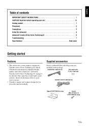
... IMPORTANT SAFETY INSTRUCTIONS i CAUTION: Read this unit horizontally. This super-bass sound adds a more realistic, theater-in the package. Supplied accessories Please confirm that the following items are included in -the-home effect to your stereo system. • Yamaha's unique and compact design let you place this before operating your unit iii Getting started 1 Placement 2 Connections 3 Using the subwoofer 5 Advanced Yamaha Active Servo Technology II 6 Troubleshooting 7 Specifications Back...
... IMPORTANT SAFETY INSTRUCTIONS i CAUTION: Read this unit horizontally. This super-bass sound adds a more realistic, theater-in the package. Supplied accessories Please confirm that the following items are included in -the-home effect to your stereo system. • Yamaha's unique and compact design let you place this before operating your unit iii Getting started 1 Placement 2 Connections 3 Using the subwoofer 5 Advanced Yamaha Active Servo Technology II 6 Troubleshooting 7 Specifications Back...
Owner's Manual
Page 6
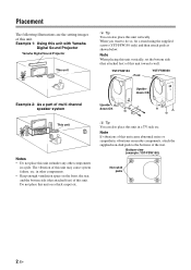
..., fix a stand using the supplied screws (YST-FSW150 only) and then attach pads as shown below. Note When placing this unit vertically, set the bottom side (that attached feet) of this unit cause abnormal noise or sympathetic vibrations on a thick carpet etc. Placement The following illustrations are the setting images of this unit toward a wall. YST-FSW150 Foot YST-FSW050 Example 2: As a part...
..., fix a stand using the supplied screws (YST-FSW150 only) and then attach pads as shown below. Note When placing this unit vertically, set the bottom side (that attached feet) of this unit cause abnormal noise or sympathetic vibrations on a thick carpet etc. Placement The following illustrations are the setting images of this unit toward a wall. YST-FSW150 Foot YST-FSW050 Example 2: As a part...
Owner's Manual
Page 7
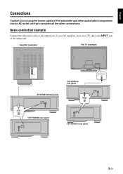
... connection example Connect the subwoofer cable to the output jack of your AV amplifier, receiver or TV and to the INPUT jack of the subwoofer and other audio/video components into an AC outlet until you complete all the other connections. Amplifier (example) Flat TV (example) YST-FSW150 rear panel INPUT SYSTEM CONNECTOR INPUT YST-FSW050 rear panel SYSTEM INPUT CONNECTOR SUBWOOFER YST-FSW150 rear panel INPUT SUBWOOFER INPUT SYSTEM CONNECTOR SYSTEM INPUT CONNECTOR YST-FSW050 rear panel 3 En English Connections Caution: Do not plug the power cables of the subwoofer...
... connection example Connect the subwoofer cable to the output jack of your AV amplifier, receiver or TV and to the INPUT jack of the subwoofer and other audio/video components into an AC outlet until you complete all the other connections. Amplifier (example) Flat TV (example) YST-FSW150 rear panel INPUT SYSTEM CONNECTOR INPUT YST-FSW050 rear panel SYSTEM INPUT CONNECTOR SUBWOOFER YST-FSW150 rear panel INPUT SUBWOOFER INPUT SYSTEM CONNECTOR SYSTEM INPUT CONNECTOR YST-FSW050 rear panel 3 En English Connections Caution: Do not plug the power cables of the subwoofer...
Owner's Manual
Page 8
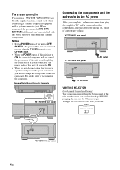
... control the power mode of appropriate voltage. VOLTAGE SELECTOR 220V-240V 110V-120V SYSTEM INPUT CONNECTOR YST-FSW050 rear panel 4 En For details, refer to OFF/ SYSTEM. Yamaha Digital Sound Projector (example) SYSTEM CONNECTOR YST-FSW150 rear panel INPUT SYSTEM CONNECTOR SYSTEM CONNECTOR Connecting the components and the subwoofer to the AC power After you need to ON, the connected component will always be set for your local main voltage BEFORE plugging this unit is set to change...
... control the power mode of appropriate voltage. VOLTAGE SELECTOR 220V-240V 110V-120V SYSTEM INPUT CONNECTOR YST-FSW050 rear panel 4 En For details, refer to OFF/ SYSTEM. Yamaha Digital Sound Projector (example) SYSTEM CONNECTOR YST-FSW150 rear panel INPUT SYSTEM CONNECTOR SYSTEM CONNECTOR Connecting the components and the subwoofer to the AC power After you need to ON, the connected component will always be set for your local main voltage BEFORE plugging this unit is set to change...
Owner's Manual
Page 9
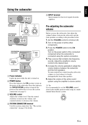
...10 YST-FSW150 rear panel INPUT SYSTEM CONNECTOR 5 INPUT 4 SYSTEM CONNECTOR YST-FSW050 rear panel SYSTEM INPUT CONNECTOR 1 Power indicator Lights up green while the unit is turned on. 2 POWER button Press this button to the OFF/SYSTEM position to turn on the power of the connected component when the subwoofer is connected using the amplifier's volume control. Turn on the power switch of the subwoofer. Pre-adjusting the subwoofer volume Before you use the system connection (see page 4). 3 VOLUME control Adjusts the volume level. To enjoy natural bass sound, keep...
...10 YST-FSW150 rear panel INPUT SYSTEM CONNECTOR 5 INPUT 4 SYSTEM CONNECTOR YST-FSW050 rear panel SYSTEM INPUT CONNECTOR 1 Power indicator Lights up green while the unit is turned on. 2 POWER button Press this button to the OFF/SYSTEM position to turn on the power of the connected component when the subwoofer is connected using the amplifier's volume control. Turn on the power switch of the subwoofer. Pre-adjusting the subwoofer volume Before you use the system connection (see page 4). 3 VOLUME control Adjusts the volume level. To enjoy natural bass sound, keep...
Owner's Manual
Page 10
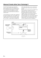
... negative impedance drive of view, the speaker impedance changes depending on the sound frequency. Cabinet High-amplitude bass sound Air woofer (Helmholtz resonator) Signals Active Servo Processing Port Amplifier Signals of the forces driving the amplifier and speakers. Yamaha's newly developed Advanced YST II, with less murkiness. From the amplifier's point of the amplifier and resonance generated between the amplifier and speaker, allowing accurate signal transmission and precise speaker control. Yamaha developed a new circuit...
... negative impedance drive of view, the speaker impedance changes depending on the sound frequency. Cabinet High-amplitude bass sound Air woofer (Helmholtz resonator) Signals Active Servo Processing Port Amplifier Signals of the forces driving the amplifier and speakers. Yamaha's newly developed Advanced YST II, with less murkiness. From the amplifier's point of the amplifier and resonance generated between the amplifier and speaker, allowing accurate signal transmission and precise speaker control. Yamaha developed a new circuit...
Owner's Manual
Page 11
Problem Power is not supplied even though the POWER button is set to (0). Sound level is not securely connected. Turn up the volume. Check the speaker mode setting on the component. 7 En If the problem you are playing a sound source that includes more bass frequencies. Cause Remedy The power plug is too low. Play a sound source that includes inadequate bass frequencies. Reposition the subwoofer, or break up the parallel wall surface by standing waves. Turn the POWER button to the...
Problem Power is not supplied even though the POWER button is set to (0). Sound level is not securely connected. Turn up the volume. Check the speaker mode setting on the component. 7 En If the problem you are playing a sound source that includes more bass frequencies. Cause Remedy The power plug is too low. Play a sound source that includes inadequate bass frequencies. Reposition the subwoofer, or break up the parallel wall surface by standing waves. Turn the POWER button to the...
Owner's Manual
Page 12
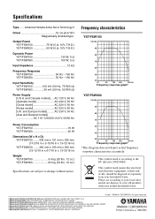
... depict actual frequency response characteristics accurately. YAMAHA CANADA MUSIC LTD. 135 MILNER AVE., SCARBOROUGH, ONTARIO M1S 3R1, CANADA YAMAHA ELECTRONIK EUROPA G.m.b.H. SIEMENSSTR. 22-34, 25462 RELLINGEN BEI HAMBURG, GERMANY YAMAHA ELECTRONIQUE FRANCE S.A. Advanced Yamaha Active Servo Technology II Driver 16 cm (6-5/16") Magnetically shielded type Output Power YST-FSW150 75 W (5 Ω, 10% T.H.D.) YST-FSW050 50 W (5 Ω, 10% T.H.D.) Dynamic Power YST-FSW150 130 W, 5 Ω YST-FSW050 100 W, 5 Ω Input Impedance 12 kΩ Frequency Response YST-FSW150...
... depict actual frequency response characteristics accurately. YAMAHA CANADA MUSIC LTD. 135 MILNER AVE., SCARBOROUGH, ONTARIO M1S 3R1, CANADA YAMAHA ELECTRONIK EUROPA G.m.b.H. SIEMENSSTR. 22-34, 25462 RELLINGEN BEI HAMBURG, GERMANY YAMAHA ELECTRONIQUE FRANCE S.A. Advanced Yamaha Active Servo Technology II Driver 16 cm (6-5/16") Magnetically shielded type Output Power YST-FSW150 75 W (5 Ω, 10% T.H.D.) YST-FSW050 50 W (5 Ω, 10% T.H.D.) Dynamic Power YST-FSW150 130 W, 5 Ω YST-FSW050 100 W, 5 Ω Input Impedance 12 kΩ Frequency Response YST-FSW150...


