

Owner's Manual
Page 2
... servicing to persons. Install in the space below. A polarized plug has two blades with dry cloth. 7 Do not block any heat sources such as power-supply cord or plug is located on or pinched particularly at plugs, convenience receptacles, and the point where they exit from tip-over. 13 Unplug this apparatus near any ventilation openings. NO USER-SERVICEABLE PARTS INSIDE. REFER SERVICING...
... servicing to persons. Install in the space below. A polarized plug has two blades with dry cloth. 7 Do not block any heat sources such as power-supply cord or plug is located on or pinched particularly at plugs, convenience receptacles, and the point where they exit from tip-over. 13 Unplug this apparatus near any ventilation openings. NO USER-SERVICEABLE PARTS INSIDE. REFER SERVICING...
Owner's Manual
Page 3
... device contains no user-serviceable parts. If you are not limited to, the following : Power supply/Power cord • Only use the speakers or headphones for extended periods of panel disfiguration or damage to prevent the internal temperature from the outlet. Then have the device inspected by qualified Yamaha service personnel. CAUTION Always follow the basic precautions listed below to avoid...
... device contains no user-serviceable parts. If you are not limited to, the following : Power supply/Power cord • Only use the speakers or headphones for extended periods of panel disfiguration or damage to prevent the internal temperature from the outlet. Then have the device inspected by qualified Yamaha service personnel. CAUTION Always follow the basic precautions listed below to avoid...

Owner's Manual
Page 4
... quality shielded cables. Use only Neutrik plugs (NL4) for information purposes only. XLR-type connectors are wired as indicated in the instructions contained in this manual, meets FCC requirements. IMPORTANT NOTICE FOR THE UNITED KINGDOM Connecting the Plug and Cord WARNING: THIS APPARATUS MUST BE EARTHED IMPORTANT. I Mixer Basics (starts on different branch (circuit breaker or fuse) circuits or install AC line fi...
... quality shielded cables. Use only Neutrik plugs (NL4) for information purposes only. XLR-type connectors are wired as indicated in the instructions contained in this manual, meets FCC requirements. IMPORTANT NOTICE FOR THE UNITED KINGDOM Connecting the Plug and Cord WARNING: THIS APPARATUS MUST BE EARTHED IMPORTANT. I Mixer Basics (starts on different branch (circuit breaker or fuse) circuits or install AC line fi...
Owner's Manual
Page 5
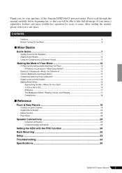
Contents Features ...6 Before Turning On the Mixer...6 I Reference Front & Rear Panels 19 Controls on Each Channel ...19 Digital Effects Section ...22 Master Section ...23 Rear Panel ...28 Speaker Connections 29 2-channel connection ...29 2-channel parallel connection ...29 Setting the GEQ with the FRC function 30 Rack Mounting 32 Setup ...33 Troubleshooting 34 Specifications 35 EMX5016CF Owner's Manual 5 After reading the manual, please store it in its Place 12 A Plethora of this Yamaha EMX5016CF powered mixer. Thank you will be able to take...
Contents Features ...6 Before Turning On the Mixer...6 I Reference Front & Rear Panels 19 Controls on Each Channel ...19 Digital Effects Section ...22 Master Section ...23 Rear Panel ...28 Speaker Connections 29 2-channel connection ...29 2-channel parallel connection ...29 Setting the GEQ with the FRC function 30 Rack Mounting 32 Setup ...33 Troubleshooting 34 Specifications 35 EMX5016CF Owner's Manual 5 After reading the manual, please store it in its Place 12 A Plethora of this Yamaha EMX5016CF powered mixer. Thank you will be able to take...
Owner's Manual
Page 6
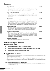
... noise from the speakers, you can cause it possible to connect the SPEAKERS jacks directly to freely mix inputs from the source (starting with the closest). The rear panel offers two types of the Stereo-bus signal output. For example: Sound source (external device) → EMX unit → Amps (Powered speakers) When turning power off . 6 EMX5016CF Owner's Manual After turning the unit OFF, wait for and removes feedback. Before Turning On the Mixer ■ Connecting to Power 1 Be sure that the POWER switch...
... noise from the speakers, you can cause it possible to connect the SPEAKERS jacks directly to freely mix inputs from the source (starting with the closest). The rear panel offers two types of the Stereo-bus signal output. For example: Sound source (external device) → EMX unit → Amps (Powered speakers) When turning power off . 6 EMX5016CF Owner's Manual After turning the unit OFF, wait for and removes feedback. Before Turning On the Mixer ■ Connecting to Power 1 Be sure that the POWER switch...

Owner's Manual
Page 7
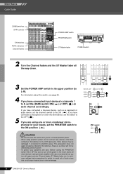
... electric instruments (such as a direct box, a preamp (guitar amp), or an amp simulator. RIGHT WRONG!! Then connect your input devices (microphones, instruments, etc.). Instead, these devices (including microphones) are using. Mixer Basics Quick Guide Mixer Basics Getting Sound to a single speaker. And before turning the power to the mixer. Input jacks SPEAKERS jacks 1 Connect up two speakers and generating some stereo output. Use non-powered speakers and dedicated speaker cable. EMX5016CF Owner's Manual 7 Connection of that operations and procedures will vary...
... electric instruments (such as a direct box, a preamp (guitar amp), or an amp simulator. RIGHT WRONG!! Then connect your input devices (microphones, instruments, etc.). Instead, these devices (including microphones) are using. Mixer Basics Quick Guide Mixer Basics Getting Sound to a single speaker. And before turning the power to the mixer. Input jacks SPEAKERS jacks 1 Connect up two speakers and generating some stereo output. Use non-powered speakers and dedicated speaker cable. EMX5016CF Owner's Manual 7 Connection of that operations and procedures will vary...
Owner's Manual
Page 8
... output controls (Channel faders, ST Master fader, etc.) to minimum settings before operating the switch, to the ON ( ). We also recommend that you turn off if you have connected a line-level device, such as these will not be affected by phantom power. • To protect your inputs, set the channel's switch to avoid risk of loud noises that could cause hearing loss or device damage. 8 EMX5016CF Owner's Manual Mixer Basics Quick Guide [26dB] switches GAIN controls ON switches PEAK indicators Channel faders POWER AMP switch PHANTOM switch...
... output controls (Channel faders, ST Master fader, etc.) to minimum settings before operating the switch, to the ON ( ). We also recommend that you turn off if you have connected a line-level device, such as these will not be affected by phantom power. • To protect your inputs, set the channel's switch to avoid risk of loud noises that could cause hearing loss or device damage. 8 EMX5016CF Owner's Manual Mixer Basics Quick Guide [26dB] switches GAIN controls ON switches PEAK indicators Channel faders POWER AMP switch PHANTOM switch...
Owner's Manual
Page 9
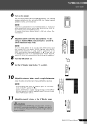
... maximum input level. 8 NOTE To use the LEVEL meter to view the level being input to the internal amp: Set the ST/AFL-PFL switch to ST( ). • Use the LIMITER lamps to all occupied channels. ered speakers) 7 Adjust the GAIN control for clipping of the ST Master fader. Note that these on the power to check for each channel you can monitor these signals through the headphones. EMX5016CF Owner's Manual 9 Mixer Basics Quick Guide 10 Adjust the channel faders on all connected devices...
... maximum input level. 8 NOTE To use the LEVEL meter to view the level being input to the internal amp: Set the ST/AFL-PFL switch to ST( ). • Use the LIMITER lamps to all occupied channels. ered speakers) 7 Adjust the GAIN control for clipping of the ST Master fader. Note that these on the power to check for each channel you can monitor these signals through the headphones. EMX5016CF Owner's Manual 9 Mixer Basics Quick Guide 10 Adjust the channel faders on all connected devices...

Owner's Manual
Page 10
... Quick Guide Adding Some Reverb You can use the PARAMETER knob to adjust the characteristic sound of a concert hall or jazz club. Note that you can use a separately sold FC5 foot switch to adjust the overall effect depth. As an alternative to the ON switch, you have selected a reverb effect, the knob adjusts the reverb time. 10 EMX5016CF Owner's Manual EFF1 knobs PROGRAM dial EFF1 ON switch EFF1 RTN fader 1 Turn the EFFECT1 PROGRAM...
... Quick Guide Adding Some Reverb You can use the PARAMETER knob to adjust the characteristic sound of a concert hall or jazz club. Note that you can use a separately sold FC5 foot switch to adjust the overall effect depth. As an alternative to the ON switch, you have selected a reverb effect, the knob adjusts the reverb time. 10 EMX5016CF Owner's Manual EFF1 knobs PROGRAM dial EFF1 ON switch EFF1 RTN fader 1 Turn the EFFECT1 PROGRAM...
Owner's Manual
Page 19
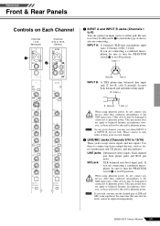
... not be adjusted independently. MIC jack: XLR balanced mic-level input jack. Other devices may be damaged if connected to phantom power. EMX5016CF Owner's Manual 19 Cold (-) Ground Hot (+) INPUT B: A TRS phone-type balanced line input jack (T: hot, R: cold, S: ground). NOTE On any given channel, you may use either jack. LINE jacks: Unbalanced stereo inputs. Reference Reference Front & Rear Panels Controls on each channel. 2 LINE/MIC Jacks (Channels 9/10 to 15/16) These jacks accept stereo inputs and mic inputs. Be sure to set the [26 dB] switch 4 to...
... not be adjusted independently. MIC jack: XLR balanced mic-level input jack. Other devices may be damaged if connected to phantom power. EMX5016CF Owner's Manual 19 Cold (-) Ground Hot (+) INPUT B: A TRS phone-type balanced line input jack (T: hot, R: cold, S: ground). NOTE On any given channel, you may use either jack. LINE jacks: Unbalanced stereo inputs. Reference Reference Front & Rear Panels Controls on each channel. 2 LINE/MIC Jacks (Channels 9/10 to 15/16) These jacks accept stereo inputs and mic inputs. Be sure to set the [26 dB] switch 4 to...
Owner's Manual
Page 20
... The -60 to the channel. Reference Front & Rear Panels Channels 1 to 8 (Monaural) 3 4 5 6 7 8 Channels 9/10 to 15/16 (Stereo) 5 6 8 9 9 0 0 A A B B C C D D E E F F G G 20 EMX5016CF Owner's Manual 3 INSERT I/O Jack (Channels 1 to 8) Each of these jacks to connect channels to devices such as a keyboard or audio device, set the switch to OFF ( ). 5 GAIN Control Adjusts the gain applied to the input signal level. To the input jack of the external processor To the INSERT I /O jack requires a special separately-sold insertion cable-such as the Yamaha YIC025, YIC050, or...
... The -60 to the channel. Reference Front & Rear Panels Channels 1 to 8 (Monaural) 3 4 5 6 7 8 Channels 9/10 to 15/16 (Stereo) 5 6 8 9 9 0 0 A A B B C C D D E E F F G G 20 EMX5016CF Owner's Manual 3 INSERT I/O Jack (Channels 1 to 8) Each of these jacks to connect channels to devices such as a keyboard or audio device, set the switch to OFF ( ). 5 GAIN Control Adjusts the gain applied to the input signal level. To the input jack of the external processor To the INSERT I /O jack requires a special separately-sold insertion cable-such as the Yamaha YIC025, YIC050, or...
Owner's Manual
Page 21
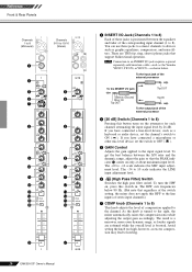
... use the PRE switch 0 to feed the channel's pre-fader signal into the Stereo, AUX, and EFFECT buses. B PAN Control (Channels 1 to adjust the volume balance among the various channels. NOTE To reduce noise, turn on , the mixer feeds the pre-fader signal to turn off . • The PFL (F, M, i) and AFL j switches select the mix to the AUX1/2 buses. F PFL (Pre-Fader Listen) Switch Set this switch on .) Be sure to the buses. Reference Front & Rear Panels 8 Equalizer (HIGH, MID, and LOW...
... use the PRE switch 0 to feed the channel's pre-fader signal into the Stereo, AUX, and EFFECT buses. B PAN Control (Channels 1 to adjust the volume balance among the various channels. NOTE To reduce noise, turn on , the mixer feeds the pre-fader signal to turn off . • The PFL (F, M, i) and AFL j switches select the mix to the AUX1/2 buses. F PFL (Pre-Fader Listen) Switch Set this switch on .) Be sure to the buses. Reference Front & Rear Panels 8 Equalizer (HIGH, MID, and LOW...

Owner's Manual
Page 22
..., to connect to an effector or to the PHONES jack. To set the switch on or off . I J J K K L L M M N N 22 EMX5016CF Owner's Manual H SEND Jacks • EFF1, EFF2 These unbalanced phone output jacks output the signal from the internal digital effect signal (pre the EFF1/2 RTN faders) into a LINE jack on each effect type. K AUX1/2 Knobs Each knob adjusts the level of effect from an external effector into the PFL bus, so that it can use of the effect types, refer...
..., to connect to an effector or to the PHONES jack. To set the switch on or off . I J J K K L L M M N N 22 EMX5016CF Owner's Manual H SEND Jacks • EFF1, EFF2 These unbalanced phone output jacks output the signal from the internal digital effect signal (pre the EFF1/2 RTN faders) into a LINE jack on each effect type. K AUX1/2 Knobs Each knob adjusts the level of effect from an external effector into the PFL bus, so that it can use of the effect types, refer...

Owner's Manual
Page 23
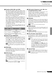
... phone jacks output the mixed stereo signal (L and R), where the level is adjusted by the ST Q SUB OUT control g. S PHONES Jack Connector for connection to indicate a value of the stereo-bus signal output at the external recording device side. T LAMP Jack This XLR 3 pin-type output jack is not connected. Pin 1 is for headphones. This 9-band GEQ adjusts the frequency characteristics of +1.5dB.) W GEQ ON Switch This switch toggles the graphic equalizer on . V GEQ +/- EMX5016CF Owner's Manual 23...
... phone jacks output the mixed stereo signal (L and R), where the level is adjusted by the ST Q SUB OUT control g. S PHONES Jack Connector for connection to indicate a value of the stereo-bus signal output at the external recording device side. T LAMP Jack This XLR 3 pin-type output jack is not connected. Pin 1 is for headphones. This 9-band GEQ adjusts the frequency characteristics of +1.5dB.) W GEQ ON Switch This switch toggles the graphic equalizer on . V GEQ +/- EMX5016CF Owner's Manual 23...

Owner's Manual
Page 26
... ST master fader. NOTE The PFL (F, M, i) and AFL j switches select the mix to be affected by turning on , the mixer supplies DC +48V power to AFL-PFL ( ), the LEVEL meters show the level output at the ST OUT jacks following adjustment by the PHONES control. NOTE Has no effect on channels 9/10 to the XLR input jacks. Note that the mute does not work on the output from the PHONES jack S. The indicator lights...
... ST master fader. NOTE The PFL (F, M, i) and AFL j switches select the mix to be affected by turning on , the mixer supplies DC +48V power to AFL-PFL ( ), the LEVEL meters show the level output at the ST OUT jacks following adjustment by the PHONES control. NOTE Has no effect on channels 9/10 to the XLR input jacks. Note that the mute does not work on the output from the PHONES jack S. The indicator lights...

Owner's Manual
Page 30
Controls Settings [26dB] switch Proper level* GAIN control Proper level* switch Off COMP knob 0 HIGH 0dB MID F - AUX2 knob - At this time, the GEQ display indications flash. switches. Noise Generator STEREO L FRC Noise R Measurement ST OUT L R [Block Diagram of Noise Measurement] 1 Connect the EMX to adjust the pink noise output level. The indicator begins flashing quickly, and measurement of the frequency characteristics starts. 4 Adjust the ST Master fader to a set to three seconds. To adjust the channel 1 input level, turn on the GEQ...
Controls Settings [26dB] switch Proper level* GAIN control Proper level* switch Off COMP knob 0 HIGH 0dB MID F - AUX2 knob - At this time, the GEQ display indications flash. switches. Noise Generator STEREO L FRC Noise R Measurement ST OUT L R [Block Diagram of Noise Measurement] 1 Connect the EMX to adjust the pink noise output level. The indicator begins flashing quickly, and measurement of the frequency characteristics starts. 4 Adjust the ST Master fader to a set to three seconds. To adjust the channel 1 input level, turn on the GEQ...

Owner's Manual
Page 31
... CD player, turn on the GEQ display every five seconds after measurement starts. 6 Confirm that the measurement result is muted during the suspension. To resume the measurement, press the MEASURE/CORRECT switch again. 7 Turn off . Sound Source EFFECT1 EFFECT2 FRC Music Playback Measurement ST OUT L R [Block Diagram of Music Playback Measurement] 1 Connect the EMX to a set the channel faders to a USER switch. The MEASURE/CORRECT switch indicator...
... CD player, turn on the GEQ display every five seconds after measurement starts. 6 Confirm that the measurement result is muted during the suspension. To resume the measurement, press the MEASURE/CORRECT switch again. 7 Turn off . Sound Source EFFECT1 EFFECT2 FRC Music Playback Measurement ST OUT L R [Block Diagram of Music Playback Measurement] 1 Connect the EMX to a set the channel faders to a USER switch. The MEASURE/CORRECT switch indicator...
Owner's Manual
Page 33
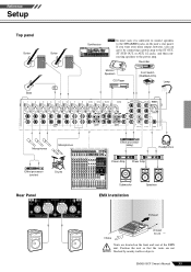
Recorder Monitor Speakers CD Player Foot Switch (YAMAHA FC5) Lamp Microphones Microphones Effect processor (exciter) Drums Rear Panel Effect processor (delay) Power Amp Power Amp Headphones Subwoofer EMX Installation Speakers Exhaust Intake At least 30 cm Vents are not CAUTION blocked by connecting a power amp to connect speakers OCTAVE DOWN UP Synthesizer PAN / SEND ASSIGN TONE KNOB CONTROL FUNCTION ÊARP FX EQ ASSIGN A PAN CUTOFF SWING ASSIGN B REVERB RESONANCE GATE TIME ASSIGN 1 CHORUS ATTACK VELOCITY ASSIGN 2 TEMPO RELEASE UNITMULTIPLY KN 1 LOW VOLUME...
Recorder Monitor Speakers CD Player Foot Switch (YAMAHA FC5) Lamp Microphones Microphones Effect processor (exciter) Drums Rear Panel Effect processor (delay) Power Amp Power Amp Headphones Subwoofer EMX Installation Speakers Exhaust Intake At least 30 cm Vents are not CAUTION blocked by connecting a power amp to connect speakers OCTAVE DOWN UP Synthesizer PAN / SEND ASSIGN TONE KNOB CONTROL FUNCTION ÊARP FX EQ ASSIGN A PAN CUTOFF SWING ASSIGN B REVERB RESONANCE GATE TIME ASSIGN 1 CHORUS ATTACK VELOCITY ASSIGN 2 TEMPO RELEASE UNITMULTIPLY KN 1 LOW VOLUME...
Owner's Manual
Page 34
... channels you are using the supplied power cord, and that it may cut off the output to cool down . ers set to initialize the GEQ and digital effect settings. ❑ Turning on the power while holding the GEQ ON switch and MAXIMIZE ON switch restores the initial factory settings for GEQ, Effects, Feedback Suppressor, and MAXIMIZE. 34 EMX5016CF Owner's Manual I No sound. ❑ Are microphones, external devices, and speakers connected correctly? ❑ Are the GAIN controls, channel faders, ST master fader...
... channels you are using the supplied power cord, and that it may cut off the output to cool down . ers set to initialize the GEQ and digital effect settings. ❑ Turning on the power while holding the GEQ ON switch and MAXIMIZE ON switch restores the initial factory settings for GEQ, Effects, Feedback Suppressor, and MAXIMIZE. 34 EMX5016CF Owner's Manual I No sound. ❑ Are microphones, external devices, and speakers connected correctly? ❑ Are the GAIN controls, channel faders, ST master fader...

Owner's Manual
Page 35
Compressor (COMP) PEAK Indicator SIGNAL Indicator STANDBY Switch Level Meter CH 1-15/16 XLR HIGH MID (MONO) MID (ST) LOW CH1-8 ST, PFL/AFL Digital Graphic Equalizer ST OUT Frequency Response Correction (FRC) System Feedback Suppressor (FBS) MAXIMIZE Digital Effect Lamp Maximum Output Power Select Switch Power Amplifier Signal Select Switch Yamaha Speaker Processing SPEAKERS Power Amplifier Protection Power Supply Protection Cooling Power Consumption AC Cord Dimensions Net Weight Conditions MIN TYP...
Compressor (COMP) PEAK Indicator SIGNAL Indicator STANDBY Switch Level Meter CH 1-15/16 XLR HIGH MID (MONO) MID (ST) LOW CH1-8 ST, PFL/AFL Digital Graphic Equalizer ST OUT Frequency Response Correction (FRC) System Feedback Suppressor (FBS) MAXIMIZE Digital Effect Lamp Maximum Output Power Select Switch Power Amplifier Signal Select Switch Yamaha Speaker Processing SPEAKERS Power Amplifier Protection Power Supply Protection Cooling Power Consumption AC Cord Dimensions Net Weight Conditions MIN TYP...


