
Owner's Manual
Page 2
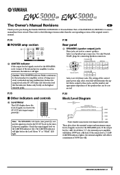
...Manual Revisions E Thank you for connecting Speakon connectors. P.18 Rear panel 3 SPEAKERS (speaker output) jacks These jacks are Speakon-type connectors. Use only Neutrik NL4FC plugs for purchasing the Yamaha EMX5000-20/EMX5000-12 Powered Mixer. CHANNEL A STEREO/PARALLEL 2- 1+ A+ 2+ 1- Neutrik NL4FC CHANNEL B 1+ B+ 1- Jacks 2 are 1/4"phone jacks.... diagram (bottom right) These plots show the nominal output and maximum output levels of the EMX5000-20, EMX5000-12 owner's manual have been revised. If the output level is being excessively overloaded and may malfunction.
...Manual Revisions E Thank you for connecting Speakon connectors. P.18 Rear panel 3 SPEAKERS (speaker output) jacks These jacks are Speakon-type connectors. Use only Neutrik NL4FC plugs for purchasing the Yamaha EMX5000-20/EMX5000-12 Powered Mixer. CHANNEL A STEREO/PARALLEL 2- 1+ A+ 2+ 1- Neutrik NL4FC CHANNEL B 1+ B+ 1- Jacks 2 are 1/4"phone jacks.... diagram (bottom right) These plots show the nominal output and maximum output levels of the EMX5000-20, EMX5000-12 owner's manual have been revised. If the output level is being excessively overloaded and may malfunction.
Owner's Manual
Page 4
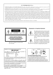
...(servicing) instructions in the mains lead of other electronic devices. When connecting an external wire to eliminate the problem by Yamaha Corporation of Graphical Symbols The lightning flash with arrowhead symbol within an equilateral triangle is marked with the letter N or ...frequencies and, if not installed and used . European Specifications Only This mark indicates a dangerous electrically live terminal. NO USER-SERVICEABLE PARTS INSIDE. Cable/s supplied with the requirements listed in such a way that your authority, granted by Yamaha may be made simply and without...
...(servicing) instructions in the mains lead of other electronic devices. When connecting an external wire to eliminate the problem by Yamaha Corporation of Graphical Symbols The lightning flash with arrowhead symbol within an equilateral triangle is marked with the letter N or ...frequencies and, if not installed and used . European Specifications Only This mark indicates a dangerous electrically live terminal. NO USER-SERVICEABLE PARTS INSIDE. Cable/s supplied with the requirements listed in such a way that your authority, granted by Yamaha may be made simply and without...
Owner's Manual
Page 5
...to this unit are a fire hazard. • To relocate the unit, turn off . Never pull the cord. Do not block them. Use the correct connecting cables and connect as inside this unit. Maintenance • Clean the contacts of the phone plug before turning on a power cord ... not use this unit away from the AC outlet. A damaged power cord is a fire and electrical shock hazard. • If lightning begins to amplifier outputs. A sudden blast of the power cord. Dirty contacts may result. • Do not place a container with wet hands. EMX5000-20/EMX5000-12-Owner...
...to this unit are a fire hazard. • To relocate the unit, turn off . Never pull the cord. Do not block them. Use the correct connecting cables and connect as inside this unit. Maintenance • Clean the contacts of the phone plug before turning on a power cord ... not use this unit away from the AC outlet. A damaged power cord is a fire and electrical shock hazard. • If lightning begins to amplifier outputs. A sudden blast of the power cord. Dirty contacts may result. • Do not place a container with wet hands. EMX5000-20/EMX5000-12-Owner...
Owner's Manual
Page 6
... induce noise. 4 Precautions PRECAUTIONS FOR OPERATION - The rate of this unit may damage the speakers. Influence on the operating environment and is unavoidable. EMX5000-20/EMX5000-12-Owner's Manual Connector pin assignments • XLR-type connectors are wired as follows: pin 1: ground, pin 2: hot (+), and pin 3: cold... of components with other electronic devices • The digital circuits of deterioration depends on cell phone usage • Using a cell phone (mobile telephone) near this unit may induce a slight noise into nearby radios and TVs. If noise occurs...
... induce noise. 4 Precautions PRECAUTIONS FOR OPERATION - The rate of this unit may damage the speakers. Influence on the operating environment and is unavoidable. EMX5000-20/EMX5000-12-Owner's Manual Connector pin assignments • XLR-type connectors are wired as follows: pin 1: ground, pin 2: hot (+), and pin 3: cold... of components with other electronic devices • The digital circuits of deterioration depends on cell phone usage • Using a cell phone (mobile telephone) near this unit may induce a slight noise into nearby radios and TVs. If noise occurs...
Owner's Manual
Page 7
... to take full advantage of applications from installed systems to smallscale PA systems. • A two-channel power amp is very useful for purchasing the Yamaha EMX5000-20/EMX5000-12 Powered Mixer. Contents Introduction 5 Features 5 EMX5000-20/EMX5000-12 Quick Guide 6 Front and rear panel 10 Control panel 10 Input/output panel 16 Rear panel 18 Installation/Connections 19...
... to take full advantage of applications from installed systems to smallscale PA systems. • A two-channel power amp is very useful for purchasing the Yamaha EMX5000-20/EMX5000-12 Powered Mixer. Contents Introduction 5 Features 5 EMX5000-20/EMX5000-12 Quick Guide 6 Front and rear panel 10 Control panel 10 Input/output panel 16 Rear panel 18 Installation/Connections 19...
Owner's Manual
Page 8
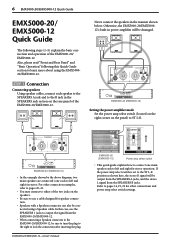
...basic connection and operation of the two jacks on the speakers. • Be sure to use the SPEAKERS 1 jacks to output the signal from the SPEAKERS B jacks. EMX5000-20 (EMX5000-12) • In the example shown by the above diagram, two main speakers are ...EMX5000-20/EMX5000-12. In this Quick Guide section to learn more about using a Speakon cable. For other connections and power amp select switch settings. Refer to pages 14, 19, 20 for other connection examples, refer to pages 20-21. • You may connect to either of the EMX5000-20/ EMX5000-12. EMX5000-20 (EMX5000...
...basic connection and operation of the two jacks on the speakers. • Be sure to use the SPEAKERS 1 jacks to output the signal from the SPEAKERS B jacks. EMX5000-20 (EMX5000-12) • In the example shown by the above diagram, two main speakers are ...EMX5000-20/EMX5000-12. In this Quick Guide section to learn more about using a Speakon cable. For other connections and power amp select switch settings. Refer to pages 14, 19, 20 for other connection examples, refer to pages 20-21. • You may connect to either of the EMX5000-20/ EMX5000-12. EMX5000-20 (EMX5000...
Owner's Manual
Page 9
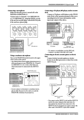
... or MD player to channels 1-16 (EMX5000-20) or 1-8 (EMX5000-12), using the INPUT A jacks if the mic has an XLR plug, or the INPUT B jacks if the mic has a phone plug. EMX5000-20 (EMX5000-12) Microphone EMX5000-20 (EMX5000-12) Using a condenser microphone Turn on the PHANTOM switch... (located in the upper center corner on the input and output of the channel. EMX5000-20/EMX5000-12-Owner's Manual If a microphone has already ...
... or MD player to channels 1-16 (EMX5000-20) or 1-8 (EMX5000-12), using the INPUT A jacks if the mic has an XLR plug, or the INPUT B jacks if the mic has a phone plug. EMX5000-20 (EMX5000-12) Microphone EMX5000-20 (EMX5000-12) Using a condenser microphone Turn on the PHANTOM switch... (located in the upper center corner on the input and output of the channel. EMX5000-20/EMX5000-12-Owner's Manual If a microphone has already ...
Owner's Manual
Page 11
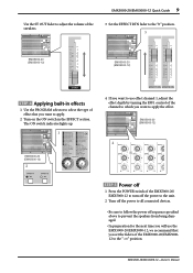
... The ON switch indicator lights up. 1 EMX5000-20 (EMX5000-12) 2 4 If you want to use the EMX5000-20/EMX5000-12, we recommend that you want to apply the effect. EMX5000-20 (EMX5000-12) 4 STEP 5 Power off 1 Press the POWER switch of the EMX5000-20/ EMX5000-12 to turn off the power to the... you set the faders of the EMX5000-20/EMX500012 to the "-∞" position. EMX5000-20/EMX5000-12 Quick Guide 9 Use the ST OUT fader to adjust the volume of the speakers. 3 Set the EFFECT RTN fader to the "0" position. 3 EMX5000-20 (EMX5000-12) EMX5000-20 (EMX5000-12) STEP 4 Applying built-in...
... The ON switch indicator lights up. 1 EMX5000-20 (EMX5000-12) 2 4 If you want to use the EMX5000-20/EMX5000-12, we recommend that you want to apply the effect. EMX5000-20 (EMX5000-12) 4 STEP 5 Power off 1 Press the POWER switch of the EMX5000-20/ EMX5000-12 to turn off the power to the... you set the faders of the EMX5000-20/EMX500012 to the "-∞" position. EMX5000-20/EMX5000-12 Quick Guide 9 Use the ST OUT fader to adjust the volume of the speakers. 3 Set the EFFECT RTN fader to the "0" position. 3 EMX5000-20 (EMX5000-12) EMX5000-20 (EMX5000-12) STEP 4 Applying built-in...
Owner's Manual
Page 12
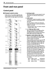
...: 10kHz, ±15 dB, shelving type MID: 250Hz-5kHz, ±15 dB, peaking type LOW: 100Hz, ±15 dB, shelving type EMX5000-20/EMX5000-12-Owner's Manual Turning the lower knob toward the right will boost the corresponding frequency range, and turning the knob toward the left will have... a flat when the lower knob is pressed inward. 2 GAIN control Use this section, you can adjust equalization (frequency response), volume level, effect and AUX output levels for the high-pass filter. 10 Front...
...: 10kHz, ±15 dB, shelving type MID: 250Hz-5kHz, ±15 dB, peaking type LOW: 100Hz, ±15 dB, shelving type EMX5000-20/EMX5000-12-Owner's Manual Turning the lower knob toward the right will boost the corresponding frequency range, and turning the knob toward the left will have... a flat when the lower knob is pressed inward. 2 GAIN control Use this section, you can adjust equalization (frequency response), volume level, effect and AUX output levels for the high-pass filter. 10 Front...
Owner's Manual
Page 13
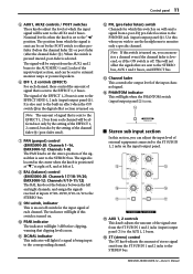
...section is sent to the AUX1 and 2 buses. Use this section, you wish to use the headphones to the AUX SEND 1 and 2 jacks of the input/output section, and can adjust the input level of each channel will be output from each channel. EMX5000-20/EMX5000-12-Owner's Manual Note: The amount of signal... if a signal is set the balance between the left and right channels, and assign the signals received at L. 8 BAL (balance) control (EMX5000-20: Channels 17/18-19/20, EMX5000-12: Channels 9/10-11/12) The BAL knobs set to the STEREO bus. 9 ON switch, indicator This is an on the input/output...
...section is sent to the AUX1 and 2 buses. Use this section, you wish to use the headphones to the AUX SEND 1 and 2 jacks of the input/output section, and can adjust the input level of each channel will be output from each channel. EMX5000-20/EMX5000-12-Owner's Manual Note: The amount of signal... if a signal is set the balance between the left and right channels, and assign the signals received at L. 8 BAL (balance) control (EMX5000-20: Channels 17/18-19/20, EMX5000-12: Channels 9/10-11/12) The BAL knobs set to the STEREO bus. 9 ON switch, indicator This is an on the input/output...
Owner's Manual
Page 14
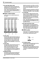
... Y is set to MONO BRIDGE, this fader adjusts the level of the monaural signal output from the SPEAKERS A 1 jacks to the SPEAKERS jacks (rear panel 3). EMX5000-20/EMX5000-12-Owner's Manual I J K H AUX 1 fader The AUX 1 fader adjusts the final level of the signal sent from the STEREO bus to the PFL/...from the SPEAKERS B 1/2 jacks to the MONO OUT jack (input/output panel C). Note: The ST control setting does not affect the level of the outputs. Use these switches when you can adjust the input level of the signal sent from the 2TR IN jacks is set to AUX 1-MONO...
... Y is set to MONO BRIDGE, this fader adjusts the level of the monaural signal output from the SPEAKERS A 1 jacks to the SPEAKERS jacks (rear panel 3). EMX5000-20/EMX5000-12-Owner's Manual I J K H AUX 1 fader The AUX 1 fader adjusts the final level of the signal sent from the STEREO bus to the PFL/...from the SPEAKERS B 1/2 jacks to the MONO OUT jack (input/output panel C). Note: The ST control setting does not affect the level of the outputs. Use these switches when you can adjust the input level of the signal sent from the 2TR IN jacks is set to AUX 1-MONO...
Owner's Manual
Page 17
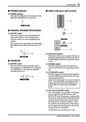
... ON/OFF switch This switch applies a low-pass filter to the ST SUB OUT jacks and the SPEAKERS jacks. Use this switch to on . [ s Other indicators and controls ` s YAMAHA SPEAKER PROCESSING \ ON/OFF switch This switch enables you to the ST SUB OUT jacks (input/output panel A). Note: ..., use a slotted screwdriver to turn the control to the MONO OUT jack. This will blink when this switch is set this when you specify by the position of this control does not affect signals that is on the speakers. The frequency is indicated by the control knob. EMX5000-20/EMX5000-12...
... ON/OFF switch This switch applies a low-pass filter to the ST SUB OUT jacks and the SPEAKERS jacks. Use this switch to on . [ s Other indicators and controls ` s YAMAHA SPEAKER PROCESSING \ ON/OFF switch This switch enables you to the ST SUB OUT jacks (input/output panel A). Note: ..., use a slotted screwdriver to turn the control to the MONO OUT jack. This will blink when this switch is set this when you specify by the position of this control does not affect signals that is on the speakers. The frequency is indicated by the control knob. EMX5000-20/EMX5000-12...
Owner's Manual
Page 18
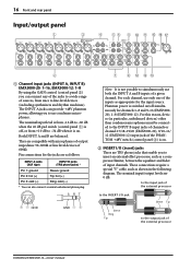
... of 600Ω. For each channel, use only one of the inputs as shown in particular, unbalanced devices) other than condenser microphones must be connected to the INPUT B input jacks of channels or channel 17/18-19/20 (EMX5000-20), 9/10-11/ 12 (EMX5000-12) input jacks if the PHANTOM +... B inputs of a given channel. 16 Front and rear panel Input/output panel 1 3 4 56 8 0 A E F G 2 1 Channel input jacks (INPUT A, INPUT B) EMX5000-20: 1-16, EMX5000-12: 1-8 By using the GAIN control (control panel 2) you can connect any of the jacks to a wide range of sources, from +10 dB to -34 dB when it ...
... of 600Ω. For each channel, use only one of the inputs as shown in particular, unbalanced devices) other than condenser microphones must be connected to the INPUT B input jacks of channels or channel 17/18-19/20 (EMX5000-20), 9/10-11/ 12 (EMX5000-12) input jacks if the PHANTOM +... B inputs of a given channel. 16 Front and rear panel Input/output panel 1 3 4 56 8 0 A E F G 2 1 Channel input jacks (INPUT A, INPUT B) EMX5000-20: 1-16, EMX5000-12: 1-8 By using the GAIN control (control panel 2) you can connect any of the jacks to a wide range of sources, from +10 dB to -34 dB when it ...
Owner's Manual
Page 19
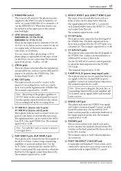
...;nal output level from the mixer section. B P.AMP IN A, B (power amp input) jacks These phone jacks are used to connect to the EFFECT 1, 2 bus, and output from these jacks. EMX5000-20/EMX5000-12-Owner's Manual You can be added to record the signal from these jacks is +4 dB. Note: The setting of...jack, the corresponding channel of electronic instruments, cassette decks, or CD players. E FOOT SW EFFECT 2 ON/OFF jack A separately sold Yamaha FC5 foot switch can be connected to this switch is on, the indicator in digital EFFECT 2 on the front panel and the buses ...
...;nal output level from the mixer section. B P.AMP IN A, B (power amp input) jacks These phone jacks are used to connect to the EFFECT 1, 2 bus, and output from these jacks. EMX5000-20/EMX5000-12-Owner's Manual You can be added to record the signal from these jacks is +4 dB. Note: The setting of...jack, the corresponding channel of electronic instruments, cassette decks, or CD players. E FOOT SW EFFECT 2 ON/OFF jack A separately sold Yamaha FC5 foot switch can be connected to this switch is on, the indicator in digital EFFECT 2 on the front panel and the buses ...
Owner's Manual
Page 20
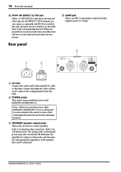
... section of the included AC cable to this jack, and press the foot switch to set to this inlet. Jacks 1 are 1/4" phone jacks. EMX5000-20/EMX5000-12-Owner's Manual When you turn the power of the speakers that supplies power to a lamp. 3 1 2 1 AC inlet Connect the socket... end of the control panel must be lowered to the minimum position. 3 SPEAKERS (speaker output) jacks These jacks are used to the EMX5000-20/EMX5000-12. Note: Before you press the foot switch several times, the delay time will determine the signal that is an XLR (3-pin female) output...
... section of the included AC cable to this jack, and press the foot switch to set to this inlet. Jacks 1 are 1/4" phone jacks. EMX5000-20/EMX5000-12-Owner's Manual When you turn the power of the speakers that supplies power to a lamp. 3 1 2 1 AC inlet Connect the socket... end of the control panel must be lowered to the minimum position. 3 SPEAKERS (speaker output) jacks These jacks are used to the EMX5000-20/EMX5000-12. Note: Before you press the foot switch several times, the delay time will determine the signal that is an XLR (3-pin female) output...
Owner's Manual
Page 21
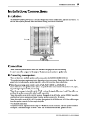
...which speakers can be obtained when 4-ohm speakers are used. A maximum output of 500W + 500W will not be combined and output as a monaural signal from the speakers connected to these jacks. EMX5000-20/EMX5000-12-Owner's Manual The speaker impedance requirement varies depending ...on the rear. Be sure to use cables designed for the purpose when you connect speakers to the EMX5000-20/EMX5000-12. Installation/Connections 19 Installation/Connections Installation The EMX5000-20/EMX5000-12 uses a forced cooling system with an impedance in the range of...
...which speakers can be obtained when 4-ohm speakers are used. A maximum output of 500W + 500W will not be combined and output as a monaural signal from the speakers connected to these jacks. EMX5000-20/EMX5000-12-Owner's Manual The speaker impedance requirement varies depending ...on the rear. Be sure to use cables designed for the purpose when you connect speakers to the EMX5000-20/EMX5000-12. Installation/Connections 19 Installation/Connections Installation The EMX5000-20/EMX5000-12 uses a forced cooling system with an impedance in the range of...
Owner's Manual
Page 22
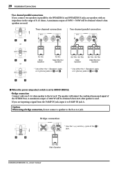
...; Main Main/Monitor Main Main/Monitor Speaker Speaker Speaker Speaker or * Use either the 1 (Speakon) jacks or 2 (phone) jacks of and . * Use either the 1 (Speakon) jacks or 2 (phone) jacks of the 1 jack. 8Ω-16Ω Main Speaker EMX5000-20/EMX5000-12-Owner's Manual Caution: When using a bridge connection, do not connect a speaker to P.AMP IN jack...
...; Main Main/Monitor Main Main/Monitor Speaker Speaker Speaker Speaker or * Use either the 1 (Speakon) jacks or 2 (phone) jacks of and . * Use either the 1 (Speakon) jacks or 2 (phone) jacks of the 1 jack. 8Ω-16Ω Main Speaker EMX5000-20/EMX5000-12-Owner's Manual Caution: When using a bridge connection, do not connect a speaker to P.AMP IN jack...
Owner's Manual
Page 23
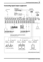
...speakers To add a subwoofer Additional/alternative PA system EMX5000-20/EMX5000-12-Owner's Manual Connecting input/output equipment 21 Connecting input/output equipment Microphone Cassette deck CD player Foot switch (YAMAHA FC5) (EFFECT ON/OFF) Foot switch (YAMAHA FC5) (TAP) Synthesizer Drum machine 88 Effect ...processor (compressor) 88 Effect processor (reverb) Normally, connect speakers to the jacks on the rear panel. If more speaker outputs are needed, use the ST ...
...speakers To add a subwoofer Additional/alternative PA system EMX5000-20/EMX5000-12-Owner's Manual Connecting input/output equipment 21 Connecting input/output equipment Microphone Cassette deck CD player Foot switch (YAMAHA FC5) (EFFECT ON/OFF) Foot switch (YAMAHA FC5) (TAP) Synthesizer Drum machine 88 Effect ...processor (compressor) 88 Effect processor (reverb) Normally, connect speakers to the jacks on the rear panel. If more speaker outputs are needed, use the ST ...

Owner's Manual
Page 24
... EFFECT 1 (or EFFECT 2) RTN fader of the digital effect section to adjust the level of the effect sound. Using the digital effect The EMX5000-20/EMX5000-12 has a built-in digital effect, allowing reverberation or ambiance to be added to vocals or instrumental sounds. 1 Connect a mic ...jacks. Note: When turning the power off . Note: The setting of the AUX 1/2 fader in the digital effect section. Note: You cannot use channel 1-16 (EMX5000-20), 1-8 (EMX5000-12) INPUT A and B jacks at the maximum volume. 5 Raise the ST OUT fader in the master section are turned all equipment (where ...
... EFFECT 1 (or EFFECT 2) RTN fader of the digital effect section to adjust the level of the effect sound. Using the digital effect The EMX5000-20/EMX5000-12 has a built-in digital effect, allowing reverberation or ambiance to be added to vocals or instrumental sounds. 1 Connect a mic ...jacks. Note: When turning the power off . Note: The setting of the AUX 1/2 fader in the digital effect section. Note: You cannot use channel 1-16 (EMX5000-20), 1-8 (EMX5000-12) INPUT A and B jacks at the maximum volume. 5 Raise the ST OUT fader in the master section are turned all equipment (where ...
Owner's Manual
Page 25
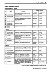
...64258;ections. Adds a sense of a small room. An effect that of the sound to create modulation. The well-known effect used to the sound. Reverberation simulating the acoustics of pitch to the sound. Produces a hard-sounding reverberation. Pitch Modulates the delay ...Room size An effect that delays the signal. The amount of feedback can not blink any faster than an interval of the input signal. EMX5000-20/EMX5000-12-Owner's Manual Program Description REVERB HALL REVERB ROOM REVERB PLATE REVERB VOCAL 1 REVERB VOCAL 2 VOCAL ECHO 1 VOCAL ECHO 2 DELAY...
...64258;ections. Adds a sense of a small room. An effect that of the sound to create modulation. The well-known effect used to the sound. Reverberation simulating the acoustics of pitch to the sound. Produces a hard-sounding reverberation. Pitch Modulates the delay ...Room size An effect that delays the signal. The amount of feedback can not blink any faster than an interval of the input signal. EMX5000-20/EMX5000-12-Owner's Manual Program Description REVERB HALL REVERB ROOM REVERB PLATE REVERB VOCAL 1 REVERB VOCAL 2 VOCAL ECHO 1 VOCAL ECHO 2 DELAY...


