
Owner's Manual
Page 1
.... ENGLISH AX-570/470 Natural Sound Stereo Integrated Amplifier 100W + 100W (8Ω) RMS Output Power, 0.015% THD, 20-20,000 Hz 65W + 65W (8Ω) RMS Output Power, 0.015% THD, 20-20,000 Hz High Dynamic Power, Low Impedance Drive Capability Continuously Variable Loudness Control PURE DIRECT Switch to Reproduce the Purest Source Sound SUBSONIC FILTER Switch to Cut Out Undesirable Ultra-Low-Frequency Signals PRE OUT/MAIN IN Terminals Useful for selecting this YAMAHA stereo integrated amplifier. Model: Serial...
.... ENGLISH AX-570/470 Natural Sound Stereo Integrated Amplifier 100W + 100W (8Ω) RMS Output Power, 0.015% THD, 20-20,000 Hz 65W + 65W (8Ω) RMS Output Power, 0.015% THD, 20-20,000 Hz High Dynamic Power, Low Impedance Drive Capability Continuously Variable Loudness Control PURE DIRECT Switch to Reproduce the Purest Source Sound SUBSONIC FILTER Switch to Cut Out Undesirable Ultra-Low-Frequency Signals PRE OUT/MAIN IN Terminals Useful for selecting this YAMAHA stereo integrated amplifier. Model: Serial...
Owner's Manual
Page 2
... the operating instructions. Use a clean, dry cloth. 2 7 Always set the volume control to "- ∞" before starting the audio source play: increase the volume gradually to an appropriate level after the play is started. 8 To prevent lightning damage, pull out the power cord and remove the antenna cable during an electrical storm. 9 When not planning to use force on common operating errors before concluding that your unit in the operating instructions or...
... the operating instructions. Use a clean, dry cloth. 2 7 Always set the volume control to "- ∞" before starting the audio source play: increase the volume gradually to an appropriate level after the play is started. 8 To prevent lightning damage, pull out the power cord and remove the antenna cable during an electrical storm. 9 When not planning to use force on common operating errors before concluding that your unit in the operating instructions or...
Owner's Manual
Page 3
... product has been tested and found in FCC Regulations, Part 15 for Class "B" digital devices. In the case of the following parts are on different branch (circuit breaker or fuse) circuits or install AC line filter/s. PRESET + A/B/C/D/E TUNER DIR A DECK A/B DIR B TAPE 1 PLAY TAPE 2 REC/PAUSE STOP REC MUTE PRESET SKIP ON/FLAT EQ AUX - + VOLUME 3 Cable/s supplied with the requirements listed in the users manual, may void...
... product has been tested and found in FCC Regulations, Part 15 for Class "B" digital devices. In the case of the following parts are on different branch (circuit breaker or fuse) circuits or install AC line filter/s. PRESET + A/B/C/D/E TUNER DIR A DECK A/B DIR B TAPE 1 PLAY TAPE 2 REC/PAUSE STOP REC MUTE PRESET SKIP ON/FLAT EQ AUX - + VOLUME 3 Cable/s supplied with the requirements listed in the users manual, may void...
Owner's Manual
Page 4
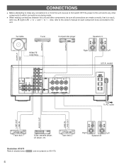
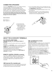
... outlet LINE OUT LINE IN AUDIO OUT LINE IN LINE OUT Tape deck 1 Video cassette player, LD player, etc. Tape deck 2 Illustration: AX-570 Parts in shaded area ( ) are not present on AX-470. 4 Right Left Speakers B Also, refer to the owner's manual for each component to be sure all connections are made . OUTPUT GND OUTPUT OUTPUT Turntable Tuner REMOTE CONTROL Compact disc player Speakers A Right Left (U.S.A. CONNECTIONS q Before attempting to make any connections to or from this unit...
... outlet LINE OUT LINE IN AUDIO OUT LINE IN LINE OUT Tape deck 1 Video cassette player, LD player, etc. Tape deck 2 Illustration: AX-570 Parts in shaded area ( ) are not present on AX-470. 4 Right Left Speakers B Also, refer to the owner's manual for each component to be sure all connections are made . OUTPUT GND OUTPUT OUTPUT Turntable Tuner REMOTE CONTROL Compact disc player Speakers A Right Left (U.S.A. CONNECTIONS q Before attempting to make any connections to or from this unit...
Owner's Manual
Page 5
... terminal will be connected to the SWITCHED AC OUTLETS is 100 watts. Do not let the bare speaker wires touch each other component is controlled by using the cable provided with wire of a control amplifier and a power amplifier. REMOTE CONTROL (PHONO) connector If you connect only one speaker system, connect it to this connector by this unit can be heard from the PRE OUT/MAIN IN terminals, connect the inputs of that unit...
... terminal will be connected to the SWITCHED AC OUTLETS is 100 watts. Do not let the bare speaker wires touch each other component is controlled by using the cable provided with wire of a control amplifier and a power amplifier. REMOTE CONTROL (PHONO) connector If you connect only one speaker system, connect it to this connector by this unit can be heard from the PRE OUT/MAIN IN terminals, connect the inputs of that unit...
Owner's Manual
Page 6
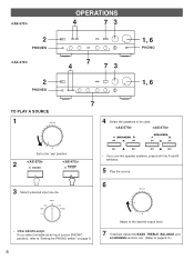
2 PHONES 2 PHONES TO PLAY A SOURCE 1 OPERATIONS 4 73 4 7 73 1, 6 PHONO 1, 6 7 4 Select the speakers to page 8-9.) SPEAKERS SPEAKERS ∞ Set to the " " position. 2 POWER POWER /STANDBY 3 Select a desired input source. * If you use two speaker systems, press both the A and B switches. 5 Play the source. 6 * If you select turntable as an input source (PHONO position), refer to "Setting the PHONO switch" on page 9. 6 Adjust to the desired output level. 7 If desired, adjust the BASS, TREBLE, BALANCE and LOUDNESS controls, etc. (Refer to be used.
2 PHONES 2 PHONES TO PLAY A SOURCE 1 OPERATIONS 4 73 4 7 73 1, 6 PHONO 1, 6 7 4 Select the speakers to page 8-9.) SPEAKERS SPEAKERS ∞ Set to the " " position. 2 POWER POWER /STANDBY 3 Select a desired input source. * If you use two speaker systems, press both the A and B switches. 5 Play the source. 6 * If you select turntable as an input source (PHONO position), refer to "Setting the PHONO switch" on page 9. 6 Adjust to the desired output level. 7 If desired, adjust the BASS, TREBLE, BALANCE and LOUDNESS controls, etc. (Refer to be used.
Owner's Manual
Page 7
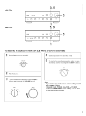
... TAPE 1 TUNER TAPE 2 PHONO AUX 5 To monitor the sound being recorded, select the tape deck being recorded. 7 ENGLISH 3, 5 3 1 3, 5 3 1 TO RECORD A SOURCE TO TAPE (OR DUB FROM A TAPE TO ANOTHER) 1 Select the source to enjoy another source while recording, select it with the INPUT selector. q VOLUME, BASS, TREBLE, BALANCE, LOUDNESS controls and PURE DIRECT switch settings have no effect on the material being used for recording with the INPUT selecto. 2 Play the source. 3 Confirm the source by selecting it with the INPUT selector and turning...
... TAPE 1 TUNER TAPE 2 PHONO AUX 5 To monitor the sound being recorded, select the tape deck being recorded. 7 ENGLISH 3, 5 3 1 3, 5 3 1 TO RECORD A SOURCE TO TAPE (OR DUB FROM A TAPE TO ANOTHER) 1 Select the source to enjoy another source while recording, select it with the INPUT selector. q VOLUME, BASS, TREBLE, BALANCE, LOUDNESS controls and PURE DIRECT switch settings have no effect on the material being used for recording with the INPUT selecto. 2 Play the source. 3 Confirm the source by selecting it with the INPUT selector and turning...
Owner's Manual
Page 8
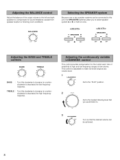
... TREBLE controls BASS l 0l 2 2 3 3 4 5 4 5 TREBLE l 0l 2 2 3 3 4 5 4 5 BASS : Turn this clockwise to increase (or counterclockwise to decrease) the high frequency response. BALANCE l 0l 2 2 3 3 4 L5 4 5R Selecting the SPEAKER system Because one or two speaker systems can be connected to this clockwise to increase (or counterclockwise to decrease) the low frequency response. TREBLE : Turn this unit, the SPEAKERS switches allow you to compensate for the human ears' loss of the output volume...
... TREBLE controls BASS l 0l 2 2 3 3 4 5 4 5 TREBLE l 0l 2 2 3 3 4 5 4 5 BASS : Turn this clockwise to increase (or counterclockwise to decrease) the high frequency response. BALANCE l 0l 2 2 3 3 4 L5 4 5R Selecting the SPEAKER system Because one or two speaker systems can be connected to this clockwise to increase (or counterclockwise to decrease) the low frequency response. TREBLE : Turn this unit, the SPEAKERS switches allow you to compensate for the human ears' loss of the output volume...
Owner's Manual
Page 9
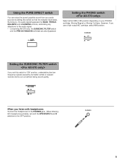
... possible sound from your PHONO cartridge, Moving Magnet or Moving Coil type. PHONO MC MM Setting the SUBSONIC FILTER switch If you use a high output MC cartridge, select MM position. When listening with headphones Connect the headphones to the audio signal. * Concerning AX-570 only, the SUBSONIC FILTER switch and the PRE OUT/MAIN IN terminals are also bypassed. By doing so, the audio signal bypasses the BASS, TREBLE, BALANCE...
... possible sound from your PHONO cartridge, Moving Magnet or Moving Coil type. PHONO MC MM Setting the SUBSONIC FILTER switch If you use a high output MC cartridge, select MM position. When listening with headphones Connect the headphones to the audio signal. * Concerning AX-570 only, the SUBSONIC FILTER switch and the PRE OUT/MAIN IN terminals are also bypassed. By doing so, the audio signal bypasses the BASS, TREBLE, BALANCE...
Owner's Manual
Page 10
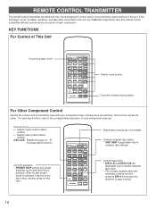
... AUX - + VOLUME Selects input source. If these keys are identical, their function will also control various functions of the unit. REMOTE CONTROL TRANSMITTER The remote control transmitter provided with this key.) PLAY/CUT PHONO POWER SKIP PLAY CD SEARCH PAUSE/STOP DISC SKIP - KEY FUNCTIONS For Control of preset station buttons. For Other Component Control Identify the remote control transmitter keys with automatic reverse function, pressing DIR A will reverse the direction of tape running. 10 Controls compact disc player. * DISC SKIP is designed to control...
... AUX - + VOLUME Selects input source. If these keys are identical, their function will also control various functions of the unit. REMOTE CONTROL TRANSMITTER The remote control transmitter provided with this key.) PLAY/CUT PHONO POWER SKIP PLAY CD SEARCH PAUSE/STOP DISC SKIP - KEY FUNCTIONS For Control of preset station buttons. For Other Component Control Identify the remote control transmitter keys with automatic reverse function, pressing DIR A will reverse the direction of tape running. 10 Controls compact disc player. * DISC SKIP is designed to control...
Owner's Manual
Page 11
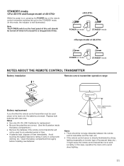
q If the remote control sensor is half illuminated.) Note The POWER switch on mode STANDBY mode NOTES ABOUT THE REMOTE CONTROL TRANSMITTER Battery installation Remote control transmitter operation range 1 3 Remote control 2 sensor Battery replacement If you find that the remote control transmitter must be used for an extended period of them immediately. In this case, reposition the main unit to avoid direct lighting. 11 POWER on mode STANDBY mode POWER on the front panel of this unit should be...
q If the remote control sensor is half illuminated.) Note The POWER switch on mode STANDBY mode NOTES ABOUT THE REMOTE CONTROL TRANSMITTER Battery installation Remote control transmitter operation range 1 3 Remote control 2 sensor Battery replacement If you find that the remote control transmitter must be used for an extended period of them immediately. In this case, reposition the main unit to avoid direct lighting. 11 POWER on mode STANDBY mode POWER on the front panel of this unit should be...
Owner's Manual
Page 12
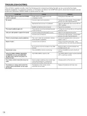
... inserted. Connect the speaker wires in the power cord. Firmly connect the audio plugs. The LOUDNESS control is ON. The PURE DIRECT switch is functioning. If it to the appropriate position. Incorrect setting of the main unit. Connect the cords properly. Sound level is not selected. Using the BASS, TREBLE, BALANCE, LOUDNESS controls and SUBSONIC FILTER switch (AX-570 only) does not affect the tone. Change position of the BALANCE control. Sound "hums". Incorrect cord connections. Select an appropriate input source with new ones. 12 Replace the...
... inserted. Connect the speaker wires in the power cord. Firmly connect the audio plugs. The LOUDNESS control is ON. The PURE DIRECT switch is functioning. If it to the appropriate position. Incorrect setting of the main unit. Connect the cords properly. Sound level is not selected. Using the BASS, TREBLE, BALANCE, LOUDNESS controls and SUBSONIC FILTER switch (AX-570 only) does not affect the tone. Change position of the BALANCE control. Sound "hums". Incorrect cord connections. Select an appropriate input source with new ones. 12 Replace the...
Owner's Manual
Page 13
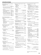
...% THD [U.S.A. and General model 70W+70W [Europe (except Scandinavia) model 80W+80W Dynamic Power per Channel (by IHF Dynamic Headroom measuring method) 8/6/4/2 ohms 140/170/220/290W [Except Europe model] 8/6/4/2 ohms 95/115/135/160W [Europe model] 8/6/4/2 ohms 115/135/160/180W DIN Standard Output Power per Channel (PURE DIRECT; SPECIFICATIONS ENGLISH Minimum RMS Output Power per Channel (4 ohms, 1 kHz, 0.7% THD) [Europe model only] and Canada model] .......75W+75W [Australia...
...% THD [U.S.A. and General model 70W+70W [Europe (except Scandinavia) model 80W+80W Dynamic Power per Channel (by IHF Dynamic Headroom measuring method) 8/6/4/2 ohms 140/170/220/290W [Except Europe model] 8/6/4/2 ohms 95/115/135/160W [Europe model] 8/6/4/2 ohms 115/135/160/180W DIN Standard Output Power per Channel (PURE DIRECT; SPECIFICATIONS ENGLISH Minimum RMS Output Power per Channel (4 ohms, 1 kHz, 0.7% THD) [Europe model only] and Canada model] .......75W+75W [Australia...


