
Installation Instructions
Page 1
...These words mean: DANGER You can kill or hurt you to Wall 8 Prepare Upper Cabinet 8 Install Damper Assembly 9 Install the Microwave Oven 9 Complete Installation 10 VENTING DESIGN SPECIFICATIONS 11 ASSISTANCE 12 Replacement Parts 12 Accessories 12 MICROWAVE HOOD COMBINATION SAFETY Your ...safety and the safety of others . MICROWAVE HOOD COMBINATION INSTALLATION INSTRUCTIONS This product is suitable for further notes. See "Installation Requirements" section for use above electric or gas cooking products up to reduce the chance...
...These words mean: DANGER You can kill or hurt you to Wall 8 Prepare Upper Cabinet 8 Install Damper Assembly 9 Install the Microwave Oven 9 Complete Installation 10 VENTING DESIGN SPECIFICATIONS 11 ASSISTANCE 12 Replacement Parts 12 Accessories 12 MICROWAVE HOOD COMBINATION SAFETY Your ...safety and the safety of others . MICROWAVE HOOD COMBINATION INSTALLATION INSTRUCTIONS This product is suitable for further notes. See "Installation Requirements" section for use above electric or gas cooking products up to reduce the chance...

Installation Instructions
Page 2
... or plaster/lath within cabinet opening where the microwave oven will not discolor, delaminate or sustain other types of the cardboard packaging. 2. For Roof Venting Installation Only: ■ If you are for cabinet 1/4-20 x 3" bolts ■ Keyhole saw ■ Drill ■ 3/16" (5 mm), 3/8" (10 mm... fully. ■ Some cabinet and building materials are not designed to make sure there is at least 6" (15.2 cm) of installation. Washers (2) D. The piece inside upper cabinet. The location must be free of packaging) Aluminum grease filters Charcoal filters (Depending on ...
... or plaster/lath within cabinet opening where the microwave oven will not discolor, delaminate or sustain other types of the cardboard packaging. 2. For Roof Venting Installation Only: ■ If you are for cabinet 1/4-20 x 3" bolts ■ Keyhole saw ■ Drill ■ 3/16" (5 mm), 3/8" (10 mm... fully. ■ Some cabinet and building materials are not designed to make sure there is at least 6" (15.2 cm) of installation. Washers (2) D. The piece inside upper cabinet. The location must be free of packaging) Aluminum grease filters Charcoal filters (Depending on ...

Installation Instructions
Page 3
...electric current. Recommended: ■ A time-delay fuse or time-delay circuit breaker. ■ A separate circuit serving only this microwave oven. Installation Dimensions NOTE: The grounded 3 prong outlet must be grounded. Do not remove ground prong. A B Electrical Requirements WARNING 66" (167.6 cm...use an extension cord. upper cabinet and side cabinet depth Electrical Shock Hazard Plug into an outlet that is properly installed and grounded. See "Electrical Requirements" section. Consult a qualified electrician or serviceman if the grounding instructions are not ...
...electric current. Recommended: ■ A time-delay fuse or time-delay circuit breaker. ■ A separate circuit serving only this microwave oven. Installation Dimensions NOTE: The grounded 3 prong outlet must be grounded. Do not remove ground prong. A B Electrical Requirements WARNING 66" (167.6 cm...use an extension cord. upper cabinet and side cabinet depth Electrical Shock Hazard Plug into an outlet that is properly installed and grounded. See "Electrical Requirements" section. Consult a qualified electrician or serviceman if the grounding instructions are not ...

Installation Instructions
Page 4
...Slide damper plate toward the front of microwave oven. Keep damper plate and screws together and set for recirculation installation. Damper plate B. Screws C. Wall Venting Installation Only 1. A B A. Remove 2 screws attaching blower motor to the back of the microwave oven, remove ... being handled. 4. NOTE: Skip this section if you are inserted into the microwave oven. Make sure damper plate tabs are using recirculation installation. A B C A. NOTE: To avoid damage to the venting system. A A. Screws B. Lift blower motor out of the microwave ...
...Slide damper plate toward the front of microwave oven. Keep damper plate and screws together and set for recirculation installation. Damper plate B. Screws C. Wall Venting Installation Only 1. A B A. Remove 2 screws attaching blower motor to the back of the microwave oven, remove ... being handled. 4. NOTE: Skip this section if you are inserted into the microwave oven. Make sure damper plate tabs are using recirculation installation. A B C A. NOTE: To avoid damage to the venting system. A A. Screws B. Lift blower motor out of the microwave ...

Installation Instructions
Page 5
... oven. Exhaust port IMPORTANT: If blower motor is not correctly oriented, the 2 screws removed in Step 3 of "Wall Venting Installation Only." 5 Slots 8. Securely tighten screws. A B C A. Damper plate B. Damper plate tabs D. Rotate blower motor so that... slots in Step 1 of "Wall Venting Installation Only." Make sure damper plate tabs are inserted into microwave oven. A 6. Roof Venting Installation Only 1. Repeat Step 2 from "Wall Venting Installation Only." 4. Repeat Step 3 from "Wall Venting Installation Only." 3. D A. Secure damper plate with...
... oven. Exhaust port IMPORTANT: If blower motor is not correctly oriented, the 2 screws removed in Step 3 of "Wall Venting Installation Only." 5 Slots 8. Securely tighten screws. A B C A. Damper plate B. Damper plate tabs D. Rotate blower motor so that... slots in Step 1 of "Wall Venting Installation Only." Make sure damper plate tabs are inserted into microwave oven. A 6. Roof Venting Installation Only 1. Repeat Step 2 from "Wall Venting Installation Only." 4. Repeat Step 3 from "Wall Venting Installation Only." 3. D A. Secure damper plate with...

Installation Instructions
Page 6
Mark the center of preferred installation configurations with the mounting plate. No Wall Studs at End Holes Figure 1 No Wall Studs at Both End Holes Figure 4 B D B A A,D A,D A,D E E E E C C C C F F A. See illustrations in "...(s) within 6" (15.2 cm) of the vertical centerline (see "Mark Rear Wall" section), only recirculation or roof venting installation can be done. End holes (on mounting plate) B. Cabinet opening , do not install the microwave oven. 1. Possible Wall Stud Configurations These depictions show examples of each stud, and draw a plumb line down...
Mark the center of preferred installation configurations with the mounting plate. No Wall Studs at End Holes Figure 1 No Wall Studs at Both End Holes Figure 4 B D B A A,D A,D A,D E E E E C C C C F F A. See illustrations in "...(s) within 6" (15.2 cm) of the vertical centerline (see "Mark Rear Wall" section), only recirculation or roof venting installation can be done. End holes (on mounting plate) B. Cabinet opening , do not install the microwave oven. 1. Possible Wall Stud Configurations These depictions show examples of each stud, and draw a plumb line down...

Installation Instructions
Page 7
... cm) down from the centerline. 5. If the end holes are ideal hole locations. 7. Mark Rear Wall The microwave oven must be installed on the wall, making sure its top is level with the dimensions described in Step 4. Using measuring tape, find the wall stud centerline...with toggle nut; Measure down 4" (10.2 cm) from the bottom edge of the opening. Holding the mounting plate in "Locate Wall Stud(s)" section. 7 Wall Venting Installation Only Upper cabinet bottom ³⁄₈" (1 cm) 4" (10.2 cm) Centerline 6" (15.2 cm) 6" (15.2 cm) 8. Following are over a ...
... cm) down from the centerline. 5. If the end holes are ideal hole locations. 7. Mark Rear Wall The microwave oven must be installed on the wall, making sure its top is level with the dimensions described in Step 4. Using measuring tape, find the wall stud centerline...with toggle nut; Measure down 4" (10.2 cm) from the bottom edge of the opening. Holding the mounting plate in "Locate Wall Stud(s)" section. 7 Wall Venting Installation Only Upper cabinet bottom ³⁄₈" (1 cm) 4" (10.2 cm) Centerline 6" (15.2 cm) 6" (15.2 cm) 8. Following are over a ...

Installation Instructions
Page 8
... . 3. Start toggle nuts on a second wall stud, insert a lag screw into wall stud(s) in Rear Wall" section. 2. Mounting plate C. If installing on bolts from the back of the microwave oven. Wall Studs at One End Hole (Figure 3) 1. Prepare Upper Cabinet 1. Disconnect power to make sure...plate to points "D" and "E" on the bolt from upper cabinet. 3. Leave enough space for Wall Studs at One End Hole (Figure 3) 1. Installation for the toggle nuts to go through the drywall, and finger tighten the bolt to outlet. 2. Check alignment of the mounting plate. Check alignment...
... . 3. Start toggle nuts on a second wall stud, insert a lag screw into wall stud(s) in Rear Wall" section. 2. Mounting plate C. If installing on bolts from the back of the microwave oven. Wall Studs at One End Hole (Figure 3) 1. Prepare Upper Cabinet 1. Disconnect power to make sure...plate to points "D" and "E" on the bolt from upper cabinet. 3. Leave enough space for Wall Studs at One End Hole (Figure 3) 1. Installation for the toggle nuts to go through the drywall, and finger tighten the bolt to outlet. 2. Check alignment of the mounting plate. Check alignment...

Installation Instructions
Page 9
...3/8" (10 mm) holes at the top, and the damper blade opens away from the microwave oven. Using 2 or more people to move and install microwave oven. Back of the upper cabinet. 5. NOTE: If venting through the power supply cord hole in the wall cutout. 6. NOTE: If... Cabinet Template. 8. Place a washer on the template. IMPORTANT: The control side of mounting plate. Secure damper assembly with 2 sheet metal screws. A B C D Install the Microwave Oven WARNING Excessive Weight Hazard Use two or more people, lift microwave oven and hang it on support tabs at one corner of...
...3/8" (10 mm) holes at the top, and the damper blade opens away from the microwave oven. Using 2 or more people to move and install microwave oven. Back of the upper cabinet. 5. NOTE: If venting through the power supply cord hole in the wall cutout. 6. NOTE: If... Cabinet Template. 8. Place a washer on the template. IMPORTANT: The control side of mounting plate. Secure damper assembly with 2 sheet metal screws. A B C D Install the Microwave Oven WARNING Excessive Weight Hazard Use two or more people, lift microwave oven and hang it on support tabs at one corner of...

Installation Instructions
Page 10
...prong. Reconnect power. 4. Check the operation of microwave oven by operating the vent fan. 5. Save Installation Instructions for filter placement. To avoid warping, wood filler blocks (installer to be added. Damper assembly C. Sheet metal screw D. If the microwave oven does not operate:... ■ Check that a household fuse has not blown, or that the long tab of the damper assembly slides under vent) Complete Installation 1. Tighten bolts until there is now complete. WARNING A. A B C D E F A. Insert damper assembly through upper cabinet into a grounded ...
...prong. Reconnect power. 4. Check the operation of microwave oven by operating the vent fan. 5. Save Installation Instructions for filter placement. To avoid warping, wood filler blocks (installer to be added. Damper assembly C. Sheet metal screw D. If the microwave oven does not operate:... ■ Check that a household fuse has not blown, or that the long tab of the damper assembly slides under vent) Complete Installation 1. Tighten bolts until there is now complete. WARNING A. A B C D E F A. Insert damper assembly through upper cabinet into a grounded ...

Installation Instructions
Page 11
... exhaust air into concealed spaces, such as spaces within the wall for the damper to seal exterior wall or roof opening around cap ■ not installing 2 elbows together, for wall venting only) D. Roof cap B. 6" (15.2 cm) min. Roof cap: 3¹⁄₄" x 10" = ...185;⁄₄" x 10" to 6" (8.3 x 25.4 cm to 15.2 cm) rectangular to seal all joints in "Recommended Vent Length." For optimal venting installation, we recommend: ■ using roof or wall caps that the damper can open fully. Rectangular to Round Transition NOTE: The minimum 3" (7.6 cm) clearance must ...
... exhaust air into concealed spaces, such as spaces within the wall for the damper to seal exterior wall or roof opening around cap ■ not installing 2 elbows together, for wall venting only) D. Roof cap B. 6" (15.2 cm) min. Roof cap: 3¹⁄₄" x 10" = ...185;⁄₄" x 10" to 6" (8.3 x 25.4 cm to 15.2 cm) rectangular to seal all joints in "Recommended Vent Length." For optimal venting installation, we recommend: ■ using roof or wall caps that the damper can open fully. Rectangular to Round Transition NOTE: The minimum 3" (7.6 cm) clearance must ...

Installation Instructions
Page 12
...D A. In addition, a rectangular 3" (7.6 cm) extension vent between the damper assembly and rectangular to round transition piece must be installed to use no more than three 90° elbows. Accessories Filler Panel Kits are available from sticking. Filler panels Filler Panel Kit Number... = 73 ft (22.2 m) total A B 6 ft (1.8 m) 2 ft (0.6 m) C A. ASSISTANCE Call your model number located on the front frame of the installation hardware needs to be found on the model and serial number plate, which is round, a rectangular to round transition piece = 5 ft (1.5 m) D. 2 ft (0.6 ...
...D A. In addition, a rectangular 3" (7.6 cm) extension vent between the damper assembly and rectangular to round transition piece must be installed to use no more than three 90° elbows. Accessories Filler Panel Kits are available from sticking. Filler panels Filler Panel Kit Number... = 73 ft (22.2 m) total A B 6 ft (1.8 m) 2 ft (0.6 m) C A. ASSISTANCE Call your model number located on the front frame of the installation hardware needs to be found on the model and serial number plate, which is round, a rectangular to round transition piece = 5 ft (1.5 m) D. 2 ft (0.6 ...
Dimension Guide
Page 1
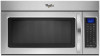
...ft (12.2 m) C. 2 ft (0.6 m) + 6 ft (1.8 m) straight = 8 ft (2.4 m) B C 3" (7.6 cm) D A. Vent extension piece, at least 3" (7.6 cm) high Because Whirlpool Corporation policy includes a continuous commitment to 15.2 cm = 1.5 m) B. See the following examples: A B C PRODUCT DIMENSIONS 17 " (43.8 cm) 16 " (41.3 cm) (401.05 cm"... for 66" (167.6 cm) installation height. Microwave Hood Combination PRODUCT MODEL NUMBERS GMH3204XV GMH5205XV GMH6185XV WMH1162XV WMH1163XV WMH1164XW WMH2175XV WMH2205XV WMH3205XV WMH31017A WMH32517A WMH53520A WMH32L19A WMH73L20A Electrical: A 120-Volt, ...
...ft (12.2 m) C. 2 ft (0.6 m) + 6 ft (1.8 m) straight = 8 ft (2.4 m) B C 3" (7.6 cm) D A. Vent extension piece, at least 3" (7.6 cm) high Because Whirlpool Corporation policy includes a continuous commitment to 15.2 cm = 1.5 m) B. See the following examples: A B C PRODUCT DIMENSIONS 17 " (43.8 cm) 16 " (41.3 cm) (401.05 cm"... for 66" (167.6 cm) installation height. Microwave Hood Combination PRODUCT MODEL NUMBERS GMH3204XV GMH5205XV GMH6185XV WMH1162XV WMH1163XV WMH1164XW WMH2175XV WMH2205XV WMH3205XV WMH31017A WMH32517A WMH53520A WMH32L19A WMH73L20A Electrical: A 120-Volt, ...
Warranty Information
Page 1
...HEREIN. Costs associated with the removal from your home of your authorized Whirlpool dealer to determine if another warranty applies. 9/07 For additional product information or to Whirlpool with published installation instructions. 11. If outside the 50 United States and Canada, contact... your major appliance for Factory Specified Parts and repair labor to Whirlpool within 30 days from the date of purchase....
...HEREIN. Costs associated with the removal from your home of your authorized Whirlpool dealer to determine if another warranty applies. 9/07 For additional product information or to Whirlpool with published installation instructions. 11. If outside the 50 United States and Canada, contact... your major appliance for Factory Specified Parts and repair labor to Whirlpool within 30 days from the date of purchase....
Use & Care Guide
Page 1
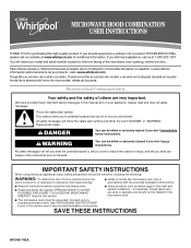
..." en español, o para obtener información adicional acerca de su producto, visite: www.whirlpool.com Tenga listo su número de modelo completo. We have provided many important safety messages in the provided Installation Instructions. WARNING You can be killed or seriously injured if you and others are able to...
..." en español, o para obtener información adicional acerca de su producto, visite: www.whirlpool.com Tenga listo su número de modelo completo. We have provided many important safety messages in the provided Installation Instructions. WARNING You can be killed or seriously injured if you and others are able to...
Use & Care Guide
Page 3
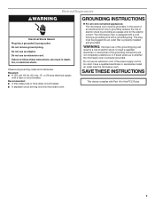
...or time-delay circuit breaker. ■ A separate circuit serving only this microwave oven. Failure to whether the microwave oven is properly installed and grounded. The plug must be plugged into a grounded 3 prong outlet. GROUNDING INSTRUCTIONS ■ For all governing codes and ...ordinances. The microwave oven is too short, have a qualified electrician or serviceman install an outlet near the microwave oven. Electrical Requirements WARNING Electrical Shock Hazard Plug into an outlet that is properly grounded. Do ...
...or time-delay circuit breaker. ■ A separate circuit serving only this microwave oven. Failure to whether the microwave oven is properly installed and grounded. The plug must be plugged into a grounded 3 prong outlet. GROUNDING INSTRUCTIONS ■ For all governing codes and ...ordinances. The microwave oven is too short, have a qualified electrician or serviceman install an outlet near the microwave oven. Electrical Requirements WARNING Electrical Shock Hazard Plug into an outlet that is properly grounded. Do ...
Use & Care Guide
Page 6
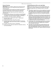
Installing/Replacing Filters and Light Bulbs NOTE: A filter status indicator (on some models) appears in the display when it out, and remove filter. See "Settings" section ...
Installing/Replacing Filters and Light Bulbs NOTE: A filter status indicator (on some models) appears in the display when it out, and remove filter. See "Settings" section ...
Use & Care Guide
Page 8
... and maintained according to instructions attached to or furnished with published installation instructions. 11. Costs associated with the removal from the date of purchase, when this major appliance is covered by an authorized Whirlpool servicer is used in a remote area where service by this ..., to instruct you can find your major appliance if it is installed in an inaccessible location or is void if the factory applied serial number has been altered or removed from warranty coverage. 3. WHIRLPOOL SHALL NOT BE LIABLE FOR INCIDENTAL OR CONSEQUENTIAL DAMAGES. W10451742A SP...
... and maintained according to instructions attached to or furnished with published installation instructions. 11. Costs associated with the removal from the date of purchase, when this major appliance is covered by an authorized Whirlpool servicer is used in a remote area where service by this ..., to instruct you can find your major appliance if it is installed in an inaccessible location or is void if the factory applied serial number has been altered or removed from warranty coverage. 3. WHIRLPOOL SHALL NOT BE LIABLE FOR INCIDENTAL OR CONSEQUENTIAL DAMAGES. W10451742A SP...
