
Installation Instructions
Page 1
... HOOD COMBINATION SAFETY Your safety and the safety of Contents MICROWAVE HOOD COMBINATION SAFETY 1 INSTALLATION REQUIREMENTS 2 Tools and Parts 2 Remove Cardboard Template 2 Location Requirements 2 Product Dimensions 3 Electrical Requirements 3 INSTALLATION INSTRUCTIONS 4 Remove Mounting Plate 4 Rotate Blower Motor 4 Locate Wall Stud(s 6 Mark Rear Wall 7 Drill Holes in these installation instructions. All safety messages...
... HOOD COMBINATION SAFETY Your safety and the safety of Contents MICROWAVE HOOD COMBINATION SAFETY 1 INSTALLATION REQUIREMENTS 2 Tools and Parts 2 Remove Cardboard Template 2 Location Requirements 2 Product Dimensions 3 Electrical Requirements 3 INSTALLATION INSTRUCTIONS 4 Remove Mounting Plate 4 Rotate Blower Motor 4 Locate Wall Stud(s 6 Mark Rear Wall 7 Drill Holes in these installation instructions. All safety messages...

Installation Instructions
Page 2
.... The piece inside upper cabinet. The location must be sure to back of microwave oven) Cardboard template (part of installation. See "Installation Dimensions" illustration. ■ Minimum one 2" x 4" (50.8 x 101.6 mm) wood wall stud and minimum 3/8" (10 mm) thickness ..., see "Replacement Parts" section. Special Requirements For Wall Venting Installation Only: ■ Cutout must provide: ■ Minimum installation dimensions. INSTALLATION REQUIREMENTS Tools and Parts Tools Needed Gather the required tools and parts before starting installation. hole drill ■ No. 2...
.... The piece inside upper cabinet. The location must be sure to back of microwave oven) Cardboard template (part of installation. See "Installation Dimensions" illustration. ■ Minimum one 2" x 4" (50.8 x 101.6 mm) wood wall stud and minimum 3/8" (10 mm) thickness ..., see "Replacement Parts" section. Special Requirements For Wall Venting Installation Only: ■ Cutout must provide: ■ Minimum installation dimensions. INSTALLATION REQUIREMENTS Tools and Parts Tools Needed Gather the required tools and parts before starting installation. hole drill ■ No. 2...

Installation Instructions
Page 3
... electric current. Failure to whether the microwave oven is properly grounded. or 20-amp electrical supply with a grounding plug. Exact dimensions may vary depending on type of electric shock. In the event of an electrical short circuit, grounding reduces the risk of electric...not remove ground prong. Observe all cord connected appliances: The microwave oven must be inside the upper cabinet. Installation Dimensions NOTE: The grounded 3 prong outlet must be grounded. Product Dimensions 17¹⁄₄" (43.8 cm) 16¹⁄₄" (41.3 cm) (401.05³c⁄...
... electric current. Failure to whether the microwave oven is properly grounded. or 20-amp electrical supply with a grounding plug. Exact dimensions may vary depending on type of electric shock. In the event of an electrical short circuit, grounding reduces the risk of electric...not remove ground prong. Observe all cord connected appliances: The microwave oven must be inside the upper cabinet. Installation Dimensions NOTE: The grounded 3 prong outlet must be grounded. Product Dimensions 17¹⁄₄" (43.8 cm) 16¹⁄₄" (41.3 cm) (401.05³c⁄...

Installation Instructions
Page 7
... Wall Studs at the hole(s) marked in Step 8, and mark. 11. Cardboard template C. D. Cut a 3/4" (19 mm) hole in one 1/4-20 x 3" round-head bolt with the dimensions described in steps 8 and 10. 12. Drill 3/16" (5 mm) hole(s) into the wall stud(s) at End Holes (Figures 1 & 2) 1. Wall Venting Installation Only Upper cabinet bottom...
... Wall Studs at the hole(s) marked in Step 8, and mark. 11. Cardboard template C. D. Cut a 3/4" (19 mm) hole in one 1/4-20 x 3" round-head bolt with the dimensions described in steps 8 and 10. 12. Drill 3/16" (5 mm) hole(s) into the wall stud(s) at End Holes (Figures 1 & 2) 1. Wall Venting Installation Only Upper cabinet bottom...

Installation Instructions
Page 8
... of "Installation for No Wall Studs at One End Hole (Figure 3) 1. Mounting plate C. Place Upper Cabinet Template against drywall. 5. Make sure the 10" (25.4 cm) dimension from the back of mounting plate. 2. Mounting plate C. Attach Mounting Plate to Wall NOTE: Secure the mounting plate to make sure toggle nut has opened...
... of "Installation for No Wall Studs at One End Hole (Figure 3) 1. Mounting plate C. Place Upper Cabinet Template against drywall. 5. Make sure the 10" (25.4 cm) dimension from the back of mounting plate. 2. Mounting plate C. Attach Mounting Plate to Wall NOTE: Secure the mounting plate to make sure toggle nut has opened...
Dimension Guide
Page 1
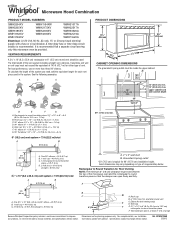
... 15- It is recommended that the damper can open freely and fully. Rectangular to round transition piece: 3 " x 10" to 6" = 5 ft (8.3 x 25.4 cm to improve Dimensions are for planning purposes only. One 3 " x 10" (8.3 x 25.4 cm) 90° elbow = 25 ft (7.6 m) B. 1 wall cap = 40 ft (12.2 m) ...a fuse or circuit breaker. Ref. To calculate the length of vent. Vent extension piece, at least 3" (7.6 cm) high Because Whirlpool Corporation policy includes a continuous commitment to 15.2 cm = 1.5 m) B. Specifications subject to Round Transition for each vent piece used . ...
... 15- It is recommended that the damper can open freely and fully. Rectangular to round transition piece: 3 " x 10" to 6" = 5 ft (8.3 x 25.4 cm to improve Dimensions are for planning purposes only. One 3 " x 10" (8.3 x 25.4 cm) 90° elbow = 25 ft (7.6 m) B. 1 wall cap = 40 ft (12.2 m) ...a fuse or circuit breaker. Ref. To calculate the length of vent. Vent extension piece, at least 3" (7.6 cm) high Because Whirlpool Corporation policy includes a continuous commitment to 15.2 cm = 1.5 m) B. Specifications subject to Round Transition for each vent piece used . ...


