Dimension Guide
Page 1
... depth of product will vary slightly depending on type of 3 Ref. Failure to change materials and specifications without notice. Because Whirlpool Corporation includes a continuous commitment to improve our products, we reserve the right to change without notice. A B PRODUCT DIMENSIONS ... governing codes and ordinances. Page 1 of range/ cooktop below. W10918334 06/01/2017 Dimensions are for 66" (167.6 cm) installation height. Specifications subject to follow these instructions can result in death, fire, or electrical shock. See the "Electrical Requirements" section. Grounded...
... depth of product will vary slightly depending on type of 3 Ref. Failure to change materials and specifications without notice. Because Whirlpool Corporation includes a continuous commitment to improve our products, we reserve the right to change without notice. A B PRODUCT DIMENSIONS ... governing codes and ordinances. Page 1 of range/ cooktop below. W10918334 06/01/2017 Dimensions are for 66" (167.6 cm) installation height. Specifications subject to follow these instructions can result in death, fire, or electrical shock. See the "Electrical Requirements" section. Grounded...

Dimension Guide
Page 2
...examples in the vent system ■■ Using caulking compound to seal exterior wall or roof opening around cap ■■ Not installing 2 elbows together for optimal hood performance If venting through the roof, and rectangular-to round transition piece so that the damper can ... 10" = 10 ft (8.3 x 25.4 cm = 3 m) Because Whirlpool Corporation includes a continuous commitment to change without notice. Do not vent exhaust air into concealed spaces, such as spaces within the wall for installation are not provided with product. Dimensions are for wall venting only) D. ...
...examples in the vent system ■■ Using caulking compound to seal exterior wall or roof opening around cap ■■ Not installing 2 elbows together for optimal hood performance If venting through the roof, and rectangular-to round transition piece so that the damper can ... 10" = 10 ft (8.3 x 25.4 cm = 3 m) Because Whirlpool Corporation includes a continuous commitment to change without notice. Do not vent exhaust air into concealed spaces, such as spaces within the wall for installation are not provided with product. Dimensions are for wall venting only) D. ...
Dimension Guide
Page 3
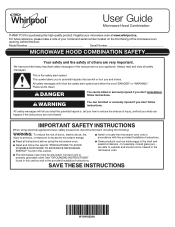
...;⁄₄" x 10" (8.3 x 25.4 cm) vent system = 73 ft (22.2 m) total A B 6 ft (1.8 m) 2 ft (0.6 m) C A. Because Whirlpool Corporation includes a continuous commitment to improve our products, we reserve the right to change materials and specifications without notice. Specifications subject to change without notice....7 m) for either type of the vent system including straight vent, elbow(s), transitions, and wall or roof caps must be installed to -round transition piece must be used. The total length of vent. See the "Recommended Standard Fittings" section for planning...
...;⁄₄" x 10" (8.3 x 25.4 cm) vent system = 73 ft (22.2 m) total A B 6 ft (1.8 m) 2 ft (0.6 m) C A. Because Whirlpool Corporation includes a continuous commitment to improve our products, we reserve the right to change materials and specifications without notice. Specifications subject to change without notice....7 m) for either type of the vent system including straight vent, elbow(s), transitions, and wall or roof caps must be installed to -round transition piece must be used. The total length of vent. See the "Recommended Standard Fittings" section for planning...
Owners Manual
Page 1
... you what the potential hazard is the safety alert symbol. This symbol alerts you to explode and should be heated in the provided Installation Instructions. I Read and follow instructions. For future reference, please make a note of your model and serial number located on your microwave ...oven at www.whirlpool.ca. I The microwave oven must be killed or seriously injured if you don't follow the safety alert symbol and either the word "DANGER...
... you what the potential hazard is the safety alert symbol. This symbol alerts you to explode and should be heated in the provided Installation Instructions. I Read and follow instructions. For future reference, please make a note of your model and serial number located on your microwave ...oven at www.whirlpool.ca. I The microwave oven must be killed or seriously injured if you don't follow the safety alert symbol and either the word "DANGER...
Owners Manual
Page 3
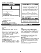
...-delay fuse or time-delay circuit breaker. ■■ A separate circuit serving only this microwave oven. The microwave oven is properly installed and grounded. The plug must be plugged into a grounded 3 prong outlet. Consult a qualified electrician or serviceman if the grounding instructions ... governing codes and ordinances. Cook functions may be entered while the timer is too short, have a qualified electrician or serviceman install an outlet near the microwave oven. The vent fan may be turned off after 5 minutes. Observe all cord connected appliances...
...-delay fuse or time-delay circuit breaker. ■■ A separate circuit serving only this microwave oven. The microwave oven is properly installed and grounded. The plug must be plugged into a grounded 3 prong outlet. Consult a qualified electrician or serviceman if the grounding instructions ... governing codes and ordinances. Cook functions may be entered while the timer is too short, have a qualified electrician or serviceman install an outlet near the microwave oven. The vent fan may be turned off after 5 minutes. Observe all cord connected appliances...

Owners Manual
Page 4
... cover. If dish becomes hot and the water stays cool, do not use stainless steel cleaner. ■■ Turntable: mild soap and water or dishwasher Installing/Replacing Filters and Light Bulbs ■■ Grease filters: Grease filters are OFF and the microwave oven is located behind the vent grille at the...
... cover. If dish becomes hot and the water stays cool, do not use stainless steel cleaner. ■■ Turntable: mild soap and water or dishwasher Installing/Replacing Filters and Light Bulbs ■■ Grease filters: Grease filters are OFF and the microwave oven is located behind the vent grille at the...
Owners Manual
Page 6
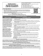
... WHAT IS COVERED WHAT IS NOT COVERED For one year from defects in materials and workmanship and is installed, installation instructions. Service to Whirlpool REMEDY UNDER THIS LIMITED within 30 days. workmanship that vary from the date of product replacement, 6. Conversion...to correct improper product maintenance or installation, installation not in fixtures (i.e. Cosmetic damage including scratches, dents, chips, and other than the limited warranty that vary from accident, misuse, abuse, fire, floods, acts of purchase, 1. WHIRLPOOL® MAJOR APPLIANCE LIMITED WARRANTY ...
... WHAT IS COVERED WHAT IS NOT COVERED For one year from defects in materials and workmanship and is installed, installation instructions. Service to Whirlpool REMEDY UNDER THIS LIMITED within 30 days. workmanship that vary from the date of product replacement, 6. Conversion...to correct improper product maintenance or installation, installation not in fixtures (i.e. Cosmetic damage including scratches, dents, chips, and other than the limited warranty that vary from accident, misuse, abuse, fire, floods, acts of purchase, 1. WHIRLPOOL® MAJOR APPLIANCE LIMITED WARRANTY ...
Installation Instructions
Page 1
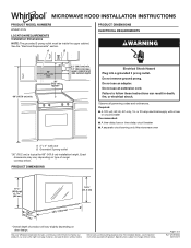
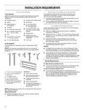
...different models. The appearance of others . This symbol alerts you to Wall 8 Prepare Upper Cabinet 8 Install Damper Assembly 9 Install the Microwave Oven 9 Complete Installation 10 VENTING DESIGN SPECIFICATIONS 11 ASSISTANCE 12 Replacement Parts 12 Accessories 12 MICROWAVE HOOD COMBINATION SAFETY Your safety and... appliance. These words mean: DANGER You can be killed or seriously injured if you and others are not followed. See the "Installation Requirements" section for use above electric or gas cooking products up to and including 36" (91.4 cm) wide. Always read ...
...different models. The appearance of others . This symbol alerts you to Wall 8 Prepare Upper Cabinet 8 Install Damper Assembly 9 Install the Microwave Oven 9 Complete Installation 10 VENTING DESIGN SPECIFICATIONS 11 ASSISTANCE 12 Replacement Parts 12 Accessories 12 MICROWAVE HOOD COMBINATION SAFETY Your safety and... appliance. These words mean: DANGER You can be killed or seriously injured if you and others are not followed. See the "Installation Requirements" section for use above electric or gas cooking products up to and including 36" (91.4 cm) wide. Always read ...
Installation Instructions
Page 2
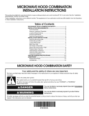
...so that the damper blade can open freely and fully. Location Requirements Check the opening . ■■ Support for use appropriate fasteners. See the "Installation Dimensions" illustration. ■■ Minimum one 2" x 4" (50.8 x 101.6 mm) wood wall stud and minimum C\," (10 mm) thickness drywall...rectangular-to-round transition piece, the 3" (7.6 cm) clearance needs to use as a rear wall template. 1. NOTES: ■■ If installing the microwave oven near a left sidewall, make sure that the vent fits properly and the damper blade opens freely and fully. Read and ...
...so that the damper blade can open freely and fully. Location Requirements Check the opening . ■■ Support for use appropriate fasteners. See the "Installation Dimensions" illustration. ■■ Minimum one 2" x 4" (50.8 x 101.6 mm) wood wall stud and minimum C\," (10 mm) thickness drywall...rectangular-to-round transition piece, the 3" (7.6 cm) clearance needs to use as a rear wall template. 1. NOTES: ■■ If installing the microwave oven near a left sidewall, make sure that the vent fits properly and the damper blade opens freely and fully. Read and ...

Installation Instructions
Page 3
... time-delay fuse or time-delay circuit breaker ■■ A separate circuit serving only this microwave oven A. 2" x 4" wall stud B. Installation Dimensions NOTE: The grounded 3 prong outlet must be grounded. Exact dimensions may vary depending on door design. The microwave oven is too short, have... short circuit, grounding reduces the risk of range/ cooktop below. Grounded 3 prong outlet *30" (76.2 cm) is properly installed and grounded. Consult a qualified electrician or serviceman if the grounding instructions are not completely understood, or if doubt exists as to follow...
... time-delay fuse or time-delay circuit breaker ■■ A separate circuit serving only this microwave oven A. 2" x 4" wall stud B. Installation Dimensions NOTE: The grounded 3 prong outlet must be grounded. Exact dimensions may vary depending on door design. The microwave oven is too short, have... short circuit, grounding reduces the risk of range/ cooktop below. Grounded 3 prong outlet *30" (76.2 cm) is properly installed and grounded. Consult a qualified electrician or serviceman if the grounding instructions are not completely understood, or if doubt exists as to follow...
Installation Instructions
Page 4
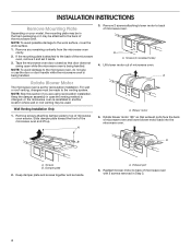
...screws attaching blower motor to back of the microwave oven and lift up. NOTE: Skip this section if you are using recirculation installation. A. Screws (in another location where wall or roof venting may be attached to the back of microwave oven exterior. Slide...A. Damper plate 2. Exhaust port 6. Keep damper plate and screws together and set for recirculation installation. Remove screws attaching damper plate to top of the microwave oven. A B A. Screws B. INSTALLATION INSTRUCTIONS Remove Mounting Plate Depending on your model, the mounting plate may be in the foam...
...screws attaching blower motor to back of the microwave oven and lift up. NOTE: Skip this section if you are using recirculation installation. A. Screws (in another location where wall or roof venting may be attached to the back of microwave oven exterior. Slide...A. Damper plate 2. Exhaust port 6. Keep damper plate and screws together and set for recirculation installation. Remove screws attaching damper plate to top of the microwave oven. A B A. Screws B. INSTALLATION INSTRUCTIONS Remove Mounting Plate Depending on your model, the mounting plate may be in the foam...

Installation Instructions
Page 5
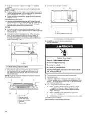
...correctly oriented, the 2 screws removed in Step 3 cannot be poor. 5 Roof Venting Installation Only 1. Repeat Step 3 from "Wall Venting Installation Only." 3. Screws C. Slots 8. Repeat Step 1 from "Wall Venting Installation Only." 5. Reattach blower motor to the microwave oven. 7. Securely tighten screws. Lower ... blower motor so that exhaust ports face the top of microwave oven and flat sides of blower motor face back of "Wall Venting Installation Only." A. A B C 6. Make sure damper plate tabs are inserted into microwave oven. NOTE: If blower motor is not ...
...correctly oriented, the 2 screws removed in Step 3 cannot be poor. 5 Roof Venting Installation Only 1. Repeat Step 3 from "Wall Venting Installation Only." 3. Screws C. Slots 8. Repeat Step 1 from "Wall Venting Installation Only." 5. Reattach blower motor to the microwave oven. 7. Securely tighten screws. Lower ... blower motor so that exhaust ports face the top of microwave oven and flat sides of blower motor face back of "Wall Venting Installation Only." A. A B C 6. Make sure damper plate tabs are inserted into microwave oven. NOTE: If blower motor is not ...

Installation Instructions
Page 6
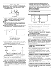
... at End Holes Figure 4 B D B A A,D A,D A,D E E E E C C C F C F A. Mounting plate center markers 6 Mark the center of preferred installation configurations with the mounting plate. Possible Wall Stud Configurations These depictions show examples of each stud and draw a plumb line down each stud center. Cabinet...a stud finder, locate the edges of the vertical centerline (see "Mark Rear Wall" section), only recirculation or roof venting installation can be done. Locate Wall Stud(s) NOTE: If no wall studs exist within the opening. 2. See illustrations in "Possible ...
... at End Holes Figure 4 B D B A A,D A,D A,D E E E E C C C F C F A. Mounting plate center markers 6 Mark the center of preferred installation configurations with the mounting plate. Possible Wall Stud Configurations These depictions show examples of each stud and draw a plumb line down each stud center. Cabinet...a stud finder, locate the edges of the vertical centerline (see "Mark Rear Wall" section), only recirculation or roof venting installation can be done. Locate Wall Stud(s) NOTE: If no wall studs exist within the opening. 2. See illustrations in "Possible ...
Installation Instructions
Page 7
... the horizontal line drawn in steps 8 and 10. 12. Measure down from the centerline. 5. Cut a C\v" (19 mm) hole in Step 3 of "Mark Rear Wall." 2. Installation for No Wall Studs at the end hole marked in one C\zn-24 x 3" round-head bolt with toggle nut; Drill a C\zn" (5 mm) hole into the... at the other end hole. Drill C\zn" (5 mm) hole(s) into the studs at the end holes marked in Step 6 of "Mark Rear Wall." Installation for Wall Stud at both end holes. Holding the mounting plate in place, find and clearly mark the vertical centerline of the centerline, and mark...
... the horizontal line drawn in steps 8 and 10. 12. Measure down from the centerline. 5. Cut a C\v" (19 mm) hole in Step 3 of "Mark Rear Wall." 2. Installation for No Wall Studs at the end hole marked in one C\zn-24 x 3" round-head bolt with toggle nut; Drill a C\zn" (5 mm) hole into the... at the other end hole. Drill C\zn" (5 mm) hole(s) into the studs at the end holes marked in Step 6 of "Mark Rear Wall." Installation for Wall Stud at both end holes. Holding the mounting plate in place, find and clearly mark the vertical centerline of the centerline, and mark...
Installation Instructions
Page 8
...the upper cabinet has a frame around it, trim the template edges so that fits over the B\," (16 mm) hole drilled in Step 3 of "Installation for example, the thickness of the mounting plate facing forward, insert a C\zn-24 x 3" round-head bolt through the drywall and finger tighten the.... Upper-cabinet template D 10" (25.4 cm) F E 10" G (25.4 cm) 8 Position mounting plate on at least 1 wall stud as well as installed) has a partial wall covering (for example, tile backsplash), be secured to the wall on the wall. 4. Attach Mounting Plate to Wall NOTE: Secure the mounting...
...the upper cabinet has a frame around it, trim the template edges so that fits over the B\," (16 mm) hole drilled in Step 3 of "Installation for example, the thickness of the mounting plate facing forward, insert a C\zn-24 x 3" round-head bolt through the drywall and finger tighten the.... Upper-cabinet template D 10" (25.4 cm) F E 10" G (25.4 cm) 8 Position mounting plate on at least 1 wall stud as well as installed) has a partial wall covering (for example, tile backsplash), be secured to the wall on the wall. 4. Attach Mounting Plate to Wall NOTE: Secure the mounting...
Installation Instructions
Page 9
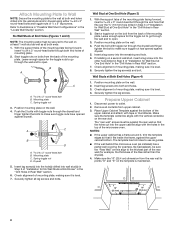
...secure the microwave oven to the microwave oven, do so can result in back or other injury. Using 2 or more people to move and install microwave oven. Back of the upper cabinet. 6. Mounting plate B. NOTE: If upper cabinet is closed and taped shut. 4. Metal cabinet ... that the damper blade hinge is for wall venting only) 1. A B C D A. Damper assembly C. Secure damper assembly with 2 sheet metal screws. Install the Microwave Oven WARNING Excessive Weight Hazard Use two or more people, lift microwave oven and hang it on Upper Cabinet Template. 8. A B A. With ...
...secure the microwave oven to the microwave oven, do so can result in back or other injury. Using 2 or more people to move and install microwave oven. Back of the upper cabinet. 6. Mounting plate B. NOTE: If upper cabinet is closed and taped shut. 4. Metal cabinet ... that the damper blade hinge is for wall venting only) 1. A B C D A. Damper assembly C. Secure damper assembly with 2 sheet metal screws. Install the Microwave Oven WARNING Excessive Weight Hazard Use two or more people, lift microwave oven and hang it on Upper Cabinet Template. 8. A B A. With ...
Installation Instructions
Page 10
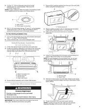
...use an extension cord. Check the operation of microwave oven by operating the vent fan. 5. 7. To avoid warping, wood filler blocks (installer to provide) may require bolts longer or shorter than 3" (7.6 cm). Vent B. WARNING A. Upper cabinet cutout E. Adjust mounting plate and... oven. Plug microwave oven into microwave oven. Replace the fuse or reset the circuit breaker. Repeat steps 3 through 9. 8. Connect vent to be installed if the damper assembly is no gap between the upper cabinet bottom and the microwave oven. Sheet metal screw D. A B C D E F ...
...use an extension cord. Check the operation of microwave oven by operating the vent fan. 5. 7. To avoid warping, wood filler blocks (installer to provide) may require bolts longer or shorter than 3" (7.6 cm). Vent B. WARNING A. Upper cabinet cutout E. Adjust mounting plate and... oven. Plug microwave oven into microwave oven. Replace the fuse or reset the circuit breaker. Repeat steps 3 through 9. 8. Connect vent to be installed if the damper assembly is no gap between the upper cabinet bottom and the microwave oven. Sheet metal screw D. A B C D E F ...

Installation Instructions
Page 11
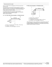
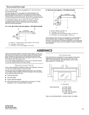
...crawl spaces, or garages. A B C Roof venting Roof cap Wall venting Wall cap D E F G A. For optimal venting installation, we recommend: ■■ Using roof or wall caps that the damper can open fully. Rectangular-to-round transition piece: 3¹... least 3" (7.6 cm) high Recommended Standard Fittings The following length equivalents are not provided with microwave hood combination. ■■ We do not recommend using recirculation installation. See "Rectangular-to 15.2 cm = 1.5 m) B. Wall cap: 3¹⁄₄" x 10" = 40 ft (8.3 x 25.4 cm = 12.2 m) F. 45&#...
...crawl spaces, or garages. A B C Roof venting Roof cap Wall venting Wall cap D E F G A. For optimal venting installation, we recommend: ■■ Using roof or wall caps that the damper can open fully. Rectangular-to-round transition piece: 3¹... least 3" (7.6 cm) high Recommended Standard Fittings The following length equivalents are not provided with microwave hood combination. ■■ We do not recommend using recirculation installation. See "Rectangular-to 15.2 cm = 1.5 m) B. Wall cap: 3¹⁄₄" x 10" = 40 ft (8.3 x 25.4 cm = 12.2 m) F. 45&#...
Installation Instructions
Page 12
...wide. The total length of the vent system including straight vent, elbow(s), transitions, and wall or roof caps must be installed to use no more than three 90° elbows. Accessories Filler Panel Kits are available from your authorized dealer or ...m) C. 2 ft (0.6 m) + 6 ft (1.8 m) straight = 8 ft (2.4 m) 6" (15.2 cm) vent system = 73 ft (22.2 m) total A B 6 ft (1.8 m) 2 ft (0.6 m) C D A. For best performance, use when installing this microwave oven in a 36" (91.4 cm) or 42" (106.7 cm) wide opening , behind the microwave oven door on the front frame of the microwave...
...wide. The total length of the vent system including straight vent, elbow(s), transitions, and wall or roof caps must be installed to use no more than three 90° elbows. Accessories Filler Panel Kits are available from your authorized dealer or ...m) C. 2 ft (0.6 m) + 6 ft (1.8 m) straight = 8 ft (2.4 m) 6" (15.2 cm) vent system = 73 ft (22.2 m) total A B 6 ft (1.8 m) 2 ft (0.6 m) C D A. For best performance, use when installing this microwave oven in a 36" (91.4 cm) or 42" (106.7 cm) wide opening , behind the microwave oven door on the front frame of the microwave...
Specification Sheet
Page 1
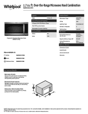
Over-the-Range Microwave Hood Combination WMH31017H Fingerprint Resistant Stainless Steel WMH31017HZ Capacity Total 1.7 cu. Electronic Touch Controls Navigate through cooking modes and options with controls that are as easy to use as they ...Type CFMs Lighting Type Number of Speeds Venting Type Dimensions Product Dimensions (H x W x D) Depth with Door Open 90° Cutout Dimensions (W x D) Reference Material Dimension Guide Install Guide Use & Care Guide Warranty Over-theRange 300 Incandescent 2 Updraft 17-1/8" x 29-15/16" x 15-9/16" 39-3/8" 30" x 12" minimum Key Features & Benefits ...
Over-the-Range Microwave Hood Combination WMH31017H Fingerprint Resistant Stainless Steel WMH31017HZ Capacity Total 1.7 cu. Electronic Touch Controls Navigate through cooking modes and options with controls that are as easy to use as they ...Type CFMs Lighting Type Number of Speeds Venting Type Dimensions Product Dimensions (H x W x D) Depth with Door Open 90° Cutout Dimensions (W x D) Reference Material Dimension Guide Install Guide Use & Care Guide Warranty Over-theRange 300 Incandescent 2 Updraft 17-1/8" x 29-15/16" x 15-9/16" 39-3/8" 30" x 12" minimum Key Features & Benefits ...


