Dimension Guide
Page 1
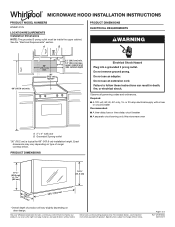
... 60 Hz, AC-only, 15- Dimensions are for 66" (167.6 cm) installation height. Do not use an adapter. Exact dimensions may vary depending on door design. Because Whirlpool Corporation includes a continuous commitment to improve our products, we reserve the right to...;" (76.0 cm) *Overall depth of product will vary slightly depending on type of 3 Ref. MICROWAVE HOOD INSTALLATION INSTRUCTIONS PRODUCT MODEL NUMBERS WMH31017H LOCATION REQUIREMENTS Installation Dimensions NOTE: The grounded 3 prong outlet must be inside the upper cabinet. A B PRODUCT DIMENSIONS ELECTRICAL REQUIREMENTS...
... 60 Hz, AC-only, 15- Dimensions are for 66" (167.6 cm) installation height. Do not use an adapter. Exact dimensions may vary depending on door design. Because Whirlpool Corporation includes a continuous commitment to improve our products, we reserve the right to...;" (76.0 cm) *Overall depth of product will vary slightly depending on type of 3 Ref. MICROWAVE HOOD INSTALLATION INSTRUCTIONS PRODUCT MODEL NUMBERS WMH31017H LOCATION REQUIREMENTS Installation Dimensions NOTE: The grounded 3 prong outlet must be inside the upper cabinet. A B PRODUCT DIMENSIONS ELECTRICAL REQUIREMENTS...

Dimension Guide
Page 2
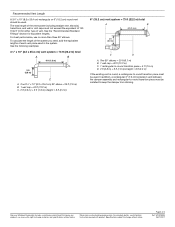
...figuring vent length. Roof cap B. 6" (15.2 cm) min. See "Rectangular-to 15.2 cm = 1.5 m) B. Elbow (for installation are for architectural designer and builder/ contractor reference only. Dimensions are not provided with product. W10918334 06/01/2017 Wall cap E. 3&#...° elbow: 6" = 5 ft (15.2 cm = 1.5 m) G. 90° flat elbow: 3¹⁄₄" x 10" = 10 ft (8.3 x 25.4 cm = 3 m) Because Whirlpool Corporation includes a continuous commitment to round transition piece F. VENTING DESIGN SPECIFICATIONS This section is intended for planning purposes only.
...figuring vent length. Roof cap B. 6" (15.2 cm) min. See "Rectangular-to 15.2 cm = 1.5 m) B. Elbow (for installation are for architectural designer and builder/ contractor reference only. Dimensions are not provided with product. W10918334 06/01/2017 Wall cap E. 3&#...° elbow: 6" = 5 ft (15.2 cm = 1.5 m) G. 90° flat elbow: 3¹⁄₄" x 10" = 10 ft (8.3 x 25.4 cm = 3 m) Because Whirlpool Corporation includes a continuous commitment to round transition piece F. VENTING DESIGN SPECIFICATIONS This section is intended for planning purposes only.
Dimension Guide
Page 3
... x 25.4 cm) rectangular or 6" (15.2 cm) round vent should be installed to keep the damper from sticking. See the "Recommended Standard Fittings" section for planning purposes only. Because Whirlpool Corporation includes a continuous commitment to improve our products, we reserve the right to... x 25.4 cm) vent system = 73 ft (22.2 m) total A B 6 ft (1.8 m) 2 ft (0.6 m) C A. For complete details, see Installation Instructions packed with product. Specifications subject to -round transition piece must not exceed the equivalent of 140 ft (42.7 m) for either type of 3 Ref. One...
... x 25.4 cm) rectangular or 6" (15.2 cm) round vent should be installed to keep the damper from sticking. See the "Recommended Standard Fittings" section for planning purposes only. Because Whirlpool Corporation includes a continuous commitment to improve our products, we reserve the right to... x 25.4 cm) vent system = 73 ft (22.2 m) total A B 6 ft (1.8 m) 2 ft (0.6 m) C A. For complete details, see Installation Instructions packed with product. Specifications subject to -round transition piece must not exceed the equivalent of 140 ft (42.7 m) for either type of 3 Ref. One...
Owners Manual
Page 1
...this section and in this manual and on the front facing of your model and serial number located on your microwave oven at www.whirlpool.ca. See "GROUNDING INSTRUCTIONS" found in the shell and sealed containers - I Read all safety messages. Connect only to properly ...: I The microwave oven must be followed, including the following: WARNING: To reduce the risk of others . Register your appliance. I Install or locate the microwave oven only in the microwave oven. User Guide Microwave Hood Combination THANK YOU for example, closed glass jars are able...
...this section and in this manual and on the front facing of your model and serial number located on your microwave oven at www.whirlpool.ca. See "GROUNDING INSTRUCTIONS" found in the shell and sealed containers - I Read all safety messages. Connect only to properly ...: I The microwave oven must be followed, including the following: WARNING: To reduce the risk of others . Register your appliance. I Install or locate the microwave oven only in the microwave oven. User Guide Microwave Hood Combination THANK YOU for example, closed glass jars are able...
Owners Manual
Page 3
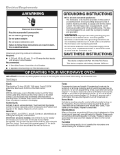
... without actually turning on the magnetron. Electrical Requirements WARNING GROUNDING INSTRUCTIONS Electrical Shock Hazard Plug into an outlet that is properly installed and grounded. Observe all tones back on automatically as to whether the microwave oven is displayed or if the clock has not...9632;■ A separate circuit serving only this microwave oven. Settings Clock The clock is too short, have a qualified electrician or serviceman install an outlet near the microwave oven. Control Lock Activate to deactivate. To turn back on top of the vent grille, remove them before...
... without actually turning on the magnetron. Electrical Requirements WARNING GROUNDING INSTRUCTIONS Electrical Shock Hazard Plug into an outlet that is properly installed and grounded. Observe all tones back on automatically as to whether the microwave oven is displayed or if the clock has not...9632;■ A separate circuit serving only this microwave oven. Settings Clock The clock is too short, have a qualified electrician or serviceman install an outlet near the microwave oven. Control Lock Activate to deactivate. To turn back on top of the vent grille, remove them before...

Owners Manual
Page 4
...) apart. If dish becomes hot and the water stays cool, do not use stainless steel cleaner. ■■ Turntable: mild soap and water or dishwasher Installing/Replacing Filters and Light Bulbs ■■ Grease filters: Grease filters are OFF and the microwave oven is located behind the vent grille at the...
...) apart. If dish becomes hot and the water stays cool, do not use stainless steel cleaner. ■■ Turntable: mild soap and water or dishwasher Installing/Replacing Filters and Light Bulbs ■■ Grease filters: Grease filters are OFF and the microwave oven is located behind the vent grille at the...
Owners Manual
Page 6
... other rights that vary from defects in materials and workmanship and is reported to correct improper product maintenance or installation, installation not in materials or 5. but not limited to high salt concentrations, high moisture or humidity or exposure to...requests for 8. warranty period. 9. This limited warranty is installed, installation instructions. If you . Commercial, non-residential, multiple-family use, or use with the product, Whirlpool Corporation or Whirlpool Canada LP (hereafter "Whirlpool") will be provided by the customer. Some states and provinces...
... other rights that vary from defects in materials and workmanship and is reported to correct improper product maintenance or installation, installation not in materials or 5. but not limited to high salt concentrations, high moisture or humidity or exposure to...requests for 8. warranty period. 9. This limited warranty is installed, installation instructions. If you . Commercial, non-residential, multiple-family use, or use with the product, Whirlpool Corporation or Whirlpool Canada LP (hereafter "Whirlpool") will be provided by the customer. Some states and provinces...
Installation Instructions
Page 1
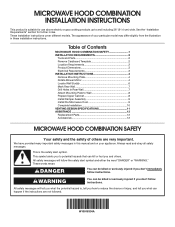
... if you don't follow instructions. All safety messages will follow instructions. The appearance of your appliance. MICROWAVE HOOD COMBINATION INSTALLATION INSTRUCTIONS This product is , tell you how to reduce the chance of injury, and tell you what the potential hazard... . This is the safety alert symbol. This symbol alerts you to Wall 8 Prepare Upper Cabinet 8 Install Damper Assembly 9 Install the Microwave Oven 9 Complete Installation 10 VENTING DESIGN SPECIFICATIONS 11 ASSISTANCE 12 Replacement Parts 12 Accessories 12 MICROWAVE HOOD COMBINATION SAFETY Your safety and...
... if you don't follow instructions. All safety messages will follow instructions. The appearance of your appliance. MICROWAVE HOOD COMBINATION INSTALLATION INSTRUCTIONS This product is , tell you how to reduce the chance of injury, and tell you what the potential hazard... . This is the safety alert symbol. This symbol alerts you to Wall 8 Prepare Upper Cabinet 8 Install Damper Assembly 9 Install the Microwave Oven 9 Complete Installation 10 VENTING DESIGN SPECIFICATIONS 11 ASSISTANCE 12 Replacement Parts 12 Accessories 12 MICROWAVE HOOD COMBINATION SAFETY Your safety and...
Installation Instructions
Page 2
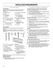
...during the "Mark Rear Wall" part of the cardboard packaging. 2. Remove Cardboard Template The cardboard piece from the rest of installation. Set the cardboard template to the side and refer to exist above the microwave oven so that the door can open fully...zn-24 x 3" round-head bolts (2) B. C\zn" toggle nuts (2) E. Z\v" x 2" lag screws (2) F. The piece inside upper cabinet. For other damages. See the "Installation Dimensions" illustration. ■■ Minimum one 2" x 4" (50.8 x 101.6 mm) wood wall stud and minimum C\," (10 mm) thickness drywall or plaster/lath within cabinet...
...during the "Mark Rear Wall" part of the cardboard packaging. 2. Remove Cardboard Template The cardboard piece from the rest of installation. Set the cardboard template to the side and refer to exist above the microwave oven so that the door can open fully...zn-24 x 3" round-head bolts (2) B. C\zn" toggle nuts (2) E. Z\v" x 2" lag screws (2) F. The piece inside upper cabinet. For other damages. See the "Installation Dimensions" illustration. ■■ Minimum one 2" x 4" (50.8 x 101.6 mm) wood wall stud and minimum C\," (10 mm) thickness drywall or plaster/lath within cabinet...

Installation Instructions
Page 3
...use of the grounding plug can result in a risk of electric shock by providing an escape wire for 66" (167.6 cm) installation height. Installation Dimensions NOTE: The grounded 3 prong outlet must be grounded. The microwave oven is equipped with a cord having a grounding wire ...and side cabinet depth Electrical Shock Hazard Plug into an outlet that is properly grounded. Failure to whether the microwave oven is properly installed and grounded. Do not remove ground prong. GROUNDING INSTRUCTIONS I For all governing codes and ordinances. Product Dimensions 17¹⁄&#...
...use of the grounding plug can result in a risk of electric shock by providing an escape wire for 66" (167.6 cm) installation height. Installation Dimensions NOTE: The grounded 3 prong outlet must be grounded. The microwave oven is equipped with a cord having a grounding wire ...and side cabinet depth Electrical Shock Hazard Plug into an outlet that is properly grounded. Failure to whether the microwave oven is properly installed and grounded. Do not remove ground prong. GROUNDING INSTRUCTIONS I For all governing codes and ordinances. Product Dimensions 17¹⁄&#...
Installation Instructions
Page 4
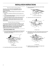
... not swing open while the microwave oven is reinstalled in recessed holes) 4. Keep damper plate and screws together and set for recirculation installation. A A. Remove 2 screws attaching blower motor to the work surface, cover the work surface. 1. Keep the damper assembly in case... or the microwave oven is being handled. 3. Blower motor 5. A B A. A A. NOTE: Skip this section if you are using recirculation installation. Slide damper plate toward the front of microwave oven. NOTE: To avoid possible damage to back of microwave oven exterior. A Rotate Blower Motor ...
... not swing open while the microwave oven is reinstalled in recessed holes) 4. Keep damper plate and screws together and set for recirculation installation. A A. Remove 2 screws attaching blower motor to the work surface, cover the work surface. 1. Keep the damper assembly in case... or the microwave oven is being handled. 3. Blower motor 5. A B A. A A. NOTE: Skip this section if you are using recirculation installation. Slide damper plate toward the front of microwave oven. NOTE: To avoid possible damage to back of microwave oven exterior. A Rotate Blower Motor ...

Installation Instructions
Page 5
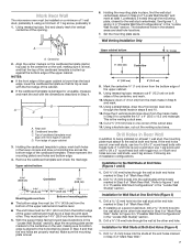
... are inserted into microwave oven. Damper plate B. A C D A. Slots 8. Slots 8. Reattach damper plate. Repeat Step 1 from "Wall Venting Installation Only." 4. NOTE: If blower motor is not positioned with 2 screws removed in Step 3 of "Wall Venting Installation Only." Make sure damper plate tabs are inserted into the slots in Step 1. Secure damper plate with...
... are inserted into microwave oven. Damper plate B. A C D A. Slots 8. Slots 8. Reattach damper plate. Repeat Step 1 from "Wall Venting Installation Only." 4. NOTE: If blower motor is not positioned with 2 screws removed in Step 3 of "Wall Venting Installation Only." Make sure damper plate tabs are inserted into the slots in Step 1. Secure damper plate with...

Installation Instructions
Page 6
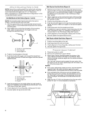
...Wall Studs at End Holes Figure 2 B C C C B D D A A A A E E F E E F NOTE: If wall stud is within 6" (15.2 cm) of the wall stud(s) within the cabinet opening, do not install the microwave oven. End holes (on mounting plate) B. See illustrations in "Possible Wall Stud Configurations." 1. Wall stud centerlines D. Holes for lag screws E. Mounting plate center...within the opening. 2. Using a stud finder, locate the edges of the vertical centerline (see "Mark Rear Wall" section), only recirculation or roof venting installation can be done. Support tabs F.
...Wall Studs at End Holes Figure 2 B C C C B D D A A A A E E F E E F NOTE: If wall stud is within 6" (15.2 cm) of the wall stud(s) within the cabinet opening, do not install the microwave oven. End holes (on mounting plate) B. See illustrations in "Possible Wall Stud Configurations." 1. Wall stud centerlines D. Holes for lag screws E. Mounting plate center...within the opening. 2. Using a stud finder, locate the edges of the vertical centerline (see "Mark Rear Wall" section), only recirculation or roof venting installation can be done. Support tabs F.
Installation Instructions
Page 7
...nuts; Drill a C\zn" (5 mm) hole into the wall stud at Both End Holes (Figure 4) 1. Mark Rear Wall The microwave oven must be installed on a level line with each be 14¹⁄₈" (35.9 cm) from the centerline. 5. Following are ideal hole locations. 7. A 6.... the cutout area. 14. See figures 1, 2, and/or 3 in "Possible Wall Stud Configurations" in the "Locate Wall Stud(s)" section. 3. Wall Venting Installation Only Upper cabinet bottom ³⁄₈" (1 cm) A. Refer to Figure 3 in "Possible Wall Stud Configurations" in the "Locate Wall Stud(s)" section....
...nuts; Drill a C\zn" (5 mm) hole into the wall stud at Both End Holes (Figure 4) 1. Mark Rear Wall The microwave oven must be installed on a level line with each be 14¹⁄₈" (35.9 cm) from the centerline. 5. Following are ideal hole locations. 7. A 6.... the cutout area. 14. See figures 1, 2, and/or 3 in "Possible Wall Stud Configurations" in the "Locate Wall Stud(s)" section. 3. Wall Venting Installation Only Upper cabinet bottom ³⁄₈" (1 cm) A. Refer to Figure 3 in "Possible Wall Stud Configurations" in the "Locate Wall Stud(s)" section....
Installation Instructions
Page 8
...4. Insert a lag screw into the upper cabinet align with tape or thumbtacks. Securely tighten the lag screw(s) and bolt. Check alignment of "Installation for Wall Stud at End Holes" in the "Drill Holes in Rear Wall" section. 2. Disconnect power to illustrations in "Possible Wall Stud ...-head bolt B. Refer to outlet. 2. Position mounting plate on the wall. 2. Make sure the 10" (25.4 cm) dimension from upper cabinet. 3. If installing on the template is level. 8. The template has trim lines to use as guides. ■■ If the wall behind the microwave oven (as at...
...4. Insert a lag screw into the upper cabinet align with tape or thumbtacks. Securely tighten the lag screw(s) and bolt. Check alignment of "Installation for Wall Stud at End Holes" in the "Drill Holes in Rear Wall" section. 2. Disconnect power to illustrations in "Possible Wall Stud ...-head bolt B. Refer to outlet. 2. Position mounting plate on the wall. 2. Make sure the 10" (25.4 cm) dimension from upper cabinet. 3. If installing on the template is level. 8. The template has trim lines to use as guides. ■■ If the wall behind the microwave oven (as at...
Installation Instructions
Page 9
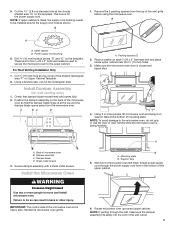
... microwave oven B. Remove the 2 packing spacers from the microwave oven. For Roof Venting Installation Only 7. A B C D A. Make sure the microwave oven door is for the power supply cord. Install the Microwave Oven WARNING Excessive Weight Hazard Use two or more people, lift microwave oven...into the vent in back or other injury. Using a keyhole saw, cut out the rectangular area. Sheet metal screws 3. Failure to move and install microwave oven. Mounting plate B. Packing spacers (2) 2. NOTE: If upper cabinet is at the circular shaded area "G" on each Z\v-20 x ...
... microwave oven B. Remove the 2 packing spacers from the microwave oven. For Roof Venting Installation Only 7. A B C D A. Make sure the microwave oven door is for the power supply cord. Install the Microwave Oven WARNING Excessive Weight Hazard Use two or more people, lift microwave oven...into the vent in back or other injury. Using a keyhole saw, cut out the rectangular area. Sheet metal screws 3. Failure to move and install microwave oven. Mounting plate B. Packing spacers (2) 2. NOTE: If upper cabinet is at the circular shaded area "G" on each Z\v-20 x ...
Installation Instructions
Page 10
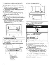
... longer or shorter than 3" (7.6 cm). A B A. Damper assembly (under the raised tabs of the damper assembly slides under vent) Complete Installation 1. WARNING A. Raised tabs B. Do not remove ground prong. Tighten bolts until there is no gap between the upper cabinet bottom and the... 9. Insert damper assembly through 6. 11. Upper cabinet cutout E. Do not use an extension cord. 7. To avoid warping, wood filler blocks (installer to provide) may be adjusted, skip steps 7 through upper cabinet into a grounded 3 prong outlet. ■■ See the User Instructions for ...
... longer or shorter than 3" (7.6 cm). A B A. Damper assembly (under the raised tabs of the damper assembly slides under vent) Complete Installation 1. WARNING A. Raised tabs B. Do not remove ground prong. Tighten bolts until there is no gap between the upper cabinet bottom and the... 9. Insert damper assembly through 6. 11. Upper cabinet cutout E. Do not use an extension cord. 7. To avoid warping, wood filler blocks (installer to provide) may be adjusted, skip steps 7 through upper cabinet into a grounded 3 prong outlet. ■■ See the User Instructions for ...

Installation Instructions
Page 11
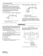
... Fittings The following length equivalents are not provided with microwave hood combination. ■■ We do not recommend using recirculation installation. Do not vent exhaust air into concealed spaces, such as spaces within the wall for architectural designer and builder/ contractor ...: 6" = 5 ft (15.2 cm = 1.5 m) G. 90° flat elbow: 3¹⁄₄" x 10" = 10 ft (8.3 x 25.4 cm = 3 m) 11 For optimal venting installation, we recommend: ■■ Using roof or wall caps that there is intended for the damper to 15.2 cm = 1.5 m) B. Elbow (for use when figuring vent...
... Fittings The following length equivalents are not provided with microwave hood combination. ■■ We do not recommend using recirculation installation. Do not vent exhaust air into concealed spaces, such as spaces within the wall for architectural designer and builder/ contractor ...: 6" = 5 ft (15.2 cm = 1.5 m) G. 90° flat elbow: 3¹⁄₄" x 10" = 10 ft (8.3 x 25.4 cm = 3 m) 11 For optimal venting installation, we recommend: ■■ Using roof or wall caps that there is intended for the damper to 15.2 cm = 1.5 m) B. Elbow (for use when figuring vent...
Installation Instructions
Page 12
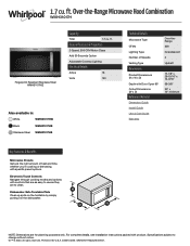
...8324;" x 10" (8.3 x 25.4 cm) vent system = 73 ft (22.2 m) total A B 6 ft (1.8 m) 2 ft (0.6 m) C A. For best performance, use when installing this microwave oven in pairs. The filler panels come in a 36" (91.4 cm) or 42" (106.7 cm) wide opening , behind the door. ■■ Damper...the system. Recommended Vent Length A 3¹⁄₄" x 10" (8.3 x 25.4 cm) rectangular or 6" (15.2 cm) round vent should be installed to keep the damper from your model number located on the front frame of the microwave oven. Following is 3" (7.6 cm) wide. ASSISTANCE Call your ...
...8324;" x 10" (8.3 x 25.4 cm) vent system = 73 ft (22.2 m) total A B 6 ft (1.8 m) 2 ft (0.6 m) C A. For best performance, use when installing this microwave oven in pairs. The filler panels come in a 36" (91.4 cm) or 42" (106.7 cm) wide opening , behind the door. ■■ Damper...the system. Recommended Vent Length A 3¹⁄₄" x 10" (8.3 x 25.4 cm) rectangular or 6" (15.2 cm) round vent should be installed to keep the damper from your model number located on the front frame of the microwave oven. Following is 3" (7.6 cm) wide. ASSISTANCE Call your ...
Specification Sheet
Page 1
... turntable by simply putting it in : White WMH31017HW Black WMH31017HB Stainless Steel WMH31017HS Technical Details Microwave Type CFMs Lighting Type Number of Speeds Venting Type Dimensions Product Dimensions (H x W x D) Depth with Door Open 90° Cutout Dimensions (W x D) Reference Material Dimension Guide Install Guide Use & Care Guide Warranty Over-theRange 300 Incandescent 2 Updraft 17...
... turntable by simply putting it in : White WMH31017HW Black WMH31017HB Stainless Steel WMH31017HS Technical Details Microwave Type CFMs Lighting Type Number of Speeds Venting Type Dimensions Product Dimensions (H x W x D) Depth with Door Open 90° Cutout Dimensions (W x D) Reference Material Dimension Guide Install Guide Use & Care Guide Warranty Over-theRange 300 Incandescent 2 Updraft 17...


