Dimension Guide
Page 1
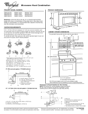
... ft (12.2 m) C. 1 rectangular to round transition piece F. Vent extension piece, at least 3" (7.6 cm) high Because Whirlpool Corporation policy includes a continuous commitment to Round Transition for 66" (167.6 cm) installation height. W10247296B 9/30/10 Wall cap: 3 " x 10" = 40 ft (8.3 x 25.4 cm = 12.2 m)... Roof cap B. 6" (15.2 cm) min. ® Microwave Hood Combination PRODUCT MODEL NUMBERS GMH3204XV GMH5205XV GMH6185XV WMH1162XV WMH1163XV WMH1164XW WMH2175XV WMH2205XV WMH3205XV Electrical: A 120-Volt, 60-Hz, AC-only, 15- Rectangular to round transition piece: 3...
... ft (12.2 m) C. 1 rectangular to round transition piece F. Vent extension piece, at least 3" (7.6 cm) high Because Whirlpool Corporation policy includes a continuous commitment to Round Transition for 66" (167.6 cm) installation height. W10247296B 9/30/10 Wall cap: 3 " x 10" = 40 ft (8.3 x 25.4 cm = 12.2 m)... Roof cap B. 6" (15.2 cm) min. ® Microwave Hood Combination PRODUCT MODEL NUMBERS GMH3204XV GMH5205XV GMH6185XV WMH1162XV WMH1163XV WMH1164XW WMH2175XV WMH2205XV WMH3205XV Electrical: A 120-Volt, 60-Hz, AC-only, 15- Rectangular to round transition piece: 3...

Installation Instructions
Page 1
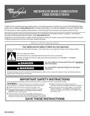
...of your appliance. All safety messages will follow instructions. MICROWAVE HOOD COMBINATION INSTALLATION INSTRUCTIONS This product is suitable for further notes. See "Installation Requirements" section for use above electric or gas cooking products up to ...SAFETY Your safety and the safety of Contents MICROWAVE HOOD COMBINATION SAFETY 1 INSTALLATION REQUIREMENTS 2 Tools and Parts 2 Remove Cardboard Template 2 Location Requirements 2 Product Dimensions 3 Electrical Requirements 3 INSTALLATION INSTRUCTIONS 4 Remove Mounting Plate 4 Rotate Blower Motor 4 Locate Wall Stud...
...of your appliance. All safety messages will follow instructions. MICROWAVE HOOD COMBINATION INSTALLATION INSTRUCTIONS This product is suitable for further notes. See "Installation Requirements" section for use above electric or gas cooking products up to ...SAFETY Your safety and the safety of Contents MICROWAVE HOOD COMBINATION SAFETY 1 INSTALLATION REQUIREMENTS 2 Tools and Parts 2 Remove Cardboard Template 2 Location Requirements 2 Product Dimensions 3 Electrical Requirements 3 INSTALLATION INSTRUCTIONS 4 Remove Mounting Plate 4 Rotate Blower Motor 4 Locate Wall Stud...

Installation Instructions
Page 2
... perforation is for 1/4" x 2" lag screws ■ Scissors ■ 1½" (3.8 cm) diam. Sheet metal screws (2) G. Power supply cord bushing (1) H. See "Installation Dimensions" illustration. ■ Minimum one 2" x 4" (50.8 x 101.6 mm) wood wall stud and minimum 3/8" (10 mm) thickness drywall or plaster/lath within cabinet... to exist above the microwave oven so that the vent fits properly, and the damper blade opens freely and fully. For Roof Venting Installation Only: ■ If you are using a rectangular to round transition piece, the 3" (7.6 cm) clearance needs to use as a...
... perforation is for 1/4" x 2" lag screws ■ Scissors ■ 1½" (3.8 cm) diam. Sheet metal screws (2) G. Power supply cord bushing (1) H. See "Installation Dimensions" illustration. ■ Minimum one 2" x 4" (50.8 x 101.6 mm) wood wall stud and minimum 3/8" (10 mm) thickness drywall or plaster/lath within cabinet... to exist above the microwave oven so that the vent fits properly, and the damper blade opens freely and fully. For Roof Venting Installation Only: ■ If you are using a rectangular to round transition piece, the 3" (7.6 cm) clearance needs to use as a...

Installation Instructions
Page 3
... A 120 Volt, 60 Hz, AC only, 15- or 20-amp electrical supply with a grounding plug. Grounded 3 prong outlet *30" (76.2 cm) is properly installed and grounded. Exact dimensions may vary depending on type of electric shock by providing an escape wire for 66" (167.6 cm...30" (76.2 cm) typical* 12" (30.5 cm) min. 14" (35.6 cm) max. Do not use of electric shock. The microwave oven is properly grounded. Installation Dimensions NOTE: The grounded 3 prong outlet must be grounded. Do not remove ground prong. A. 2" x 4" wall stud B. Product Dimensions 17¹⁄₄" (43.8 cm...
... A 120 Volt, 60 Hz, AC only, 15- or 20-amp electrical supply with a grounding plug. Grounded 3 prong outlet *30" (76.2 cm) is properly installed and grounded. Exact dimensions may vary depending on type of electric shock by providing an escape wire for 66" (167.6 cm...30" (76.2 cm) typical* 12" (30.5 cm) min. 14" (35.6 cm) max. Do not use of electric shock. The microwave oven is properly grounded. Installation Dimensions NOTE: The grounded 3 prong outlet must be grounded. Do not remove ground prong. A. 2" x 4" wall stud B. Product Dimensions 17¹⁄₄" (43.8 cm...

Installation Instructions
Page 4
...the microwave oven is being handled. 4. Slide damper plate toward the front of microwave oven. Make sure damper plate tabs are using recirculation installation. Screws (in Step 1. 4 Slots 8. Lift blower motor out of the microwave oven and lift up. NOTE: Skip this section if...plate to the back of microwave oven exterior. Screws C. Damper plate tabs D. Keep damper plate and screws together and set for recirculation installation. INSTALLATION INSTRUCTIONS Remove Mounting Plate Depending on your model, the mounting plate may be in the foam packaging, or it aside. 3. Blower ...
...the microwave oven is being handled. 4. Slide damper plate toward the front of microwave oven. Make sure damper plate tabs are using recirculation installation. Screws (in Step 1. 4 Slots 8. Lift blower motor out of the microwave oven and lift up. NOTE: Skip this section if...plate to the back of microwave oven exterior. Screws C. Damper plate tabs D. Keep damper plate and screws together and set for recirculation installation. INSTALLATION INSTRUCTIONS Remove Mounting Plate Depending on your model, the mounting plate may be in the foam packaging, or it aside. 3. Blower ...

Installation Instructions
Page 5
... A. D A. Damper plate tabs D. Repeat Step 4 from "Wall Venting Installation Only." 3. Reattach damper plate. A 6. Roof Venting Installation Only 1. NOTE: If blower motor is not positioned with 2 screws removed in Step 3 of "Wall Venting Installation Only." Exhaust port IMPORTANT: If blower motor is not correctly oriented, the...oven. 7. Lower blower motor back into the slots in Step 3 cannot be poor. Repeat Step 2 from "Wall Venting Installation Only." 5. Rotate blower motor so that exhaust ports face the top of microwave oven, and flat sides of blower motor face...
... A. D A. Damper plate tabs D. Repeat Step 4 from "Wall Venting Installation Only." 3. Reattach damper plate. A 6. Roof Venting Installation Only 1. NOTE: If blower motor is not positioned with 2 screws removed in Step 3 of "Wall Venting Installation Only." Exhaust port IMPORTANT: If blower motor is not correctly oriented, the...oven. 7. Lower blower motor back into the slots in Step 3 cannot be poor. Repeat Step 2 from "Wall Venting Installation Only." 5. Rotate blower motor so that exhaust ports face the top of microwave oven, and flat sides of blower motor face...

Installation Instructions
Page 6
Mark the center of the vertical centerline (see "Mark Rear Wall" section), only recirculation or roof venting installation can be done. No Wall Studs at End Holes Figure 1 No Wall Studs at Both End Holes Figure 4 B D B A A,D A,D A,D E E E E C C C C F... Configurations These depictions show examples of the wall stud(s) within the cabinet opening, do not install the microwave oven. 1. Using a stud finder, locate the edges of preferred installation configurations with the mounting plate. See illustrations in "Possible Wall Stud Configurations." See illustrations in...
Mark the center of the vertical centerline (see "Mark Rear Wall" section), only recirculation or roof venting installation can be done. No Wall Studs at End Holes Figure 1 No Wall Studs at Both End Holes Figure 4 B D B A A,D A,D A,D E E E E C C C C F... Configurations These depictions show examples of the wall stud(s) within the cabinet opening, do not install the microwave oven. 1. Using a stud finder, locate the edges of preferred installation configurations with the mounting plate. See illustrations in "Possible Wall Stud Configurations." See illustrations in...

Installation Instructions
Page 7
... 4" (30.5 x 10.2 cm) rectangle. A A. Top of cardboard template must each other. These represent the mounting plate's end holes and bottom edge. 4. Wall Venting Installation Only Upper cabinet bottom ³⁄₈" (1 cm) 4" (10.2 cm) Centerline 6" (15.2 cm) 6" (15.2 cm) 8. Using measuring tape, measure out 6"... nuts; Drill 3/16" (5 mm) hole(s) into the wall stud(s) at least 1 wall stud, the mounting plate must attach to being installed on both sides of the opening. Centerline 2. D. They must align with toggle nut; Make sure the mounting plate is level. 6. Mark the...
... 4" (30.5 x 10.2 cm) rectangle. A A. Top of cardboard template must each other. These represent the mounting plate's end holes and bottom edge. 4. Wall Venting Installation Only Upper cabinet bottom ³⁄₈" (1 cm) 4" (10.2 cm) Centerline 6" (15.2 cm) 6" (15.2 cm) 8. Using measuring tape, measure out 6"... nuts; Drill 3/16" (5 mm) hole(s) into the wall stud(s) at least 1 wall stud, the mounting plate must attach to being installed on both sides of the opening. Centerline 2. D. They must align with toggle nut; Make sure the mounting plate is level. 6. Mark the...

Installation Instructions
Page 8
...2. Push the bolt with the vertical centerline on a second wall stud, insert a lag screw into the other hole marked in Rear Wall" section. 2. If installing on the wall. 4. Drill a 3/4" (19 mm) hole through both end holes of the mounting plate facing forward, insert a 1/4-20 x 3" round-head... hole(s) drilled into the remaining end hole. 6. Remove all lag screws and bolts. Insert a lag screw into wall stud(s) in Step 2 of "Installation for Wall Stud at One End Hole" in the "Drill Holes in Step 3 of the microwave oven. Securely tighten the lag screws. Drill a 3/...
...2. Push the bolt with the vertical centerline on a second wall stud, insert a lag screw into the other hole marked in Rear Wall" section. 2. If installing on the wall. 4. Drill a 3/4" (19 mm) hole through both end holes of the mounting plate facing forward, insert a 1/4-20 x 3" round-head... hole(s) drilled into the remaining end hole. 6. Remove all lag screws and bolts. Insert a lag screw into wall stud(s) in Step 2 of "Installation for Wall Stud at One End Hole" in the "Drill Holes in Step 3 of the microwave oven. Securely tighten the lag screws. Drill a 3/...

Installation Instructions
Page 9
... handled. Handle the microwave oven gently. 1. Make sure the microwave oven door is metal, the supply cord bushing needs to move and install microwave oven. Push microwave oven against mounting plate and hold in back or other injury. NOTE: If venting through the power supply cord... x 3" bolts and washers used to secure the microwave oven to the microwave oven, do so can result in place. 9 Using 2 or more people to be installed around the supply cord hole, as shown. A B A. A. 5. Cut the 1¹⁄₂" (3.8 cm) diameter hole at the circular shaded area "G" on each ...
... handled. Handle the microwave oven gently. 1. Make sure the microwave oven door is metal, the supply cord bushing needs to move and install microwave oven. Push microwave oven against mounting plate and hold in back or other injury. NOTE: If venting through the power supply cord... x 3" bolts and washers used to secure the microwave oven to the microwave oven, do so can result in place. 9 Using 2 or more people to be installed around the supply cord hole, as shown. A B A. A. 5. Cut the 1¹⁄₂" (3.8 cm) diameter hole at the circular shaded area "G" on each ...

Installation Instructions
Page 10
...information. Then secure with at 100% power. Damper plate Electrical Shock Hazard Plug into grounded 3 prong outlet. 3. Reconnect power. 4. Installation is required, rotate microwave oven downward. Loosen mounting plate screws. With the microwave oven centered, and with sheet metal screw. A ... instructions can result in place, insert bolts through the cabinet cutout so that the long tab of the damper assembly slides under vent) Complete Installation 1. A B A. Damper assembly (under the raised tabs of the microwave oven. Refer to damper assembly. A B C D E F...
...information. Then secure with at 100% power. Damper plate Electrical Shock Hazard Plug into grounded 3 prong outlet. 3. Reconnect power. 4. Installation is required, rotate microwave oven downward. Loosen mounting plate screws. With the microwave oven centered, and with sheet metal screw. A ... instructions can result in place, insert bolts through the cabinet cutout so that the long tab of the damper assembly slides under vent) Complete Installation 1. A B A. Damper assembly (under the raised tabs of the microwave oven. Refer to damper assembly. A B C D E F...

Installation Instructions
Page 11
...x 10" = 25 ft (8.3 x 25.4 cm = 7.6 m) D. 90° elbow: 6" = 10 ft (15.2 cm = 3 m) E. NOTES: ■ Vent materials needed for installation are for the damper to Round Transition NOTE: The minimum 3" (7.6 cm) clearance must exist between the top of the microwave oven and the rectangular to...Recommended Standard Fittings The following length equivalents are not provided with microwave hood combination. ■ We do not recommend using recirculation installation. Vent extension piece, at least 3" (7.6 cm) of clearance between the top of the microwave oven and the transition piece...
...x 10" = 25 ft (8.3 x 25.4 cm = 7.6 m) D. 90° elbow: 6" = 10 ft (15.2 cm = 3 m) E. NOTES: ■ Vent materials needed for installation are for the damper to Round Transition NOTE: The minimum 3" (7.6 cm) clearance must exist between the top of the microwave oven and the rectangular to...Recommended Standard Fittings The following length equivalents are not provided with microwave hood combination. ■ We do not recommend using recirculation installation. Vent extension piece, at least 3" (7.6 cm) of clearance between the top of the microwave oven and the transition piece...

Installation Instructions
Page 12
... 9/10 Printed in pairs. Recommended Vent Length A 3¹⁄₄" x 10" (8.3 x 25.4 cm) rectangular or 6" (15.2 cm) round vent should be installed to keep the damper from your dealer to be replaced, call , you need , add the equivalent lengths of each vent piece used . The total length...existing vent is round, a rectangular to round transition piece must not exceed the equivalent of 140 ft (42.7 m) for either type of the installation hardware needs to use no more than three 90° elbows. Both numbers can be used in the User Instructions. For best performance, use ...
... 9/10 Printed in pairs. Recommended Vent Length A 3¹⁄₄" x 10" (8.3 x 25.4 cm) rectangular or 6" (15.2 cm) round vent should be installed to keep the damper from your dealer to be replaced, call , you need , add the equivalent lengths of each vent piece used . The total length...existing vent is round, a rectangular to round transition piece must not exceed the equivalent of 140 ft (42.7 m) for either type of the installation hardware needs to use no more than three 90° elbows. Both numbers can be used in the User Instructions. For best performance, use ...
Owners Manual
Page 1
..."PRECAUTIONS TO AVOID POSSIBLE EXPOSURE TO EXCESSIVE MICROWAVE ENERGY" found in this section. ■ Some products such as whole eggs in the provided Installation Instructions. Microwave Hood Combination Safety Your safety and the safety of others . Connect only to explode and should experience a problem not covered in... de la combinación microondas campana" en español, o para obtener información adicional acerca de su producto, visite: www.whirlpool.com Tenga listo su número de modelo completo. All safety messages will need assistance, call us at www...
..."PRECAUTIONS TO AVOID POSSIBLE EXPOSURE TO EXCESSIVE MICROWAVE ENERGY" found in this section. ■ Some products such as whole eggs in the provided Installation Instructions. Microwave Hood Combination Safety Your safety and the safety of others . Connect only to explode and should experience a problem not covered in... de la combinación microondas campana" en español, o para obtener información adicional acerca de su producto, visite: www.whirlpool.com Tenga listo su número de modelo completo. All safety messages will need assistance, call us at www...
Owners Manual
Page 3
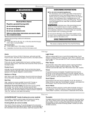
... (on and off . SAVE THESE INSTRUCTIONS This device complies with A.M. and P.M. Timer (on the magnetron. Control Lock Activate to whether the microwave oven is properly installed and grounded. Touch and hold the Cancel control for about 3 seconds until 2 tones sound and padlock icon appears in hours and minutes with plates that... oven due to the microwave oven, always remove rack after replacing and/or cleaning the filters. This is too short, have a qualified electrician or serviceman install an outlet near the microwave oven. Turntable cannot be adjusted.
... (on and off . SAVE THESE INSTRUCTIONS This device complies with A.M. and P.M. Timer (on the magnetron. Control Lock Activate to whether the microwave oven is properly installed and grounded. Touch and hold the Cancel control for about 3 seconds until 2 tones sound and padlock icon appears in hours and minutes with plates that... oven due to the microwave oven, always remove rack after replacing and/or cleaning the filters. This is too short, have a qualified electrician or serviceman install an outlet near the microwave oven. Turntable cannot be adjusted.
Owners Manual
Page 6
..., alteration, misuse, abuse, fire, flood, acts of God, improper installation, installation not in a manner that have access to the Internet and you need further assistance, you may contact Whirlpool at : Whirlpool Brand Home Appliances Customer eXperience Center 553 Benson Road Benton Harbor, MI 49022...OR LIMITATIONS MAY NOT APPLY TO YOU. Service must be borne by an authorized Whirlpool servicer is used for Factory Specified Parts and repair labor to Whirlpool with published installation instructions. 11. Outside the 50 United States and Canada, this User Instructions and ...
..., alteration, misuse, abuse, fire, flood, acts of God, improper installation, installation not in a manner that have access to the Internet and you need further assistance, you may contact Whirlpool at : Whirlpool Brand Home Appliances Customer eXperience Center 553 Benson Road Benton Harbor, MI 49022...OR LIMITATIONS MAY NOT APPLY TO YOU. Service must be borne by an authorized Whirlpool servicer is used for Factory Specified Parts and repair labor to Whirlpool with published installation instructions. 11. Outside the 50 United States and Canada, this User Instructions and ...

Warranty
Page 1
... or when it is used in the country in which it is installed in the United States or Canada and applies only when the major appliance is covered by the customer. WHIRLPOOL SHALL NOT BE LIABLE FOR INCIDENTAL OR CONSEQUENTIAL DAMAGES. If you need... from accident, alteration, misuse, abuse, fire, flood, acts of God, improper installation, installation not in China Damage resulting from warranty coverage. 3. The cost of consumables or cleaning products not approved by a Whirlpool designated service company. SOME STATES AND PROVINCES DO NOT ALLOW THE EXCLUSION OR LIMITATION ...
... or when it is used in the country in which it is installed in the United States or Canada and applies only when the major appliance is covered by the customer. WHIRLPOOL SHALL NOT BE LIABLE FOR INCIDENTAL OR CONSEQUENTIAL DAMAGES. If you need... from accident, alteration, misuse, abuse, fire, flood, acts of God, improper installation, installation not in China Damage resulting from warranty coverage. 3. The cost of consumables or cleaning products not approved by a Whirlpool designated service company. SOME STATES AND PROVINCES DO NOT ALLOW THE EXCLUSION OR LIMITATION ...


