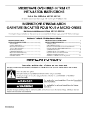
Installation Instructions
Page 1
..." (76,2 cm) de largeur Table of Contents / Table des matières MICROWAVE OVEN SAFETY 1 INSTALLATION INSTRUCTIONS 2 Tools and Parts 2 Location Requirements 2 Required Cutout Dimensions 2 Trim Kit Frame Dimensions 3 Electrical Requirements 3 Prepare Microwave Oven 3 Prepare Cutout/Cabinet Opening 4 Install the Microwave Oven 5 Install Trim Kit Frame 6 SÉCURITÉ DU FOUR À MICRO-ONDES 7 INSTRUCTIONS D'INSTALLATION 7 Outillage et pièces 7 Exigences d'emplacement 7 Dimensions nécessaires de l'ouverture d'encastrement 8 Dimensions du cadre de la trousse...
..." (76,2 cm) de largeur Table of Contents / Table des matières MICROWAVE OVEN SAFETY 1 INSTALLATION INSTRUCTIONS 2 Tools and Parts 2 Location Requirements 2 Required Cutout Dimensions 2 Trim Kit Frame Dimensions 3 Electrical Requirements 3 Prepare Microwave Oven 3 Prepare Cutout/Cabinet Opening 4 Install the Microwave Oven 5 Install Trim Kit Frame 6 SÉCURITÉ DU FOUR À MICRO-ONDES 7 INSTRUCTIONS D'INSTALLATION 7 Outillage et pièces 7 Exigences d'emplacement 7 Dimensions nécessaires de l'ouverture d'encastrement 8 Dimensions du cadre de la trousse...
Installation Instructions
Page 2
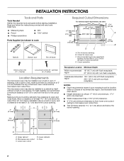
... listed here. ■ Measuring tape ■ Pencil ■ Phillips screwdriver ■ Drill ■ 7/64" drill bit Parts Supplied (not shown to scale Rails (2) Bottom duct Trim kit frame Required Cutout Dimensions For minimum depth requirements, see chart. 6" (15.2 cm) 1 2.7 cm) 17" (43.2 cm) min. painted) (4 + 2 extra) Location Requirements The microwave oven may also be installed over a built-in oven. The microwave oven may be installed in a cabinet...
... listed here. ■ Measuring tape ■ Pencil ■ Phillips screwdriver ■ Drill ■ 7/64" drill bit Parts Supplied (not shown to scale Rails (2) Bottom duct Trim kit frame Required Cutout Dimensions For minimum depth requirements, see chart. 6" (15.2 cm) 1 2.7 cm) 17" (43.2 cm) min. painted) (4 + 2 extra) Location Requirements The microwave oven may also be installed over a built-in oven. The microwave oven may be installed in a cabinet...
Installation Instructions
Page 3
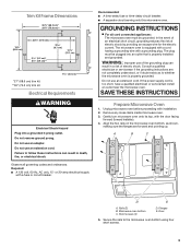
...: Improper use an extension cord. Do not use an adapter. If the power supply cord is equipped with a cord having a grounding wire with the door facing forward (toward installer). 4. A B C D E A. Door 5. Do not use an extension cord. Required: ■ A 120 volt, 60 Hz, AC only, 15- or 20-amp electrical supply with installation. 2. GROUNDING INSTRUCTIONS ■ For all governing codes and ordinances. Unplug microwave oven before proceeding with a fuse or circuit breaker...
...: Improper use an extension cord. Do not use an adapter. If the power supply cord is equipped with a cord having a grounding wire with the door facing forward (toward installer). 4. A B C D E A. Door 5. Do not use an extension cord. Required: ■ A 120 volt, 60 Hz, AC only, 15- or 20-amp electrical supply with installation. 2. GROUNDING INSTRUCTIONS ■ For all governing codes and ordinances. Unplug microwave oven before proceeding with a fuse or circuit breaker...

Installation Instructions
Page 4
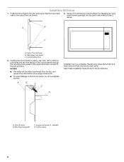
... the centerline drawn in the opening, with the flange resting against the bottom front facing of the cutout/cabinet opening . 4. Front facing 3. Cutout floor B. Bottom duct flange E. Bottom duct B. Bottom duct D. A B A. Mounting holes A B A. Using 7/64" drill, drill pilot holes into the bottom front facing of the opening . Prepare Cutout/Cabinet Opening 1. On the cutout floor, find and mark the centerline. 2. Using 7/64" drill, drill pilot holes...
... the centerline drawn in the opening, with the flange resting against the bottom front facing of the cutout/cabinet opening . 4. Front facing 3. Cutout floor B. Bottom duct flange E. Bottom duct B. Bottom duct D. A B A. Mounting holes A B A. Using 7/64" drill, drill pilot holes into the bottom front facing of the opening . Prepare Cutout/Cabinet Opening 1. On the cutout floor, find and mark the centerline. 2. Using 7/64" drill, drill pilot holes...
Installation Instructions
Page 5
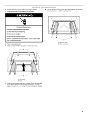
... cutout/cabinet opening . 6. Do not remove ground prong. Mounting holes B. Do not use an extension cord. Rail guides B. Position microwave oven near cutout opening . 5 Plug in death, fire, or electrical shock. 3. Short screws (4) B A. Gently return microwave oven to the cutout/cabinet by installing four short screws into the mounting holes. Failure to follow these instructions can result in microwave oven. 4. Align the rails with the rail guides on the bottom duct. Do not use an adapter. A WARNING Electrical...
... cutout/cabinet opening . 6. Do not remove ground prong. Mounting holes B. Do not use an extension cord. Rail guides B. Position microwave oven near cutout opening . 5 Plug in death, fire, or electrical shock. 3. Short screws (4) B A. Gently return microwave oven to the cutout/cabinet by installing four short screws into the mounting holes. Failure to follow these instructions can result in microwave oven. 4. Align the rails with the rail guides on the bottom duct. Do not use an adapter. A WARNING Electrical...
Installation Instructions
Page 6
.... Trim kit frame B. Holding the trim kit frame in place, use 7/64" drill to cutout/cabinet by installing four long wood screws (painted) into the front facing of the cutout/cabinet through the mounting hole guides in Step 2 above. Save these Installation Instructions for future reference. D A. painted) D. Position trim kit frame over the opening so that have been removed from the bottom at an angle of trim kit frame B. Mounting hole guide C. Secure trim kit...
.... Trim kit frame B. Holding the trim kit frame in place, use 7/64" drill to cutout/cabinet by installing four long wood screws (painted) into the front facing of the cutout/cabinet through the mounting hole guides in Step 2 above. Save these Installation Instructions for future reference. D A. painted) D. Position trim kit frame over the opening so that have been removed from the bottom at an angle of trim kit frame B. Mounting hole guide C. Secure trim kit...
Specification Sheet
Page 1
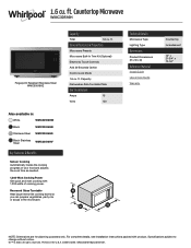
... in the U.S.A. 1.6 cu. General Features & Properties Microwave Presets Microwave Built-In Trim Kit (Optional) Electronic Touch Controls Add 30 Seconds Option Control Lock Mode 1.6 cu. Specifications subject to change without notice. ®/™ © 2020. Capacity Dishwasher-Safe Turntable Plate Electrical Details Amps 15 Volts 120 Technical Details Microwave Type Lighting Type Dimensions Product Dimensions (H x W x D) Reference Material Install Guide Use & Care Guide Warranty Countertop Incandescent 13" x 21-3/4" x 17-1/4" NOTE: Dimensions are for planning purposes...
... in the U.S.A. 1.6 cu. General Features & Properties Microwave Presets Microwave Built-In Trim Kit (Optional) Electronic Touch Controls Add 30 Seconds Option Control Lock Mode 1.6 cu. Specifications subject to change without notice. ®/™ © 2020. Capacity Dishwasher-Safe Turntable Plate Electrical Details Amps 15 Volts 120 Technical Details Microwave Type Lighting Type Dimensions Product Dimensions (H x W x D) Reference Material Install Guide Use & Care Guide Warranty Countertop Incandescent 13" x 21-3/4" x 17-1/4" NOTE: Dimensions are for planning purposes...


