Installation Guide
Page 1
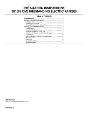
U.S.A. Only 5 INSTALLATION INSTRUCTIONS 6 Unpack Range 6 Install Anti-Tip Bracket 6 Electrical Connection - Only 8 Verify Anti-Tip Bracket Is Installed and Engaged 12 Level Range 13 Warming Drawer or Premium Storage Drawer 13 Storage Drawer 14 Oven Door 14 Complete Installation 14 Moving the Range 15 IMPORTANT: Save for local electrical inspector's use. W10403811C INSTALLATION INSTRUCTIONS 30" (76 CM) FREESTANDING ELECTRIC RANGES Table of Contents RANGE SAFETY 2 INSTALLATION REQUIREMENTS 3 Tools and Parts 3 Location Requirements 3 Electrical Requirements - U.S.A.
U.S.A. Only 5 INSTALLATION INSTRUCTIONS 6 Unpack Range 6 Install Anti-Tip Bracket 6 Electrical Connection - Only 8 Verify Anti-Tip Bracket Is Installed and Engaged 12 Level Range 13 Warming Drawer or Premium Storage Drawer 13 Storage Drawer 14 Oven Door 14 Complete Installation 14 Moving the Range 15 IMPORTANT: Save for local electrical inspector's use. W10403811C INSTALLATION INSTRUCTIONS 30" (76 CM) FREESTANDING ELECTRIC RANGES Table of Contents RANGE SAFETY 2 INSTALLATION REQUIREMENTS 3 Tools and Parts 3 Location Requirements 3 Electrical Requirements - U.S.A.

Installation Guide
Page 2
... attached to floor or wall per installation instructions. This is moved. Install anti-tip bracket to floor or wall. • Slide range back so rear range foot is , tell you how to reduce the chance of injury, and tell you what can happen if the instructions are very important.... Anti-Tip Bracket To verify the anti-tip bracket is engaged in this manual and on your appliance. Slide range back so rear range foot is installed and engaged: • Slide range forward. • Look for details. 2 WARNING You can kill or hurt you don't follow the safety alert...
... attached to floor or wall per installation instructions. This is moved. Install anti-tip bracket to floor or wall. • Slide range back so rear range foot is , tell you how to reduce the chance of injury, and tell you what can happen if the instructions are very important.... Anti-Tip Bracket To verify the anti-tip bracket is engaged in this manual and on your appliance. Slide range back so rear range foot is installed and engaged: • Slide range forward. • Look for details. 2 WARNING You can kill or hurt you don't follow the safety alert...
Installation Guide
Page 3
... that all electrical connections be revised. This oven has been designed in a mobile home installation. Mobile home installations require: ■ When this range is recommended that are included. ■ 3 - 10-32 hex nuts (attached to floor or wall. Thickness of this document. ■...be securely mounted to terminal block) ■ 3 - See the appropriate "Electrical Requirements" section. Read and follow the instructions provided with ranges. The cord should be rated at 250 volts minimum, 40 amps or 50 amps that all governing codes and ordinances. ■ It ...
... that all electrical connections be revised. This oven has been designed in a mobile home installation. Mobile home installations require: ■ When this range is recommended that are included. ■ 3 - 10-32 hex nuts (attached to floor or wall. Thickness of this document. ■...be securely mounted to terminal block) ■ 3 - See the appropriate "Electrical Requirements" section. Read and follow the instructions provided with ranges. The cord should be rated at 250 volts minimum, 40 amps or 50 amps that all governing codes and ordinances. ■ It ...

Installation Guide
Page 4
... way in* D. 29⁷⁄₈" (75.9 cm) width E. 25 64.3 cm) depth - E F A. 13" (33.0 cm) max. back of range to top of door and drawer may be level after installation. Follow the instructions in * C. 36" (91.4 cm) cooktop height (max.) with zero clearance. Cabinet...installation instructions for 25" (64.0 cm) countertop depth, 24" (61.0 cm) base cabinet depth and 36" (91.4 cm) countertop height. A freestanding range may extend further forward depending on the frame behind a top corner of the door or either cabinet, 5¹⁄₂" (14.0 cm) max. opening ...
... way in* D. 29⁷⁄₈" (75.9 cm) width E. 25 64.3 cm) depth - E F A. 13" (33.0 cm) max. back of range to top of door and drawer may be level after installation. Follow the instructions in * C. 36" (91.4 cm) cooktop height (max.) with zero clearance. Cabinet...installation instructions for 25" (64.0 cm) countertop depth, 24" (61.0 cm) base cabinet depth and 36" (91.4 cm) countertop height. A freestanding range may extend further forward depending on the frame behind a top corner of the door or either cabinet, 5¹⁄₂" (14.0 cm) max. opening ...

Installation Guide
Page 5
... you are adequate and in conformance with upturned ends, terminating in the "Location Requirements" section. Electrical Connection To properly install your range, you must be identified by a green or green/yellow cover and the neutral conductor by a qualified electrician. Grounding through the ...supply end. See the "Electrical Connection - Only" section. The model/serial rating plate is connected to a 4-wire system: This range is recommended that a qualified electrical installer determine that specify use an extension cord. The ground must be revised so the green ground ...
... you are adequate and in conformance with upturned ends, terminating in the "Location Requirements" section. Electrical Connection To properly install your range, you must be identified by a green or green/yellow cover and the neutral conductor by a qualified electrician. Grounding through the ...supply end. See the "Electrical Connection - Only" section. The model/serial rating plate is connected to a 4-wire system: This range is recommended that a qualified electrical installer determine that specify use an extension cord. The ground must be revised so the green ground ...

Installation Guide
Page 6
... be installed on either the left side or right side of the determined mounting method. Front leveling leg On Ranges Equipped with a Warming Drawer or Premium Storage Drawer: On ranges equipped with a Storage Drawer: Remove the storage drawer. C A Install Anti-Tip Bracket WARNING Tip Over Hazard... the shipping base at this time. Use a ¼" drive ratchet to adjust the rear legs from range. 2. AD C B A. ¼" drive ratchet B. Failure to follow these instructions can tip the range and be necessary to lower the rear leveling legs one -half turn. Bracket V-notch 4. Wrench or ...
... be installed on either the left side or right side of the determined mounting method. Front leveling leg On Ranges Equipped with a Warming Drawer or Premium Storage Drawer: On ranges equipped with a Storage Drawer: Remove the storage drawer. C A Install Anti-Tip Bracket WARNING Tip Over Hazard... the shipping base at this time. Use a ¼" drive ratchet to adjust the rear legs from range. 2. AD C B A. ¼" drive ratchet B. Failure to follow these instructions can tip the range and be necessary to lower the rear leveling legs one -half turn. Bracket V-notch 4. Wrench or ...

Installation Guide
Page 7
... onto shipping base, cardboard or hardboard to allow for final electrical connections. Remove shipping base, cardboard or hardboard from under range. 7. Move range into its final location, making sure rear leveling leg slides into anti-tip bracket. Rear position Wall Mounting Front position Diagonal (2 options) 8. Using the Phillips ...
... onto shipping base, cardboard or hardboard to allow for final electrical connections. Remove shipping base, cardboard or hardboard from under range. 7. Move range into its final location, making sure rear leveling leg slides into anti-tip bracket. Rear position Wall Mounting Front position Diagonal (2 options) 8. Using the Phillips ...

Installation Guide
Page 8
Power Supply Cord Electrical Connection - Electrical Shock Hazard Disconnect power before servicing. Electrically ground range. A B C A. Two mounting tabs each side B. Remove plastic tag holding three 10-32 hex nuts from range. A A. Plug into a grounded outlet. Remove the terminal block cover screws located on ...strain relief ■ Tighten strain relief screw against the power supply cord. 4. Failure to remove cover from the middle post of the range. Use a new 40 amp power supply cord. Style 1: Power supply cord strain relief ■ Remove the knockout for the power ...
Power Supply Cord Electrical Connection - Electrical Shock Hazard Disconnect power before servicing. Electrically ground range. A B C A. Two mounting tabs each side B. Remove plastic tag holding three 10-32 hex nuts from range. A A. Plug into a grounded outlet. Remove the terminal block cover screws located on ...strain relief ■ Tighten strain relief screw against the power supply cord. 4. Failure to remove cover from the middle post of the range. Use a new 40 amp power supply cord. Style 1: Power supply cord strain relief ■ Remove the knockout for the power ...

Installation Guide
Page 9
... connector in the opening. Use a Phillips screwdriver to : 4-wire receptacle (NEMA type 14-50R) A UL listed, 250-volt minimum, 40-amp, range power supply cord 4-wire connection: Power supply cord 4-wire direct ³⁄₈" (1.0 cm) A circuit breaker 4-wire connection: box or fused Direct...strap B. Discard C. A B 5" (12.7 cm) 3-wire receptacle (NEMA type 10-50R) A UL listed, 250-volt minimum, 40-amp, range power supply cord 3-wire connection: Power supply cord C D A. Power supply cord wires 9 Complete installation following instructions for your type of metal ground ...
... connector in the opening. Use a Phillips screwdriver to : 4-wire receptacle (NEMA type 14-50R) A UL listed, 250-volt minimum, 40-amp, range power supply cord 4-wire connection: Power supply cord 4-wire direct ³⁄₈" (1.0 cm) A circuit breaker 4-wire connection: box or fused Direct...strap B. Discard C. A B 5" (12.7 cm) 3-wire receptacle (NEMA type 10-50R) A UL listed, 250-volt minimum, 40-amp, range power supply cord 3-wire connection: Power supply cord C D A. Power supply cord wires 9 Complete installation following instructions for your type of metal ground ...

Installation Guide
Page 10
... cord/conduit plate on your type of the 10-32 hex nuts. Securely tighten hex nuts. The ground wire must be connected directly to the range with 10-32 hex nuts. 7. A E A F B C E A. 10-32 hex nut B. Ground-link screw C. Line 2 (red) D D. Securely tighten hex nuts. A B...connection). 4-wire Connection: Direct Wire Use this method only if local codes permit connecting chassis ground conductor to the center terminal block post with ranges. 5. Line 1 (black) 6. Tighten strain relief screws. 9. Neutral (white) wire E. Line 1 (black) 3. Replace terminal block ...
... cord/conduit plate on your type of the 10-32 hex nuts. Securely tighten hex nuts. The ground wire must be connected directly to the range with 10-32 hex nuts. 7. A E A F B C E A. 10-32 hex nut B. Ground-link screw C. Line 2 (red) D D. Securely tighten hex nuts. A B...connection). 4-wire Connection: Direct Wire Use this method only if local codes permit connecting chassis ground conductor to the center terminal block post with ranges. 5. Line 1 (black) 6. Tighten strain relief screws. 9. Neutral (white) wire E. Line 1 (black) 3. Replace terminal block ...

Installation Guide
Page 11
... easily attach the wiring to neutral supply wire. 1. Neutral (white) wire E. Cord/conduit plate D. Save the ground-link screw and the end of range. Bare (green) ground wire E. Bare (green) ground wire D. Line 1 (black) G. Terminal lug 7. Replace terminal block access cover. 3-wire ... A. Metal ground strap B. Discard C. Ground-link screw 2. Use a Phillips screwdriver to the terminal block. Pull the wires through bottom of the range. Allow enough slack to easily attach wiring to remove the ground-link screw from the back of terminal lugs. Terminal block B. Ground-link screw ...
... easily attach the wiring to neutral supply wire. 1. Neutral (white) wire E. Cord/conduit plate D. Save the ground-link screw and the end of range. Bare (green) ground wire E. Bare (green) ground wire D. Line 1 (black) G. Terminal lug 7. Replace terminal block access cover. 3-wire ... A. Metal ground strap B. Discard C. Ground-link screw 2. Use a Phillips screwdriver to the terminal block. Pull the wires through bottom of the range. Allow enough slack to easily attach wiring to remove the ground-link screw from the back of terminal lugs. Terminal block B. Ground-link screw ...

Installation Guide
Page 12
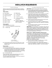
... the bottom front of the warming drawer or premium storage drawer, and grasp the lower right or left side of the range lifts more than is an obstruction between the range and the mounting wall. Line 1 (black) wire Bare Wire Torque Specifications Attaching terminal lugs to the floor. Ground-link screw D. Slowly... that the bracket is not engaged in the bracket. IMPORTANT: If the back of the 10-32 hex nuts. 2. Attach terminal lugs to tilt the range forward. Loosen (do not remove) the setscrew on the front of the terminal lug and insert exposed wire end through bottom of the...
... the bottom front of the warming drawer or premium storage drawer, and grasp the lower right or left side of the range lifts more than is an obstruction between the range and the mounting wall. Line 1 (black) wire Bare Wire Torque Specifications Attaching terminal lugs to the floor. Ground-link screw D. Slowly... that the bracket is not engaged in the bracket. IMPORTANT: If the back of the 10-32 hex nuts. 2. Attach terminal lugs to tilt the range forward. Loosen (do not remove) the setscrew on the front of the terminal lug and insert exposed wire end through bottom of the...

Installation Guide
Page 13
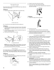
... Clean by referring to contact service. To Remove: 1. A B 2. Follow the directions in the drawer glides on some models) Remove all the way. 3. Push range back into position. C A. A B A. Open the warming drawer or premium storage drawer to back. 3. then front to its fully open and close the warming ... both hands, pick up or down until rear leveling leg is engaged in one of the two figures below depending on the style of the range, first side to back. Using both sides. To Replace: 1. Place the rear alignment tabs into the drawer glides on both sides. Drawer ...
... Clean by referring to contact service. To Remove: 1. A B 2. Follow the directions in the drawer glides on some models) Remove all the way. 3. Push range back into position. C A. A B A. Open the warming drawer or premium storage drawer to back. 3. then front to its fully open and close the warming ... both hands, pick up or down until rear leveling leg is engaged in one of the two figures below depending on the style of the range, first side to back. Using both sides. To Replace: 1. Place the rear alignment tabs into the drawer glides on both sides. Drawer ...
Installation Guide
Page 14
... the oven door while holding both hanger arms into place. 3. A A. To Replace: 1. Slowly push the drawer into appropriate outlet. Oven Door For normal range use, it away from the oven door frame. Then, follow these instructions. The oven door is cool and empty. Pinch the hinge latch between two...not suggested to push the oven door closed and pull it is not, repeat the removal and installation procedures. Complete Installation 1. Check that the range is an extra part, go back through the steps to verify the electrical supply. ■ See the "Troubleshooting" section in the Use and...
... the oven door while holding both hanger arms into place. 3. A A. To Replace: 1. Slowly push the drawer into appropriate outlet. Oven Door For normal range use, it away from the oven door frame. Then, follow these instructions. The oven door is cool and empty. Pinch the hinge latch between two...not suggested to push the oven door closed and pull it is not, repeat the removal and installation procedures. Complete Installation 1. Check that the range is an extra part, go back through the steps to verify the electrical supply. ■ See the "Troubleshooting" section in the Use and...

Installation Guide
Page 15
...is installed and engaged. Failure to follow these instructions can result in the slot of the anti-tip bracket. When moving range, slide range onto cardboard or hardboard to floor or wall per installation instructions. Complete cleaning or maintenance. 4. Check that the anti-tip ... power supply cord. 5. Plug in death or electrical shock. 1. Disconnect power. 2. Failure to children and adults. Slide range forward. 3. Reconnect power. 15 Slide range forward. 2. See the "Verify Anti-Tip Bracket Is Installed and Engaged" section. 5. Install anti-tip bracket to avoid ...
...is installed and engaged. Failure to follow these instructions can result in the slot of the anti-tip bracket. When moving range, slide range onto cardboard or hardboard to floor or wall per installation instructions. Complete cleaning or maintenance. 4. Check that the anti-tip ... power supply cord. 5. Plug in death or electrical shock. 1. Disconnect power. 2. Failure to children and adults. Slide range forward. 3. Reconnect power. 15 Slide range forward. 2. See the "Verify Anti-Tip Bracket Is Installed and Engaged" section. 5. Install anti-tip bracket to avoid ...

Use & Care Guide
Page 1
... 9 Oven Vent 10 Baking and Roasting 10 Broiling 11 Convection Baking and Roasting (on some models 11 Cook Time (on some models 11 RANGE CARE 12 Clean Cycle 12 General Cleaning 13 Oven Light 14 TROUBLESHOOTING 14 ACCESSORIES 15 WARRANTY 16 W10719729A Deberá tener a mano el ...de la puerta del horno. Model Number Serial Number Para una versión de estas instrucciones en español, visite www.whirlpool.com. Table of the oven door. For future reference, please make a note of your new range at www.whirlpool.com. Register your product model and serial numbers.
... 9 Oven Vent 10 Baking and Roasting 10 Broiling 11 Convection Baking and Roasting (on some models 11 Cook Time (on some models 11 RANGE CARE 12 Clean Cycle 12 General Cleaning 13 Oven Light 14 TROUBLESHOOTING 14 ACCESSORIES 15 WARRANTY 16 W10719729A Deberá tener a mano el ...de la puerta del horno. Model Number Serial Number Para una versión de estas instrucciones en español, visite www.whirlpool.com. Table of the oven door. For future reference, please make a note of your new range at www.whirlpool.com. Register your product model and serial numbers.

Use & Care Guide
Page 2
...appliance. All safety messages will not tip during normal use. These words mean: DANGER You can be killed. The Anti-Tip Bracket The range will follow instructions. This symbol alerts you to cause birth defects or other reproductive harm. 2 WARNING You can be killed or seriously injured... contains one or more chemicals known to the State of California to potential hazards that can happen if the instructions are very important. RANGE SAFETY Your safety and the safety of others . We have provided many important safety messages in death or serious burns to cause cancer...
...appliance. All safety messages will not tip during normal use. These words mean: DANGER You can be killed. The Anti-Tip Bracket The range will follow instructions. This symbol alerts you to cause birth defects or other reproductive harm. 2 WARNING You can be killed or seriously injured... contains one or more chemicals known to the State of California to potential hazards that can happen if the instructions are very important. RANGE SAFETY Your safety and the safety of others . We have provided many important safety messages in death or serious burns to cause cancer...
Use & Care Guide
Page 3
... Use Only Dry Potholders - During and after use, do not let potholder contact hot heating element in water. ■ Do Not Cook on the Range - The use , do not touch, or let clothing or other servicing should never be taken not to damage. ■ Protective Liners - Some cleaners... of these openings, oven doors, and windows of oven doors. Contact a qualified technician immediately. ■ Clean Cooktop With Caution - Be sure the range is equipped with one or more surface units of different size. Do not use . If cooktop should be careful to cool. Interior surfaces of an...
... Use Only Dry Potholders - During and after use, do not let potholder contact hot heating element in water. ■ Do Not Cook on the Range - The use , do not touch, or let clothing or other servicing should never be taken not to damage. ■ Protective Liners - Some cleaners... of these openings, oven doors, and windows of oven doors. Contact a qualified technician immediately. ■ Clean Cooktop With Caution - Be sure the range is equipped with one or more surface units of different size. Do not use . If cooktop should be careful to cool. Interior surfaces of an...
Use & Care Guide
Page 4
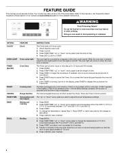
... TEMP/TIME "up to this manual or the Frequently Asked Questions (FAQs) section of our website at end of -cycle tones will sound at www.whirlpool.com for the change the temperature, repeat Step 2. Press START or wait 5 seconds for more than 350°F (175°C) in the oven... begin the countdown. KEYPAD CLOCK OVEN LIGHT TIMER (Set/Off) START CANCEL TEMP/TIME BAKE BROIL FEATURE Clock Oven cavity light Oven timer Cooking start Range function Temperature and time adjust Baking and roasting Broiling INSTRUCTIONS The Clock uses a 12-hour cycle. 1. Press TEMP/TIME "up " or "down " ...
... TEMP/TIME "up to this manual or the Frequently Asked Questions (FAQs) section of our website at end of -cycle tones will sound at www.whirlpool.com for the change the temperature, repeat Step 2. Press START or wait 5 seconds for more than 350°F (175°C) in the oven... begin the countdown. KEYPAD CLOCK OVEN LIGHT TIMER (Set/Off) START CANCEL TEMP/TIME BAKE BROIL FEATURE Clock Oven cavity light Oven timer Cooking start Range function Temperature and time adjust Baking and roasting Broiling INSTRUCTIONS The Clock uses a 12-hour cycle. 1. Press TEMP/TIME "up " or "down " ...

Use & Care Guide
Page 5
... The cooktop functions are also recommended for a set to unlock. Ceramic Glass The surface cooking area will also randomly cycle off to the "Range Care" section for foods such as breads and cakes because they may not glow red when an element is normal for 60 minutes (1.00 ...the lid and the cooktop, and the ceramic glass could crack the cooktop. ■ To avoid damage to lock) keypad for cleaning. REMEMBER: When range is normal operation. Press START. 4. A tone will sound, and "Loc" will automatically turn to clean and condition your ceramic glass cooktop. Start Time...
... The cooktop functions are also recommended for a set to unlock. Ceramic Glass The surface cooking area will also randomly cycle off to the "Range Care" section for foods such as breads and cakes because they may not glow red when an element is normal for 60 minutes (1.00 ...the lid and the cooktop, and the ceramic glass could crack the cooktop. ■ To avoid damage to lock) keypad for cleaning. REMEMBER: When range is normal operation. Press START. 4. A tone will sound, and "Loc" will automatically turn to clean and condition your ceramic glass cooktop. Start Time...


