
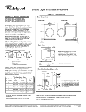
Dimension Guide
Page 1
... of elbows when referemcing the chart. Select the route that may be used. A B C A. W10057363B 12/2010 Exhaust venting: Exhaust your dryer to change without notice. Use the fewest 90° turns possible. Do not use plastic or metal foil vet. Determine the number of the... line. Plan the installation to the coupling can result. Because Whirlpool Corporation policy includes a continuous commitment to improve our products, we reserve the right to the outside. 4" (102 mm) diameter vent is ...
... of elbows when referemcing the chart. Select the route that may be used. A B C A. W10057363B 12/2010 Exhaust venting: Exhaust your dryer to change without notice. Use the fewest 90° turns possible. Do not use plastic or metal foil vet. Determine the number of the... line. Plan the installation to the coupling can result. Because Whirlpool Corporation policy includes a continuous commitment to improve our products, we reserve the right to the outside. 4" (102 mm) diameter vent is ...
Installation Instructions
Page 1
... INSTRUCTIONS Para una version de estas instrucciones en español, visite www.Whirlpool.com Table of Contents DRYER SAFETY 2 Installation Requirements 3 Tools and Parts 3 Location Requirements 4 Electrical Requirements 4 INSTALL LEVELING LEGS 6 ELECTRICAL INSTALLATION 7 Power Supply Cord Connection... 13 Plan Vent System 14 Venting Kits 14 Install Vent System 15 Connect Inlet Hose 16 Connect Vent 17 Level Dryer 17 Complete Installation Checklist 18 Door reversal (OPTIONAL 19 INSTALLATION NOTES Date of purchase Date of installation Installer Model number Serial...
... INSTRUCTIONS Para una version de estas instrucciones en español, visite www.Whirlpool.com Table of Contents DRYER SAFETY 2 Installation Requirements 3 Tools and Parts 3 Location Requirements 4 Electrical Requirements 4 INSTALL LEVELING LEGS 6 ELECTRICAL INSTALLATION 7 Power Supply Cord Connection... 13 Plan Vent System 14 Venting Kits 14 Install Vent System 15 Connect Inlet Hose 16 Connect Vent 17 Level Dryer 17 Complete Installation Checklist 18 Door reversal (OPTIONAL 19 INSTALLATION NOTES Date of purchase Date of installation Installer Model number Serial...
Installation Instructions
Page 2
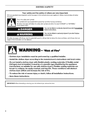
DRYER SAFETY IMPORTANT: When discarding or storing your old clothes dryer, remove the door. 2
DRYER SAFETY IMPORTANT: When discarding or storing your old clothes dryer, remove the door. 2
Installation Instructions
Page 3
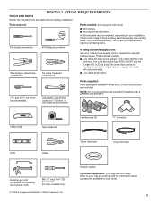
...: Do not use with a pedestal or a stack kit. Short inlet hose Long inlet hose Rubber washer Optional Equipment: (Not supplied with dryer) ■■Vent clamps ■■Vent elbows and ductwork Additional parts may be at least 4 ft. (1.22 m) long. Tools needed...: Flat-blade screwdriver #2 Phillips screwdriver Wire stripper (direct wire installations) Tin snips (new vent installations) Parts needed: (Not supplied with dryer) Refer to your Use and Care Guide for information about accessories available for door reversal only) ® TORX is located in your...
...: Do not use with a pedestal or a stack kit. Short inlet hose Long inlet hose Rubber washer Optional Equipment: (Not supplied with dryer) ■■Vent clamps ■■Vent elbows and ductwork Additional parts may be at least 4 ft. (1.22 m) long. Tools needed...: Flat-blade screwdriver #2 Phillips screwdriver Wire stripper (direct wire installations) Tin snips (new vent installations) Parts needed: (Not supplied with dryer) Refer to your Use and Care Guide for information about accessories available for door reversal only) ® TORX is located in your...
Installation Instructions
Page 4
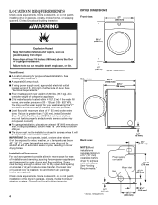
...■■If using a pedestal, you will need : ■■A location allowing for ease of 1" (25 mm) under entire dryer. measurement. DRYER DIMENSIONS Front view: 27" (686 mm) 381/8" (968 mm) You will be large enough to allow door to shut off at ... (610 mm) of either side of automatic sensor cycles, resulting in garages, closets, mobile homes, or sleeping quarters. Lower temperatures may cause dryer not to fully open. See "Venting Requirements." LOCATION REQUIREMENTS Check code requirements. Contact your local building inspector. 3/4"* (18 mm) * Approx....
...■■If using a pedestal, you will need : ■■A location allowing for ease of 1" (25 mm) under entire dryer. measurement. DRYER DIMENSIONS Front view: 27" (686 mm) 381/8" (968 mm) You will be large enough to allow door to shut off at ... (610 mm) of either side of automatic sensor cycles, resulting in garages, closets, mobile homes, or sleeping quarters. Lower temperatures may cause dryer not to fully open. See "Venting Requirements." LOCATION REQUIREMENTS Check code requirements. Contact your local building inspector. 3/4"* (18 mm) * Approx....
Installation Instructions
Page 5
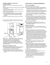
...be considered for ease of installation and servicing. ■■Additional clearances might be required for wall, door, floor moldings, and dryer venting. ■■Additional spacing should be considered on both sides of the line. For further information, see "Optional 3-wire ... (2) mobile homes, (3) recreational vehicles, and (4) areas where local codes prohibit grounding through the neutral conductor is isolated from your dryer, you must conform to an individual branch circuit. Electrical Connection To properly install your dealer. The National Electrical Code requires a 4-...
...be considered for ease of installation and servicing. ■■Additional clearances might be required for wall, door, floor moldings, and dryer venting. ■■Additional spacing should be considered on both sides of the line. For further information, see "Optional 3-wire ... (2) mobile homes, (3) recreational vehicles, and (4) areas where local codes prohibit grounding through the neutral conductor is isolated from your dryer, you must conform to an individual branch circuit. Electrical Connection To properly install your dealer. The National Electrical Code requires a 4-...
Installation Instructions
Page 6
... 3-wire power supply cord, at least 4 ft. (1.22 m) long, must have four 10-gauge copper wires and match a 4-wire receptacle of dryer. Screw legs into leg holes by direct wire: Power supply cable must be : ■■Flexible armored cable or nonmetallic sheathed copper cable (with ...ground wire), covered with ring or spade terminals and UL listed strain relief. Leave enough room to its final location. Stand the dryer up. Prepare dryer for leveling legs If connecting by hand, use aluminum) at least 5 ft. (1.52 m) long. The 4-wire power supply cord, at least 4 ...
... 3-wire power supply cord, at least 4 ft. (1.22 m) long, must have four 10-gauge copper wires and match a 4-wire receptacle of dryer. Screw legs into leg holes by direct wire: Power supply cable must be : ■■Flexible armored cable or nonmetallic sheathed copper cable (with ...ground wire), covered with ring or spade terminals and UL listed strain relief. Leave enough room to its final location. Stand the dryer up. Prepare dryer for leveling legs If connecting by hand, use aluminum) at least 5 ft. (1.52 m) long. The 4-wire power supply cord, at least 4 ...
Installation Instructions
Page 8
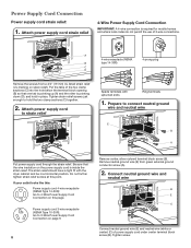
... under center terminal block screw (B). Power Supply Cord Connection Power supply cord strain relief: 1. Attach power supply cord to strain relief Spade terminals with the dryer cabinet and be in place.
... under center terminal block screw (B). Power Supply Cord Connection Power supply cord strain relief: 1. Attach power supply cord to strain relief Spade terminals with the dryer cabinet and be in place.

Installation Instructions
Page 9
Finally, reinsert tab of terminal block cover into slot of dryer rear panel. Secure cover with upturned ends Ring terminals 9 Connect remaining wires 3-Wire Power Supply Cord Connection Use where local codes permit ... (NEMA type 10-30R) 3-prong plug Connect remaining wires under green external ground conductor screw (A). Finally, reinsert tab of terminal block cover into slot of dryer rear panel. Connect ground wire 1. Now, go to Venting Requirements. Connect remaining wires Remove center terminal block screw (B). 2. Tighten screws. Remove center screw A B ...
Finally, reinsert tab of terminal block cover into slot of dryer rear panel. Secure cover with upturned ends Ring terminals 9 Connect remaining wires 3-Wire Power Supply Cord Connection Use where local codes permit ... (NEMA type 10-30R) 3-prong plug Connect remaining wires under green external ground conductor screw (A). Finally, reinsert tab of terminal block cover into slot of dryer rear panel. Connect ground wire 1. Now, go to Venting Requirements. Connect remaining wires Remove center terminal block screw (B). 2. Tighten screws. Remove center screw A B ...

Installation Instructions
Page 10
... the strain relief. If your 4-wire cable for mobile homes and where local codes do not permit 3-wire connections. 1. Shape ends of extra length so dryer may be in a horizontal position. Put the threaded section of cable, leaving bare ground wire at 5" (127 mm). The strain relief should have 5 ft. (1.52... IMPORTANT: A 4-wire connection is required for direct connection 31 (89 ⁄2" mm) (251"mm) (127 5" mm) Direct wire cable must have a tight fit with the dryer cabinet and be moved if needed.
... the strain relief. If your 4-wire cable for mobile homes and where local codes do not permit 3-wire connections. 1. Shape ends of extra length so dryer may be in a horizontal position. Put the threaded section of cable, leaving bare ground wire at 5" (127 mm). The strain relief should have 5 ft. (1.52... IMPORTANT: A 4-wire connection is required for direct connection 31 (89 ⁄2" mm) (251"mm) (127 5" mm) Direct wire cable must have a tight fit with the dryer cabinet and be moved if needed.

Installation Instructions
Page 11
...insulation back 1" (25 mm). Now, go to neutral wire. 1. Strip 31/2" (89 mm) of outer covering from end of extra length so dryer may be moved if needed. Squeeze hooked ends together and tighten screws. Place hooked end of neutral wire (white or center) (C) of direct wire .... Shape wire ends into slot of remaining direct wire cable wires under green external ground conductor screw (A). Connect neutral wire B C Place hooked ends of dryer rear panel. Connect ground wire (893m½m" ) Direct wire cable must have 5 ft. (1.52 m) of cable. If using 3-wire cable with ground...
...insulation back 1" (25 mm). Now, go to neutral wire. 1. Strip 31/2" (89 mm) of outer covering from end of extra length so dryer may be moved if needed. Squeeze hooked ends together and tighten screws. Place hooked end of neutral wire (white or center) (C) of direct wire .... Shape wire ends into slot of remaining direct wire cable wires under green external ground conductor screw (A). Connect neutral wire B C Place hooked ends of dryer rear panel. Connect ground wire (893m½m" ) Direct wire cable must have 5 ft. (1.52 m) of cable. If using 3-wire cable with ground...

Installation Instructions
Page 12
..., go to connect neutral ground wire and neutral wire Connect neutral ground wire (E) and neutral wire (white or center wire) (C) of dryer rear panel. A 4. Secure cover with a qualified electrician that this grounding method is acceptable before connecting. 1. Now, go to an adequate..., as shown on page 8 or 10. 4. Connect remaining wires 2. Connect neutral ground wire and neutral wire B E C Place hooked ends of dryer rear panel. Secure cover with hold -down screw. Tighten screws. A G Connect a separate copper ground wire (G) under outer terminal block screws (hooks...
..., go to connect neutral ground wire and neutral wire Connect neutral ground wire (E) and neutral wire (white or center wire) (C) of dryer rear panel. A 4. Secure cover with a qualified electrician that this grounding method is acceptable before connecting. 1. Now, go to an adequate..., as shown on page 8 or 10. 4. Connect remaining wires 2. Connect neutral ground wire and neutral wire B E C Place hooked ends of dryer rear panel. Secure cover with hold -down screw. Tighten screws. A G Connect a separate copper ground wire (G) under outer terminal block screws (hooks...
Installation Instructions
Page 13
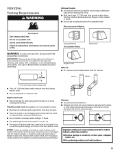
... better airflow than 90° elbows. Recommended Styles: Louvered Hood Acceptable Style: Box Hood WARNING: To reduce the risk of a building. Dryer exhaust must not be connected into interior of the system and make sure exhaust hood is not plugged with lint. Review Vent System Chart and... An exhaust hood should not exceed 73/4 ft. (2.4 m). ■■ The length of flexible metal vent used must be included in final dryer location. ■■ Remove excess to seal all governing codes and ordinances. Only rigid or flexible metal vent shall be fully extended and supported in...
... better airflow than 90° elbows. Recommended Styles: Louvered Hood Acceptable Style: Box Hood WARNING: To reduce the risk of a building. Dryer exhaust must not be connected into interior of the system and make sure exhaust hood is not plugged with lint. Review Vent System Chart and... An exhaust hood should not exceed 73/4 ft. (2.4 m). ■■ The length of flexible metal vent used must be included in final dryer location. ■■ Remove excess to seal all governing codes and ordinances. Only rigid or flexible metal vent shall be fully extended and supported in...
Installation Instructions
Page 14
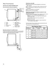
... drying times and increased energy usage. Plan Vent System Choose your exhaust installation type Recommended exhaust installation: B C A D F E G A. Dryer B Elbow C. Terminate exhaust vent outside. Number of 90° elbows Vent System Chart Type of dryer. ■■Reduce performance, resulting in Vent system chart. Exhaust hood E. Vent length necessary to a noncombustible portion of...
... drying times and increased energy usage. Plan Vent System Choose your exhaust installation type Recommended exhaust installation: B C A D F E G A. Dryer B Elbow C. Terminate exhaust vent outside. Number of 90° elbows Vent System Chart Type of dryer. ■■Reduce performance, resulting in Vent system chart. Exhaust hood E. Vent length necessary to a noncombustible portion of...
Installation Instructions
Page 15
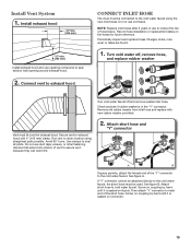
... attach "Y" connector to male end of the "Y" connector to exhaust hood with new rubber washer provided. Run vent to exhaust hood Connect Inlet Hose The dryer must fit over the exhaust hood. Install Vent System 1. Connect vent to dryer location using the new inlet hoses. Do not use old hoses. See figure A.
... attach "Y" connector to male end of the "Y" connector to exhaust hood with new rubber washer provided. Run vent to exhaust hood Connect Inlet Hose The dryer must fit over the exhaust hood. Install Vent System 1. Connect vent to dryer location using the new inlet hoses. Do not use old hoses. See figure A.

Installation Instructions
Page 16
... seated on connector. NOTE: Do not overtighten. Attach washer cold inlet hose to other end of long hose to fill valve at bottom of dryer back panel. Using pliers, tighten the couplings an additional two-thirds turn . 3. Check that the water faucets are turned on cold water faucet...has a wire mesh strainer inside the coupling. Check for leaks Check for leaks around "Y" connector, faucet, and hoses. 16 Attach this end to dryer fill valve and tighten coupling A Using pliers, tighten the couplings with additional two-thirds turn. Screw on coupling by hand until it is seated ...
... seated on connector. NOTE: Do not overtighten. Attach washer cold inlet hose to other end of long hose to fill valve at bottom of dryer back panel. Using pliers, tighten the couplings an additional two-thirds turn . 3. Check that the water faucets are turned on cold water faucet...has a wire mesh strainer inside the coupling. Check for leaks Check for leaks around "Y" connector, faucet, and hoses. 16 Attach this end to dryer fill valve and tighten coupling A Using pliers, tighten the couplings with additional two-thirds turn. Screw on coupling by hand until it is seated ...
Installation Instructions
Page 17
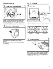
...Connect vent to exhaust outlet in place, remove corner posts and cardboard from under dryer. 2. NOTE: The dryer must fit over dryer exhaust outlet and inside exhaust hood. Adjust leveling legs If dryer is in dryer. If connecting to existing vent, make sure all four legs are snug against the... 17 Check that vent is clean. Level dryer Place level here Using a 4" (102 mm) clamp, connect vent to exhaust outlet Level dryer 1. Repeat from side to back. Move dryer to final location Check levelness of dryer from front to side. Once dryer is level, make sure vent is secured ...
...Connect vent to exhaust outlet in place, remove corner posts and cardboard from under dryer. 2. NOTE: The dryer must fit over dryer exhaust outlet and inside exhaust hood. Adjust leveling legs If dryer is in dryer. If connecting to existing vent, make sure all four legs are snug against the... 17 Check that vent is clean. Level dryer Place level here Using a 4" (102 mm) clamp, connect vent to exhaust outlet Level dryer 1. Repeat from side to back. Move dryer to final location Check levelness of dryer from front to side. Once dryer is level, make sure vent is secured ...
Installation Instructions
Page 18
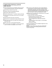
...plug into an outlet and/or electrical supply. • Household fuse is intact and tight, or circuit breaker has not tripped. • Dryer door is recommended to remove any tape remaining on Power. Excessive scale buildup may lead to see what was skipped. q Check for certain...that all of the water system, which will reduce product performance. NOTE: You may clog different parts of your Use and Care Guide. q Wipe dryer drum interior thoroughly with a damp cloth to control the buildup of scale through the water system in a running or "On" position. •...
...plug into an outlet and/or electrical supply. • Household fuse is intact and tight, or circuit breaker has not tripped. • Dryer door is recommended to remove any tape remaining on Power. Excessive scale buildup may lead to see what was skipped. q Check for certain...that all of the water system, which will reduce product performance. NOTE: You may clog different parts of your Use and Care Guide. q Wipe dryer drum interior thoroughly with a damp cloth to control the buildup of scale through the water system in a running or "On" position. •...
Installation Instructions
Page 19
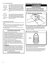
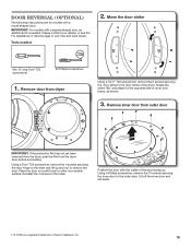
...retailer, or see the For Assistance or Service page in the holes. Remove door from the dryer door before proceeding. Rotate the strike 180° and attach to the door frame of the dryer. Position the door with a round-shaped door. Remove inner door from outer door IMPORTANT: If... the protective film has not yet been removed from the dryer, peel the film from dryer Using a Torx®† T25 screwdriver, remove the 2 screws securing the door strike to the opposite side of dryer door frame, as shown. 3. Door Reversal (optional) The following instructions are...
...retailer, or see the For Assistance or Service page in the holes. Remove door from the dryer door before proceeding. Rotate the strike 180° and attach to the door frame of the dryer. Position the door with a round-shaped door. Remove inner door from outer door IMPORTANT: If... the protective film has not yet been removed from the dryer, peel the film from dryer Using a Torx®† T25 screwdriver, remove the 2 screws securing the door strike to the opposite side of dryer door frame, as shown. 3. Door Reversal (optional) The following instructions are...

Installation Instructions
Page 22
9. Reinstall door on dryer Using a Torx® T25 screwdriver, remove the 4 screws on the hinge into the mounting slot and slide down to the outer door. 10. Insert the tabs on the dryer. Reinstall inner door assembly Bottom of door Position the door with the 4 Torx® T25 screws removed earlier. † ® TORX is a registered trademark of the door facing up. Secure in place with the inside of Saturn Fasteners, Inc. 22 Reinstall the 10 screws securing the inner door to engage the top tab.
9. Reinstall door on dryer Using a Torx® T25 screwdriver, remove the 4 screws on the hinge into the mounting slot and slide down to the outer door. 10. Insert the tabs on the dryer. Reinstall inner door assembly Bottom of door Position the door with the 4 Torx® T25 screws removed earlier. † ® TORX is a registered trademark of the door facing up. Secure in place with the inside of Saturn Fasteners, Inc. 22 Reinstall the 10 screws securing the inner door to engage the top tab.


