Quick Reference Sheet
Page 1
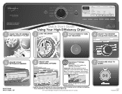
...on model. 1 CLEAN THE LINT SCREEN AND HybridCare™ FILTER* Quick Start Guide Using Your High Efficiency Dryer 2 LOAD THE DRYER 3 TOUCH POWER TO TURN ON THE DRYER 4 SELECT THE DESIRED CYCLE FOR YOUR LOAD 5 ADJUST CYCLE SETTINGS IF DESIRED 6 SELECT ANY ADDITIONAL OPTIONS ...HybridCare™ Energy Options Speed: Select this option to blend between cycle time and energy savings. SP NOTE: Energy savings may vary depending on . ®/™ ©2015 Whirlpool...
...on model. 1 CLEAN THE LINT SCREEN AND HybridCare™ FILTER* Quick Start Guide Using Your High Efficiency Dryer 2 LOAD THE DRYER 3 TOUCH POWER TO TURN ON THE DRYER 4 SELECT THE DESIRED CYCLE FOR YOUR LOAD 5 ADJUST CYCLE SETTINGS IF DESIRED 6 SELECT ANY ADDITIONAL OPTIONS ...HybridCare™ Energy Options Speed: Select this option to blend between cycle time and energy savings. SP NOTE: Energy savings may vary depending on . ®/™ ©2015 Whirlpool...
Installation Guide
Page 2
Do not contact the thermostat bracket while the appliance is energized. 2 Service Personnel - Dryer Safety Certain internal parts are intentionally not grounded and may present a risk of electric shock only during servicing.
Do not contact the thermostat bracket while the appliance is energized. 2 Service Personnel - Dryer Safety Certain internal parts are intentionally not grounded and may present a risk of electric shock only during servicing.

Installation Guide
Page 3
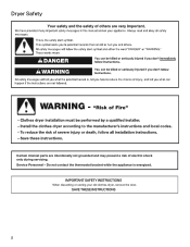
...mm) or hex-head socket wrench Cable ties (2) Parts package is located in ring terminals or spade terminals with dryer) Refer to the dryer must end in dryer drum. The wires that connect to your Use and Care Guide for information about accessories available for use leveling legs... power supply cord, rated 120/240 volt minimum. If using a power supply cord: Use a UL-listed power supply cord kit marked for your dryer. Tools needed: Parts supplied: Flat-blade screwdriver #2 Phillips screwdriver Leveling legs (4) 6' (1829 mm) drain hose with couplers Wire stripper (direct wire...
...mm) or hex-head socket wrench Cable ties (2) Parts package is located in ring terminals or spade terminals with dryer) Refer to the dryer must end in dryer drum. The wires that connect to your Use and Care Guide for information about accessories available for use leveling legs... power supply cord, rated 120/240 volt minimum. If using a power supply cord: Use a UL-listed power supply cord kit marked for your dryer. Tools needed: Parts supplied: Flat-blade screwdriver #2 Phillips screwdriver Leveling legs (4) 6' (1829 mm) drain hose with couplers Wire stripper (direct wire...

Installation Guide
Page 4
...as possible and make sure drain hose is greater than 1" (25 mm), water could run out from front of dryer. ■■The dryer must support dryer weight of 1" (25 mm) under entire dryer. If not level, clothes may not tumble properly and automatic sensor cycles may not operate correctly. ■■...) 31 " min. (806 mm) You will be installed or stored in an area where it will be exposed to shut off at end of dryer. Install Extended Dryer Feet Kit, Part Number 279810. Lower temperatures may not operate properly. 383/4" Min. (984 mm) 39" Max. (990 mm) 4 If using a pedestal,...
...as possible and make sure drain hose is greater than 1" (25 mm), water could run out from front of dryer. ■■The dryer must support dryer weight of 1" (25 mm) under entire dryer. If not level, clothes may not tumble properly and automatic sensor cycles may not operate correctly. ■■...) 31 " min. (806 mm) You will be installed or stored in an area where it will be exposed to shut off at end of dryer. Install Extended Dryer Feet Kit, Part Number 279810. Lower temperatures may not operate properly. 383/4" Min. (984 mm) 39" Max. (990 mm) 4 If using a pedestal,...
Installation Guide
Page 5
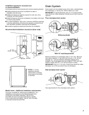
... 3" (76 mm) 1" (25 mm) 1" (25 mm) With 15" matching pedestal Minimum diameter for mobile home installations. Recommended installation clearances (dryer only): Drain System Drain system can be at least 30" (762 mm) high; IMPORTANT: To avoid siphoning, only 4.5" (114 mm) of the... secure drain hose with equivalent ventilation openings are required. Minimum carry-away capacity: 17 gal. (64 L) per minute. Additional installation requirements: This dryer is suitable for a standpipe drain: 2" (51 mm). Louvered doors with cable tie. Floor standpipe drain system 4.5" (114 mm) max. 54...
... 3" (76 mm) 1" (25 mm) 1" (25 mm) With 15" matching pedestal Minimum diameter for mobile home installations. Recommended installation clearances (dryer only): Drain System Drain system can be at least 30" (762 mm) high; IMPORTANT: To avoid siphoning, only 4.5" (114 mm) of the... secure drain hose with equivalent ventilation openings are required. Minimum carry-away capacity: 17 gal. (64 L) per minute. Additional installation requirements: This dryer is suitable for a standpipe drain: 2" (51 mm). Louvered doors with cable tie. Floor standpipe drain system 4.5" (114 mm) max. 54...

Installation Guide
Page 6
...External Ground 3-wire connection" section. ■■A 4-wire power supply connection must be used , it here. ■■This dryer is manufactured ready to avoid siphoning. The ground wire (ground 4-wire receptacle conductor) may be obtained from the external ground connector (...-circuit installations after 1996, and all local codes and ordinances. Grounding through the neutral is prohibited for homes built after 1996, dryer circuits involved in remodeling after 1996, (2) mobile homes, (3) recreational vehicles, and (4) areas where local codes prohibit grounding through ...
...External Ground 3-wire connection" section. ■■A 4-wire power supply connection must be used , it here. ■■This dryer is manufactured ready to avoid siphoning. The ground wire (ground 4-wire receptacle conductor) may be obtained from the external ground connector (...-circuit installations after 1996, and all local codes and ordinances. Grounding through the neutral is prohibited for homes built after 1996, dryer circuits involved in remodeling after 1996, (2) mobile homes, (3) recreational vehicles, and (4) areas where local codes prohibit grounding through ...
Installation Guide
Page 7
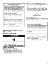
... Blvd., Toronto, ON M9W 1R3 CANADA. 7 A time-delay fuse or circuit breaker is properly installed and grounded in conformance with the dryer: if it will reduce the risk of electric shock by providing a path of malfunction or breakdown, grounding will not t the outlet, ...quali ed electrician or service representative or personnel if you use an extension cord. GROUNDING INSTRUCTIONS I For a grounded, cord-connected dryer: This dryer must be sure that the electrical connection is properly grounded. In the event of least resistance for electric current. The plug must...
... Blvd., Toronto, ON M9W 1R3 CANADA. 7 A time-delay fuse or circuit breaker is properly installed and grounded in conformance with the dryer: if it will reduce the risk of electric shock by providing a path of malfunction or breakdown, grounding will not t the outlet, ...quali ed electrician or service representative or personnel if you use an extension cord. GROUNDING INSTRUCTIONS I For a grounded, cord-connected dryer: This dryer must be sure that the electrical connection is properly grounded. In the event of least resistance for electric current. The plug must...

Installation Guide
Page 8
... a power supply cord or a direct wire connection. 2. NOTE: If local codes do not permit connection of cardboard from bottom of dryer. Now stand the dryer on cardboard. To avoid damaging floor, use a large flat piece of a cabinet-ground conductor to neutral wire, go to "Optional External..., screw leveling legs into leg holes until it is close to "Direct Wire Connection." This connection may drain when dryer is approximately 1/2" (13 mm) from dryer carton; Prepare dryer for leveling legs Electric Installation - Go to "Power Supply Cord Connection." place under entire back edge of...
... a power supply cord or a direct wire connection. 2. NOTE: If local codes do not permit connection of cardboard from bottom of dryer. Now stand the dryer on cardboard. To avoid damaging floor, use a large flat piece of a cabinet-ground conductor to neutral wire, go to "Optional External..., screw leveling legs into leg holes until it is close to "Direct Wire Connection." This connection may drain when dryer is approximately 1/2" (13 mm) from dryer carton; Prepare dryer for leveling legs Electric Installation - Go to "Power Supply Cord Connection." place under entire back edge of...

Installation Guide
Page 9
... the power supply cord is pointing down (D), and hold the 2 clamp sections (C) together. 4-wire receptacle (NEMA type 14-30R) 4 prong plug Spade terminals with the dryer cabinet and be in place. Power supply cord 3-wire receptacle (NEMA Type 10-30R): Go to "4-Wire Power Supply Cord Connection." Attach power supply cord...
... the power supply cord is pointing down (D), and hold the 2 clamp sections (C) together. 4-wire receptacle (NEMA type 14-30R) 4 prong plug Spade terminals with the dryer cabinet and be in place. Power supply cord 3-wire receptacle (NEMA Type 10-30R): Go to "4-Wire Power Supply Cord Connection." Attach power supply cord...

Installation Guide
Page 10
... A B F Connect ground wire (F) (green or bare) of power supply cord under outer terminal block screws. Finally, reinsert tab of terminal block cover into slot of dryer rear panel. Now, go to "Connect Outlet Hose." 3-Wire Power Supply Cord Connection Use where local codes permit connecting cabinet-ground conductor to connect neutral...
... A B F Connect ground wire (F) (green or bare) of power supply cord under outer terminal block screws. Finally, reinsert tab of terminal block cover into slot of dryer rear panel. Now, go to "Connect Outlet Hose." 3-Wire Power Supply Cord Connection Use where local codes permit connecting cabinet-ground conductor to connect neutral...

Installation Guide
Page 11
... hole below the terminal block opening , screw the removable conduit connector (A) onto the strain relief threads, and tighten securely. 11 Put the threaded section of dryer rear panel. Attach direct wire strain relief Connect remaining wires under center terminal block screw (B). B C Unscrew the removable conduit connector (A) and any screws from a 3/4" (19...
... hole below the terminal block opening , screw the removable conduit connector (A) onto the strain relief threads, and tighten securely. 11 Put the threaded section of dryer rear panel. Attach direct wire strain relief Connect remaining wires under center terminal block screw (B). B C Unscrew the removable conduit connector (A) and any screws from a 3/4" (19...

Installation Guide
Page 12
Prepare to strain relief 2. A Strip 5" (127 mm) of extra length so dryer may be in a horizontal position. F Shape ends of terminal block (B). The strain relief should have 5 ft. (1.52 m) of outer covering from remaining 3 wires. Squeeze ...hooked ends together and tighten screw. (127 5" mm) 4. Connect ground wire Direct wire cable must have a tight fit with the dryer cabinet and be moved if needed. Connect neutral ground wire and neutral wire B E C Connect neutral ground wire (E) and place hooked end (hook facing right) of...
Prepare to strain relief 2. A Strip 5" (127 mm) of extra length so dryer may be in a horizontal position. F Shape ends of terminal block (B). The strain relief should have 5 ft. (1.52 m) of outer covering from remaining 3 wires. Squeeze ...hooked ends together and tighten screw. (127 5" mm) 4. Connect ground wire Direct wire cable must have a tight fit with the dryer cabinet and be moved if needed. Connect neutral ground wire and neutral wire B E C Connect neutral ground wire (E) and place hooked end (hook facing right) of...

Installation Guide
Page 13
... strain relief for 3-Wire Connection (Power Supply Cord Shown) IMPORTANT: You must have 5 ft. (1.52 m) of extra length so dryer may be moved if needed. Connect remaining wires 3. Squeeze hooked end together. Finally, reinsert tab of terminal block cover into slot of... wire. 1. Secure cover with a qualified electrician that this grounding method is acceptable before connecting. 1. Remove center screw Place hooked ends of dryer rear panel. Optional External Ground for your 3-wire cable for direct connection (251m" m) Place hooked end of neutral wire (white or center...
... strain relief for 3-Wire Connection (Power Supply Cord Shown) IMPORTANT: You must have 5 ft. (1.52 m) of extra length so dryer may be moved if needed. Connect remaining wires 3. Squeeze hooked end together. Finally, reinsert tab of terminal block cover into slot of... wire. 1. Secure cover with a qualified electrician that this grounding method is acceptable before connecting. 1. Remove center screw Place hooked ends of dryer rear panel. Optional External Ground for your 3-wire cable for direct connection (251m" m) Place hooked end of neutral wire (white or center...

Installation Guide
Page 14
...-neck fitting of the provided 6 ft. (1829 mm) drain hose to "Connect Outlet Hose." Now, go to the drain valve at the bottom of dryer rear panel. Attach hose Connect neutral ground wire (E) and neutral wire (white or center wire) (C) of remaining wires under outer terminal block screws. Tighten ...1. Tighten screw. 3. Screw on coupling by hand until it is seated on valve connector. 2. Finally, reinsert tab of terminal block cover into slot of dryer back panel. Secure drain hose to laundry tub leg, drain standpipe, or inlet hoses for wall standpipe with hold-down screw.
...-neck fitting of the provided 6 ft. (1829 mm) drain hose to "Connect Outlet Hose." Now, go to the drain valve at the bottom of dryer rear panel. Attach hose Connect neutral ground wire (E) and neutral wire (white or center wire) (C) of remaining wires under outer terminal block screws. Tighten ...1. Tighten screw. 3. Screw on coupling by hand until it is seated on valve connector. 2. Finally, reinsert tab of terminal block cover into slot of dryer back panel. Secure drain hose to laundry tub leg, drain standpipe, or inlet hoses for wall standpipe with hold-down screw.

Installation Guide
Page 15
... side to side. While running the first cycle, check that there are snug against the floor and dryer does not rock. Adjust leveling legs Not Level 4. Check for leaks If dryer is level, make sure all four legs are no leaks from front to operate correctly. Plug into a grounded 3 prong outlet Not... Level LEVEL 2. Once dryer is not level, prop up using a wood block, use wrench to adjust legs up or down, and check again for the moisture-sensing system to ...
... side to side. While running the first cycle, check that there are snug against the floor and dryer does not rock. Adjust leveling legs Not Level 4. Check for leaks If dryer is level, make sure all four legs are no leaks from front to operate correctly. Plug into a grounded 3 prong outlet Not... Level LEVEL 2. Once dryer is not level, prop up using a wood block, use wrench to adjust legs up or down, and check again for the moisture-sensing system to ...
Installation Guide
Page 16
...Timed Dry heated cycle and start of /recycle all packaging materials. Remove door from dryer IMPORTANT: If the protective film has not yet been removed from the dryer, peel the film from the dryer door before proceeding. Reinstall the 4 screws in the holes. †® ...optional) The following : • Controls are registered trademarks of your Use and Care Guide. See "Level Dryer." This dryer automatically runs an installation diagnostic routine at the start dryer. q Dispose of its first cycle. Using a T25® screwdriver, remove the 4 screws securing the door...
...Timed Dry heated cycle and start of /recycle all packaging materials. Remove door from dryer IMPORTANT: If the protective film has not yet been removed from the dryer, peel the film from the dryer door before proceeding. Reinstall the 4 screws in the holes. †® ...optional) The following : • Controls are registered trademarks of your Use and Care Guide. See "Level Dryer." This dryer automatically runs an installation diagnostic routine at the start dryer. q Dispose of its first cycle. Using a T25® screwdriver, remove the 4 screws securing the door...

Installation Guide
Page 17
A Fig. Using a Phillips screwdriver, remove the 10 screws securing the inner door to the door frame of the dryer. 2. Rotate the strike 180° and attach to the opposite side of the door facing up and off the inner door and set aside (B). B Using a ... and rotate the outer window assembly clockwise until the square notches line up with the 4 tabs on the trim ring indicated with the inside of dryer door frame as shown. 3. Remove inner door from outer door Fig. Then lift out the outer window and retainer up .
A Fig. Using a Phillips screwdriver, remove the 10 screws securing the inner door to the door frame of the dryer. 2. Rotate the strike 180° and attach to the opposite side of the door facing up and off the inner door and set aside (B). B Using a ... and rotate the outer window assembly clockwise until the square notches line up with the 4 tabs on the trim ring indicated with the inside of dryer door frame as shown. 3. Remove inner door from outer door Fig. Then lift out the outer window and retainer up .

Installation Guide
Page 19
... securing the latch plate and latch backing plate and the 5 screws holding the hinge assembly in place. 8. 7. Remove hinge and latch Latch 9. Reinstall door on dryer Using a T25® screwdriver, reinstall the latch plate, latch backing plate, and hinge assembly on the...
... securing the latch plate and latch backing plate and the 5 screws holding the hinge assembly in place. 8. 7. Remove hinge and latch Latch 9. Reinstall door on dryer Using a T25® screwdriver, reinstall the latch plate, latch backing plate, and hinge assembly on the...

Installation Guide
Page 20
...shown. Reinstall the 4 screws in place. 20 Using a Phillips screwdriver, remove the 10 screws securing the inner door to the door frame of the dryer. Lift off the inner door and set aside. 4. Remove hinge and latch Latch Using a T25® screwdriver, remove the 2 screws securing the door... strike to the outer door. Remove inner door from outer door IMPORTANT: If the protective film has not yet been removed from the dryer, peel the film from dryer 3. Hinge Using a T25® screwdriver, remove the 3 screws securing the latch plate and latch backing plate and the 5 screws ...
...shown. Reinstall the 4 screws in place. 20 Using a Phillips screwdriver, remove the 10 screws securing the inner door to the door frame of the dryer. Lift off the inner door and set aside. 4. Remove hinge and latch Latch Using a T25® screwdriver, remove the 2 screws securing the door... strike to the outer door. Remove inner door from outer door IMPORTANT: If the protective film has not yet been removed from the dryer, peel the film from dryer 3. Hinge Using a T25® screwdriver, remove the 3 screws securing the latch plate and latch backing plate and the 5 screws ...

Installation Guide
Page 21
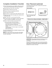
... the door. single handle 1. Reinstall inner door assembly Bottom of the door facing up and out to engage the top tab. Remove door from dryer Position the door with the 4 screws removed earlier. Reinstall the 4 screws in place with the inside of door Using a T25® screwdriver,... remove the 4 screws on opposite sides 7. Reinstall door on dryer Using a T25® screwdriver, reinstall the latch plate and latch backing plate with the 3 screws removed earlier and the hinge assembly with the 5 ...
... the door. single handle 1. Reinstall inner door assembly Bottom of the door facing up and out to engage the top tab. Remove door from dryer Position the door with the 4 screws removed earlier. Reinstall the 4 screws in place with the inside of door Using a T25® screwdriver,... remove the 4 screws on opposite sides 7. Reinstall door on dryer Using a T25® screwdriver, reinstall the latch plate and latch backing plate with the 3 screws removed earlier and the hinge assembly with the 5 ...


