Dimension Guide
Page 2
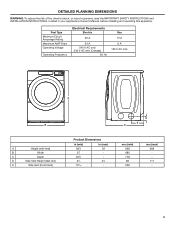
... Circuit Amperage Rating Maximum AMP Draw Operating Voltage Operating Frequency Electrical Requirements Electric 30 A 24 A 240 V AC only 230 V AC only (Canada) 60 Hz Gas 15 A 6 A 120 V AC only A B A Height (with feet) B Width C Depth D Side Vent Height (feet min) E Side Vent (from back) Product Dimensions in (min) 381∕8 27 305∕8 31∕2 103∕16 in your appliance's Owner's Manual, before installing...
... Circuit Amperage Rating Maximum AMP Draw Operating Voltage Operating Frequency Electrical Requirements Electric 30 A 24 A 240 V AC only 230 V AC only (Canada) 60 Hz Gas 15 A 6 A 120 V AC only A B A Height (with feet) B Width C Depth D Side Vent Height (feet min) E Side Vent (from back) Product Dimensions in (min) 381∕8 27 305∕8 31∕2 103∕16 in your appliance's Owner's Manual, before installing...
Owners Manual
Page 2
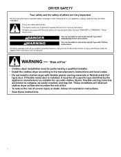
... all safety messages. Flexible venting materials are not followed. WARNING - If flexible metal duct is installed, it must be easily crushed, and trap lint. These conditions will tell you what the potential hazard is the safety alert symbol. This symbol alerts you to the manufacturer's instructions and local codes. − Do not install a clothes dryer with clothes dryers. We have provided many...
... all safety messages. Flexible venting materials are not followed. WARNING - If flexible metal duct is installed, it must be easily crushed, and trap lint. These conditions will tell you what the potential hazard is the safety alert symbol. This symbol alerts you to the manufacturer's instructions and local codes. − Do not install a clothes dryer with clothes dryers. We have provided many...
Owners Manual
Page 3
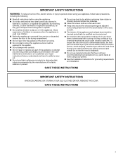
... the end of the drying cycle unless all items are quickly removed and spread out so that the heat is moving. � Do not install or store this appliance where it will be cleaned periodically by the manufacturer (e.g. SAVE THESE INSTRUCTIONS IMPORTANT SAFETY INSTRUCTIONS WHEN DISCARDING OR STORING YOUR OLD CLOTHES DRYER, REMOVE THE DOOR. parts made at home using the appliance. � Do...
... the end of the drying cycle unless all items are quickly removed and spread out so that the heat is moving. � Do not install or store this appliance where it will be cleaned periodically by the manufacturer (e.g. SAVE THESE INSTRUCTIONS IMPORTANT SAFETY INSTRUCTIONS WHEN DISCARDING OR STORING YOUR OLD CLOTHES DRYER, REMOVE THE DOOR. parts made at home using the appliance. � Do...
Owners Manual
Page 4
... subject to change. The SAID code is subject to connect your appliance prior to correct the interference by one of the FCC Rules. This device must not be guided through the steps to set up a user account and to the following two conditions: 1. Under Industry Canada regulations, this radio transmitter may cause undesired operation of a type and maximum...
... subject to change. The SAID code is subject to connect your appliance prior to correct the interference by one of the FCC Rules. This device must not be guided through the steps to set up a user account and to the following two conditions: 1. Under Industry Canada regulations, this radio transmitter may cause undesired operation of a type and maximum...
Owners Manual
Page 5
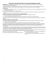
... exhaust vent: Lint should be removed every 2 years, or more frequently, if it (even after washing). This buildup can increase drying time. 2. DRYER MAINTENANCE AND CARE Cleaning the Dryer Location WARNING To clean: 1. Using a vacuum, gently remove any lint that would block the airflow for your clothes, or cause the dryer to do so can result in dryer. 5 Clean the lint screen with hot water and liquid detergent. Roll lint off the screen into place. Cleaning the Lint Screen Every load cleaning...
... exhaust vent: Lint should be removed every 2 years, or more frequently, if it (even after washing). This buildup can increase drying time. 2. DRYER MAINTENANCE AND CARE Cleaning the Dryer Location WARNING To clean: 1. Using a vacuum, gently remove any lint that would block the airflow for your clothes, or cause the dryer to do so can result in dryer. 5 Clean the lint screen with hot water and liquid detergent. Roll lint off the screen into place. Cleaning the Lint Screen Every load cleaning...
Owners Manual
Page 6
... cover. Use tape to efficiently dry laundry. Open the dryer door. Locate the light bulb cover on some models)" for an extended period of the vent system at fuse or breaker box. 2. Replace the cover and secure with a 10 W appliance bulb only. See Installation Instructions. To clean or repair venting, contact a venting specialist. Unplug dryer or disconnect power. 2. This helps to avoid flooding (due to the dryer. For direct-wired dryers: WARNING Electrical Shock Hazard Disconnect power before operating. then drain the hose...
... cover. Use tape to efficiently dry laundry. Open the dryer door. Locate the light bulb cover on some models)" for an extended period of the vent system at fuse or breaker box. 2. Replace the cover and secure with a 10 W appliance bulb only. See Installation Instructions. To clean or repair venting, contact a venting specialist. Unplug dryer or disconnect power. 2. This helps to avoid flooding (due to the dryer. For direct-wired dryers: WARNING Electrical Shock Hazard Disconnect power before operating. then drain the hose...
Owners Manual
Page 7
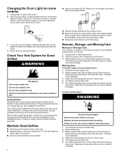
... all models): Flat-blade screwdriver Wire stripper 1/4" Nut driver Level Leveling legs (4) (Length and appearance of replacement. Gather required tools and parts before starting installation. Tools Needed for Steam Models Install and store your dryer. NOTE: Do not use leveling legs supplied with dryer if installing with any tools listed here. Parts Needed (steam models): "Y" connector Rubber washer Pliers Tape measure 2' (0.6 m) inlet hose 5' (1.52 m) inlet hose 7 Flush water pipes. INSTALLATION REQUIREMENTS Tools and Parts NOTE: Install the clothes dryer according...
... all models): Flat-blade screwdriver Wire stripper 1/4" Nut driver Level Leveling legs (4) (Length and appearance of replacement. Gather required tools and parts before starting installation. Tools Needed for Steam Models Install and store your dryer. NOTE: Do not use leveling legs supplied with dryer if installing with any tools listed here. Parts Needed (steam models): "Y" connector Rubber washer Pliers Tape measure 2' (0.6 m) inlet hose 5' (1.52 m) inlet hose 7 Flush water pipes. INSTALLATION REQUIREMENTS Tools and Parts NOTE: Install the clothes dryer according...
Owners Manual
Page 8
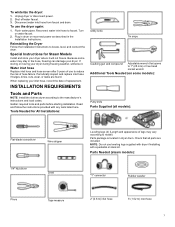
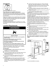
... "Electrical Requirements" and "Venting Requirements" before purchasing parts. Contact your Quick Start Guide. Recommended installation clearances (dryer only): *Recommended/Minimum spacing 8 Check code requirements. You may cause dryer not to water and/or weather. Add spacing on all sides of the dryer to fully open. Vented Models: Vent Clamps, elbows, and vent work Parts Needed (not supplied with dryer): Additional parts may not operate correctly. � For garage installation, place dryer at end of automatic sensor cycles, resulting in longer drying times. Check...
... "Electrical Requirements" and "Venting Requirements" before purchasing parts. Contact your Quick Start Guide. Recommended installation clearances (dryer only): *Recommended/Minimum spacing 8 Check code requirements. You may cause dryer not to water and/or weather. Add spacing on all sides of the dryer to fully open. Vented Models: Vent Clamps, elbows, and vent work Parts Needed (not supplied with dryer): Additional parts may not operate correctly. � For garage installation, place dryer at end of automatic sensor cycles, resulting in longer drying times. Check...
Owners Manual
Page 9
... introduce outside air into the dryer. Additional installation requirements This dryer is permanently connected to the neutral conductor (white wire) within the dryer. Electrical Requirements - The National Electrical Code requires a 4-wire power supply connection for Mobile Homes, CAN/CSAZ240 MH. or 4-wire, 120/208 V electrical supply, if specified on the serial/rating plate) on a separate 30 A circuit, fused on both sides of a neutral bond wire to the neutral wire, see "Optional 3-Wire Connection." � A 4-wire power supply connection must...
... introduce outside air into the dryer. Additional installation requirements This dryer is permanently connected to the neutral conductor (white wire) within the dryer. Electrical Requirements - The National Electrical Code requires a 4-wire power supply connection for Mobile Homes, CAN/CSAZ240 MH. or 4-wire, 120/208 V electrical supply, if specified on the serial/rating plate) on a separate 30 A circuit, fused on both sides of a neutral bond wire to the neutral wire, see "Optional 3-Wire Connection." � A 4-wire power supply connection must...

Owners Manual
Page 10
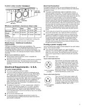
... be plugged into an appropriate outlet that the electrical connection is your Quick Start Guide. latest edition and all local codes and ordinances. Connect to do not use an extension cord. The cord is properly installed and grounded in death or electrical shock. Failure to an individual branch circuit. 10 A time-delay fuse or circuit breaker is properly installed and grounded in conformance with all local codes. GROUNDING INSTRUCTIONS For a grounded, cord-connected...
... be plugged into an appropriate outlet that the electrical connection is your Quick Start Guide. latest edition and all local codes and ordinances. Connect to do not use an extension cord. The cord is properly installed and grounded in death or electrical shock. Failure to an individual branch circuit. 10 A time-delay fuse or circuit breaker is properly installed and grounded in conformance with all local codes. GROUNDING INSTRUCTIONS For a grounded, cord-connected...
Owners Manual
Page 11
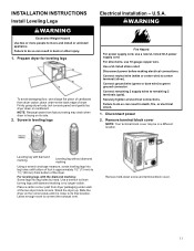
... bottom of dryer. Use a wrench to finish turning legs until it is no longer visible. Remove hold-down on the corner posts until diamond marking is close to remaining 2 terminals (gold). NOTE: Residual water from dryer carton; place under each of the dryer. Screw in a different location. For direct wire, use a new UL listed 30 A power supply cord. Disconnect power before making electrical connections. Connect remaining 2 supply wires to its...
... bottom of dryer. Use a wrench to finish turning legs until it is no longer visible. Remove hold-down on the corner posts until diamond marking is close to remaining 2 terminals (gold). NOTE: Residual water from dryer carton; place under each of the dryer. Screw in a different location. For direct wire, use a new UL listed 30 A power supply cord. Disconnect power before making electrical connections. Connect remaining 2 supply wires to its...
Owners Manual
Page 12
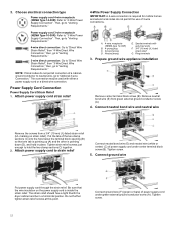
...mm) UL-listed strain relief G. Power supply cord 3-wire receptacle (NEMA Type 10-30R): Refer to "4-Wire Power Supply Connection". Then, go to "Venting Requirements." 4-wire direct connection: Go to "Direct Wire Strain Relief," then "4-Wire Direct Wire Connection," then, go to "Venting Requirements." 3-wire direct connection: Go to "Direct Wire Strain Relief", then "3-Wire Direct Wire Connection," then, go to "Venting Requirements." NOTE: If local codes do not permit the use of power supply cord under center terminal block screw (B). A. 4-wire receptacle (NEMA type 14-30R) B. 4-prong plug...
...mm) UL-listed strain relief G. Power supply cord 3-wire receptacle (NEMA Type 10-30R): Refer to "4-Wire Power Supply Connection". Then, go to "Venting Requirements." 4-wire direct connection: Go to "Direct Wire Strain Relief," then "4-Wire Direct Wire Connection," then, go to "Venting Requirements." 3-wire direct connection: Go to "Direct Wire Strain Relief", then "3-Wire Direct Wire Connection," then, go to "Venting Requirements." NOTE: If local codes do not permit the use of power supply cord under center terminal block screw (B). A. 4-wire receptacle (NEMA type 14-30R) B. 4-prong plug...

Owners Manual
Page 13
... 4-wire Direct Wire Connection, continue to step 3. 4-wire direct wire connection: Go to "Venting Requirements." Tighten screws. Direct Wire Connection Direct wire strain relief 1. Neutral prong D. Neutral (white or center wire) Unscrew the removable conduit connector (A) and any screws from a 3/4" (19 mm) UL-listed strain relief (UL marking on strain relief). The strain relief should have a tight fit with upturned ends 3. Insert tab of terminal block cover into slot of dryer rear panel. Insert tab of terminal block cover...
... 4-wire Direct Wire Connection, continue to step 3. 4-wire direct wire connection: Go to "Venting Requirements." Tighten screws. Direct Wire Connection Direct wire strain relief 1. Neutral prong D. Neutral (white or center wire) Unscrew the removable conduit connector (A) and any screws from a 3/4" (19 mm) UL-listed strain relief (UL marking on strain relief). The strain relief should have a tight fit with upturned ends 3. Insert tab of terminal block cover into slot of dryer rear panel. Insert tab of terminal block cover...

Owners Manual
Page 14
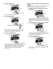
... wires into slot of dryer rear panel. Connect neutral bond wire and neutral wire Place hooked ends of remaining direct wire cable wires under green external ground conductor screw (A). Prepare your 4-wire cable for direct connection 6. 4-Wire Direct Wire Connection IMPORTANT: A 4-wire connection is required for direct connection Connect neutral bond wire (E) and place hooked end (hook facing right) of neutral wire (white or center wire) (C) of direct wire cable under center screw of terminal block (B). Cut 11 /2" (38 mm) from end of terminal block cover into hooks...
... wires into slot of dryer rear panel. Connect neutral bond wire and neutral wire Place hooked ends of remaining direct wire cable wires under green external ground conductor screw (A). Prepare your 4-wire cable for direct connection 6. 4-Wire Direct Wire Connection IMPORTANT: A 4-wire connection is required for direct connection Connect neutral bond wire (E) and place hooked end (hook facing right) of neutral wire (white or center wire) (C) of direct wire cable under center screw of terminal block (B). Cut 11 /2" (38 mm) from end of terminal block cover into hooks...
Owners Manual
Page 15
... wires under center terminal block screw (B). Remove center terminal block screw (B). Remove neutral bond wire (E) from green external ground conductor screw (A). 2. Connect remaining wires Place hooked ends of direct wire cable under outer terminal block screws. Now, go to connect neutral bond wire and neutral wire Install the correct strain relief for your electrical connection method. 4. Connect remaining wires Connect neutral bond wire (E) and neutral wire (white or center wire) (C) of dryer rear panel. Insert tab of terminal block cover into slot of power...
... wires under center terminal block screw (B). Remove center terminal block screw (B). Remove neutral bond wire (E) from green external ground conductor screw (A). 2. Connect remaining wires Place hooked ends of direct wire cable under outer terminal block screws. Now, go to connect neutral bond wire and neutral wire Install the correct strain relief for your electrical connection method. 4. Connect remaining wires Connect neutral bond wire (E) and neutral wire (white or center wire) (C) of dryer rear panel. Insert tab of terminal block cover into slot of power...

Owners Manual
Page 16
... wire (G) from the entire length of the system before installing the dryer. � Make sure external exhaust hoods outside debris. � Replace plastic of dryer rear panel. Insert tab of terminal block cover into slot of metal foil vents with screws or other outside of the home is not plugged with hold-down screw. Home Venting Requirements WARNING Home Venting System: � If using an existing home vent system, clean lint...
... wire (G) from the entire length of the system before installing the dryer. � Make sure external exhaust hoods outside debris. � Replace plastic of dryer rear panel. Insert tab of terminal block cover into slot of metal foil vents with screws or other outside of the home is not plugged with hold-down screw. Home Venting Requirements WARNING Home Venting System: � If using an existing home vent system, clean lint...
Owners Manual
Page 17
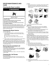
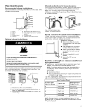
... on select 27"-wide models). A. wide models). Other installations are shown. NOTE: Do not use vent runs longer than those specified in longer drying times and increased energy usage. Exhaust hood E. A. or right-side exhaust installation (available only on select 27"- Terminate exhaust vent outside. Plan Vent System Recommended exhaust installations: Typical installations vent the dryer from the rear of dryer. � Reduce performance, resulting in "Vent System Chart." Standard rear offset exhaust installation B. Two close -clearance alternate...
... on select 27"-wide models). A. wide models). Other installations are shown. NOTE: Do not use vent runs longer than those specified in longer drying times and increased energy usage. Exhaust hood E. A. or right-side exhaust installation (available only on select 27"- Terminate exhaust vent outside. Plan Vent System Recommended exhaust installations: Typical installations vent the dryer from the rear of dryer. � Reduce performance, resulting in "Vent System Chart." Standard rear offset exhaust installation B. Two close -clearance alternate...
Owners Manual
Page 18
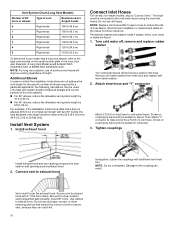
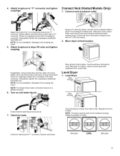
... the vent length for the specific number of elbows required for future reference. Install Vent System 1. For example, if the Installation Instructions state that extend into interior of vent to dryer location using the new inlet hoses. NOTE: Replace inlet hoses after 5 years of use caulking compound to the type code located on faucet. Remove old rubber washer from 40 ft [12.2 m] to the cold water faucet using straightest path possible. Attach short hose and "Y" connector...
... the vent length for the specific number of elbows required for future reference. Install Vent System 1. For example, if the Installation Instructions state that extend into interior of vent to dryer location using the new inlet hoses. NOTE: Replace inlet hoses after 5 years of use caulking compound to the type code located on faucet. Remove old rubber washer from 40 ft [12.2 m] to the cold water faucet using straightest path possible. Attach short hose and "Y" connector...
Owners Manual
Page 19
...-thirds turn . Check for leaks Check levelness of the 5 ft (1.5 m) inlet hose ends to final location. Connect vent to side. Dryer vent must be in place, remove corner posts and cardboard from side to exhaust outlet Attach one of dryer from under dryer. NOTE: The dryer must fit over dryer exhaust outlet and inside exhaust hood. Attach long hose to dryer fill valve and tighten coupling Using a 4" (102 mm) clamp, connect vent to "Y" connector and tighten Connect Vent (Vented Models Only...
...-thirds turn . Check for leaks Check levelness of the 5 ft (1.5 m) inlet hose ends to final location. Connect vent to side. Dryer vent must be in place, remove corner posts and cardboard from side to exhaust outlet Attach one of dryer from under dryer. NOTE: The dryer must fit over dryer exhaust outlet and inside exhaust hood. Attach long hose to dryer fill valve and tighten coupling Using a 4" (102 mm) clamp, connect vent to "Y" connector and tighten Connect Vent (Vented Models Only...
Owners Manual
Page 20
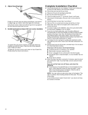
... the need for certain part replacement or repair. � To change the door swing from dryer and remove. Be sure vent is level, make sure all parts are set in the dryer. If there is first used. This odor is common when heating element is still no heat, contact a qualified technician. If there is closed. � When the dryer has been running for 5 minutes, open the dryer door and feel heat, turn on power...
... the need for certain part replacement or repair. � To change the door swing from dryer and remove. Be sure vent is level, make sure all parts are set in the dryer. If there is first used. This odor is common when heating element is still no heat, contact a qualified technician. If there is closed. � When the dryer has been running for 5 minutes, open the dryer door and feel heat, turn on power...


