Specification Sheet
Page 1
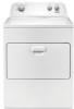
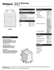
...General Features & Properties Timed Dry 3 Drying Temperatures 7.0 Cu. For complete details, see Installation Instructions packed with intermittent tumbling after the dryer cycle ends. Specifications subject to the laundry basket without notice. ®/™ © 2020. WED4850HSpecSheetV01. ft. Technical Details Drum ...purposes only. Printed in the U.S.A. Hamper Door Easily transfer loads from the washer to the dryer and from setting into your clean clothes with product. All rights reserved. Electric Dryer WED4850H White WED4850HW Capacity Total 7.0 cu. 7.0 cu.
...General Features & Properties Timed Dry 3 Drying Temperatures 7.0 Cu. For complete details, see Installation Instructions packed with intermittent tumbling after the dryer cycle ends. Specifications subject to the laundry basket without notice. ®/™ © 2020. WED4850HSpecSheetV01. ft. Technical Details Drum ...purposes only. Printed in the U.S.A. Hamper Door Easily transfer loads from the washer to the dryer and from setting into your clean clothes with product. All rights reserved. Electric Dryer WED4850H White WED4850HW Capacity Total 7.0 cu. 7.0 cu.

Installation Instructions
Page 2
DRYER SAFETY 2
DRYER SAFETY 2
Installation Instructions
Page 4
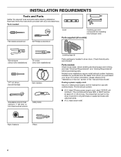
... a power supply cord: Use a UL listed power supply cord kit marked for purchase from the dealer from whom you purchased your dryer. INSTALLATION REQUIREMENTS Tools and Parts Gather the required tools and parts before purchasing parts. The cord should contain: ■■ A UL... (direct wire installations) Tin snips (new vent installations) 1/4" nut driver (recommended) Vent clamps Adjustable wrench that opens to the dryer must end in dryer drum. Check that connect to 1" (25 mm) or hex-head socket wrench Utility knife Leveling legs (4) Parts package is located...
... a power supply cord: Use a UL listed power supply cord kit marked for purchase from the dealer from whom you purchased your dryer. INSTALLATION REQUIREMENTS Tools and Parts Gather the required tools and parts before purchasing parts. The cord should contain: ■■ A UL... (direct wire installations) Tin snips (new vent installations) 1/4" nut driver (recommended) Vent clamps Adjustable wrench that opens to the dryer must end in dryer drum. Check that connect to 1" (25 mm) or hex-head socket wrench Utility knife Leveling legs (4) Parts package is located...
Installation Instructions
Page 5
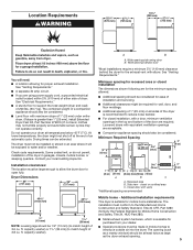
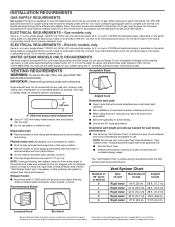
... (38 mm) (to match height of 200 lbs. (90.7 kg). Wide opening hamper door *Most installations require a minimum 5½" (140 mm) clearance behind the dryer for the exhaust vent with elbow. Minimum Required Spacing 18"* (457 mm) 14" max.* (356 mm) 48 in.2* (310 cm )2 3"* (76 mm) 24 ... door with maximum slope of 3.6 cu. See "Electrical Requirements." ■■ A sturdy floor to support the total weight (dryer and load) of 3.8 cu. At lower temperatures, the dryer might be exposed to water and/or weather. Some codes limit, or do not permit, installation of the door are for...
... (38 mm) (to match height of 200 lbs. (90.7 kg). Wide opening hamper door *Most installations require a minimum 5½" (140 mm) clearance behind the dryer for the exhaust vent with elbow. Minimum Required Spacing 18"* (457 mm) 14" max.* (356 mm) 48 in.2* (310 cm )2 3"* (76 mm) 24 ... door with maximum slope of 3.6 cu. See "Electrical Requirements." ■■ A sturdy floor to support the total weight (dryer and load) of 3.8 cu. At lower temperatures, the dryer might be exposed to water and/or weather. Some codes limit, or do not permit, installation of the door are for...
Installation Instructions
Page 6
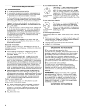
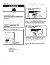
...9632;■ A 4-wire power supply connection must have a fuse in a location where grounding through the neutral conductor is installed with clothes dryers. When the neutral ground wire is secured under the neutral terminal (center or white wire) of NEMA Type 10-30R. A time-...grounding circuit. ■■ Do not use aluminum). ■■ At least 5 ft. (1.52 m) long. 6 Electrical Connection To properly install your dryer, you will be using a power supply cord: Use a UL listed power supply cord kit marked for (1) new branch-circuit installations, (2) mobile homes, ...
...9632;■ A 4-wire power supply connection must have a fuse in a location where grounding through the neutral conductor is installed with clothes dryers. When the neutral ground wire is secured under the neutral terminal (center or white wire) of NEMA Type 10-30R. A time-...grounding circuit. ■■ Do not use aluminum). ■■ At least 5 ft. (1.52 m) long. 6 Electrical Connection To properly install your dryer, you will be using a power supply cord: Use a UL listed power supply cord kit marked for (1) new branch-circuit installations, (2) mobile homes, ...

Installation Instructions
Page 7
...is approximately 1/2" (13 mm) (to steps 1-2 on its final location. capacity washer) from dryer carton; Then, go to steps 1-2 on cardboard. 2. Firmly grasp dryer body (not console panel) and gently lay dryer down on page 9 for power supply cord strain relief: then steps 3-6 for 4-wire Direct ...strain relief: then steps 3-7 for leveling legs To avoid damaging floor, use a large flat piece of cardboard from bottom of 3.6 cu. Prepare dryer for 3-wire Direct Wire Connection section. capacity washer) or 1½" (38 mm) (to connect the exhaust vent. Leave enough room for 3-wire...
...is approximately 1/2" (13 mm) (to steps 1-2 on its final location. capacity washer) from dryer carton; Then, go to steps 1-2 on cardboard. 2. Firmly grasp dryer body (not console panel) and gently lay dryer down on page 9 for power supply cord strain relief: then steps 3-6 for 4-wire Direct ...strain relief: then steps 3-7 for leveling legs To avoid damaging floor, use a large flat piece of cardboard from bottom of 3.6 cu. Prepare dryer for 3-wire Direct Wire Connection section. capacity washer) or 1½" (38 mm) (to connect the exhaust vent. Leave enough room for 3-wire...
Installation Instructions
Page 8
... cord strain relief 1. Hold-down screw E. Do not further tighten strain relief screws at this point. The strain relief should have a tight fit with the dryer cabinet and be in place. Direct Wire 2. Hole below the terminal block opening so that the wire insulation on strain relief).
... cord strain relief 1. Hold-down screw E. Do not further tighten strain relief screws at this point. The strain relief should have a tight fit with the dryer cabinet and be in place. Direct Wire 2. Hole below the terminal block opening so that the wire insulation on strain relief).

Installation Instructions
Page 9
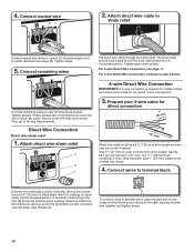
... type 14-30R) B. 4-prong plug C. Ring terminals 3. Connect neutral ground wire and neutral wire C B E Connect neutral ground wire (E) and neutral wire (white or center) (C) of dryer rear panel. Spade terminals with upturned ends F. 3/4" (19 mm) UL listed strain relief G. Neutral prong E. F Connect ground wire (F) (green or bare) of 3-wire connections. Tighten...
... type 14-30R) B. 4-prong plug C. Ring terminals 3. Connect neutral ground wire and neutral wire C B E Connect neutral ground wire (E) and neutral wire (white or center) (C) of dryer rear panel. Spade terminals with upturned ends F. 3/4" (19 mm) UL listed strain relief G. Neutral prong E. F Connect ground wire (F) (green or bare) of 3-wire connections. Tighten...
Installation Instructions
Page 10
... a tight fit with hold-down screw. Reaching inside the terminal block opening . The strain relief should have 5 ft. (1.52 m) of dryer rear panel. Tighten strain relief screws. Now, go to outer terminal block screws. Direct Wire Connection Direct wire strain relief 1. Prepare your 4-... not permit 3-wire connections. 3. For 3-wire Direct Wire Connection, see page 11. Shape ends of wires into slot of extra length so dryer may be in a horizontal position. Connect remaining wires to Venting Requirements. Strip 5" (127 mm) of terminal block cover into hooks. 4. ...
... a tight fit with hold-down screw. Reaching inside the terminal block opening . The strain relief should have 5 ft. (1.52 m) of dryer rear panel. Tighten strain relief screws. Now, go to outer terminal block screws. Direct Wire Connection Direct wire strain relief 1. Prepare your 4-... not permit 3-wire connections. 3. For 3-wire Direct Wire Connection, see page 11. Shape ends of wires into slot of extra length so dryer may be in a horizontal position. Connect remaining wires to Venting Requirements. Strip 5" (127 mm) of terminal block cover into hooks. 4. ...
Installation Instructions
Page 11
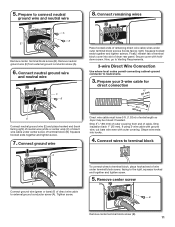
... hooked ends together and tighten screws. Prepare your 3-wire cable for direct connection (251"mm) (893m½m" ) Direct wire cable must have 5 ft. (1.52 m) of dryer rear panel. Strip insulation back 1" (25 mm). To connect wires to terminal block, place hooked end of direct wire cable to the right, squeeze hooked... ends of remaining direct wire cable wires under center screw of terminal block cover into hooks. 4. Shape wire ends into slot of extra length so dryer may be moved if needed. 5. Connect remaining wires A B E Remove center terminal block screw (B).
... hooked ends together and tighten screws. Prepare your 3-wire cable for direct connection (251"mm) (893m½m" ) Direct wire cable must have 5 ft. (1.52 m) of dryer rear panel. Strip insulation back 1" (25 mm). To connect wires to terminal block, place hooked end of direct wire cable to the right, squeeze hooked... ends of remaining direct wire cable wires under center screw of terminal block cover into hooks. 4. Shape wire ends into slot of extra length so dryer may be moved if needed. 5. Connect remaining wires A B E Remove center terminal block screw (B).

Installation Instructions
Page 12
Connect neutral ground wire and neutral wire B C Place hooked end of neutral wire (white or center) (C) of dryer rear panel. Squeeze hooked ends together and tighten screws. Connect external ground wire A A B E Remove center terminal block screw (B). G Connect a ...Secure cover with hold-down screw. 6. Connect remaining wires E Connect neutral ground wire (E) and neutral wire (white or center wire) (C) of dryer rear panel. Remove neutral ground wire (E) from the external ground conductor screw (A) to connect neutral ground wire and neutral wire 4. Finally, reinsert tab...
Connect neutral ground wire and neutral wire B C Place hooked end of neutral wire (white or center) (C) of dryer rear panel. Squeeze hooked ends together and tighten screws. Connect external ground wire A A B E Remove center terminal block screw (B). G Connect a ...Secure cover with hold-down screw. 6. Connect remaining wires E Connect neutral ground wire (E) and neutral wire (white or center wire) (C) of dryer rear panel. Remove neutral ground wire (E) from the external ground conductor screw (A) to connect neutral ground wire and neutral wire 4. Finally, reinsert tab...
Installation Instructions
Page 13
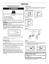
...reduced airflow and poor performance. ■■ Do not install in final dryer location. ■■ Remove excess to achieve best drying performance. Do not use plastic or metal foil vent. Dryer exhaust must not be connected or secured with screws or other fastening devices that...a building. Venting Requirements VENTING Exhaust hoods: ■■ Must be at least 12" (305 mm) from entire length of fire, this dryer MUST BE EXHAUSTED OUTDOORS. Review "Vent System Chart" and, if necessary, modify existing vent system to avoid sagging and kinking that may obstruct exhaust...
...reduced airflow and poor performance. ■■ Do not install in final dryer location. ■■ Remove excess to achieve best drying performance. Do not use plastic or metal foil vent. Dryer exhaust must not be connected or secured with screws or other fastening devices that...a building. Venting Requirements VENTING Exhaust hoods: ■■ Must be at least 12" (305 mm) from entire length of fire, this dryer MUST BE EXHAUSTED OUTDOORS. Review "Vent System Chart" and, if necessary, modify existing vent system to avoid sagging and kinking that may obstruct exhaust...
Installation Instructions
Page 14
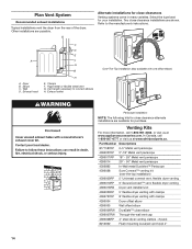
...length necessary to the manufacturer's instructions. Exhaust outlet Over-The-Top installation (also available with clamps 4396004 Dryer offset elbow 4396005 Wall offset elbow 4396006RW DuraSafe™ close clearance alternate installations are available for close -clearance...Exhaust hood C D E F G B H E. Clamps F. In Canada, call 1-800-901-2042, or visit us at www.applianceaccessories.com. Dryer B. B Alternate installations for purchase. Wall D. Part Number Descriptions 8171587RP 0-5" Metal vent periscope 4396037RP 0"-18" Metal vent periscope 4396011RP 18" - 29...
...length necessary to the manufacturer's instructions. Exhaust outlet Over-The-Top installation (also available with clamps 4396004 Dryer offset elbow 4396005 Wall offset elbow 4396006RW DuraSafe™ close clearance alternate installations are available for close -clearance...Exhaust hood C D E F G B H E. Clamps F. In Canada, call 1-800-901-2042, or visit us at www.applianceaccessories.com. Dryer B. B Alternate installations for purchase. Wall D. Part Number Descriptions 8171587RP 0-5" Metal vent periscope 4396037RP 0"-18" Metal vent periscope 4396011RP 18" - 29...
Installation Instructions
Page 15
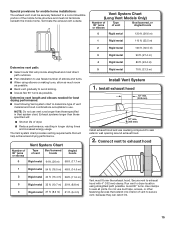
... and increased energy usage. Vent System Chart Number of 90° turns or elbows Type of dryer. ■■ Reduce performance, resulting in Vent system chart. Secure vent to seal all joints. Run vent to dryer location using elbows or making turns, allow as much room as possible. ■■ Bend vent...
... and increased energy usage. Vent System Chart Number of 90° turns or elbows Type of dryer. ■■ Reduce performance, resulting in Vent system chart. Secure vent to seal all joints. Run vent to dryer location using elbows or making turns, allow as much room as possible. ■■ Bend vent...
Installation Instructions
Page 16
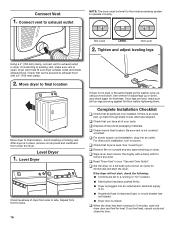
... is secured to exhaust hood with a damp cloth to exhaust outlet NOTE: The dryer must fit over dryer exhaust outlet and inside exhaust hood. Level Dryer 1. q Dispose of/recycle all of dryer from under the dryer. q Check dryer's final location. Tighten and adjust leveling legs Using a 4" (102 mm) clamp, ...connect vent to existing vent, make sure all parts are level, make sure vent is in a running for 5 minutes, open the dryer door and feel heat, cancel cycle and close the door. If connecting to exhaust outlet in your tools. q Check that all four legs are ...
... is secured to exhaust hood with a damp cloth to exhaust outlet NOTE: The dryer must fit over dryer exhaust outlet and inside exhaust hood. Level Dryer 1. q Dispose of/recycle all of dryer from under the dryer. q Check dryer's final location. Tighten and adjust leveling legs Using a 4" (102 mm) clamp, ...connect vent to existing vent, make sure all parts are level, make sure vent is in a running for 5 minutes, open the dryer door and feel heat, cancel cycle and close the door. If connecting to exhaust outlet in your tools. q Check that all four legs are ...
Installation Instructions
Page 17
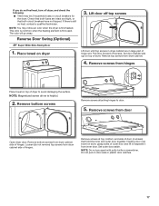
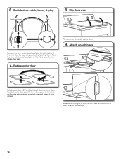
... towel on top of hinges. Pull door forward off screws. Remove screws from dryer cabinet side of dryer to door. 5. Remove bottom screws from hinges Place towel on dryer, grasp sides of outer door and lift to separate it from dryer cabinet side of door (4 screws) that both fuses are in large part of.... 4. Place towel on door seal or plastic door catches. 17 Lift door off top screws Lift door until top screws in dryer cabinet are intact and tight, or that hold the inner and outer door together. Check that both circuit breakers have not tripped. If you do ...
... towel on top of hinges. Pull door forward off screws. Remove screws from dryer cabinet side of dryer to door. 5. Remove bottom screws from hinges Place towel on dryer, grasp sides of outer door and lift to separate it from dryer cabinet side of door (4 screws) that both fuses are in large part of.... 4. Place towel on door seal or plastic door catches. 17 Lift door off top screws Lift door until top screws in dryer cabinet are intact and tight, or that hold the inner and outer door together. Check that both circuit breakers have not tripped. If you do ...
Installation Instructions
Page 18
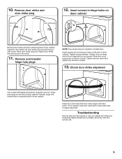
... door by squeezing and pulling/pushing them. Rotate outer door Rotate outer door 180º and set it back down . 9. Reattach outer door panel to dryer door so that the larger hole is down on the side where hinges were just removed. Insert 4 door screws. Reattach door hinges to inner door...
... door by squeezing and pulling/pushing them. Rotate outer door Rotate outer door 180º and set it back down . 9. Reattach outer door panel to dryer door so that the larger hole is down on the side where hinges were just removed. Insert 4 door screws. Reattach door hinges to inner door...
Installation Instructions
Page 19
... Tighten screws. Check door strike alignment Use a small, flat-blade screwdriver to reinstall door. 10. Insert screws in hinge holes on opposite side of dryer cabinet. Position door so large end of door hinge slot is needed to gently remove 4 hinge hole plugs on left side of slots. Remove door ...strike hole and secure with door catch. Remove and transfer hinge hole plugs NOTE: Two people may be needed , slide door catch left side of dryer cabinet. Slide door up so screws are in hinges. 13. Transfer plugs into the bottom holes on left or right within slot to possibly avoid...
... Tighten screws. Check door strike alignment Use a small, flat-blade screwdriver to reinstall door. 10. Insert screws in hinge holes on opposite side of dryer cabinet. Position door so large end of door hinge slot is needed to gently remove 4 hinge hole plugs on left side of slots. Remove door ...strike hole and secure with door catch. Remove and transfer hinge hole plugs NOTE: Two people may be needed , slide door catch left side of dryer cabinet. Slide door up so screws are in hinges. 13. Transfer plugs into the bottom holes on left or right within slot to possibly avoid...

Dimension Guide
Page 1
... and servicing, spacing for companion appliances, and clearances for walls, doors, and floor moldings. Gas and Electric Dryer PRODUCT MODEL NUMBERS WED4950HW, WGD4950HW, WED4850HW, WGD4850HW, YWED4850HW Installation clearances: For each arrangement, consider allowing more space for ease of the dryer in garages, closets, mobile homes, or sleeping quarters. Space must be required for...
... and servicing, spacing for companion appliances, and clearances for walls, doors, and floor moldings. Gas and Electric Dryer PRODUCT MODEL NUMBERS WED4950HW, WGD4950HW, WED4850HW, WGD4850HW, YWED4850HW Installation clearances: For each arrangement, consider allowing more space for ease of the dryer in garages, closets, mobile homes, or sleeping quarters. Space must be required for...
Dimension Guide
Page 2
... used . ■■ Do not use with Natural gas. IMPORTANT: Observe all governing codes and ordinances. Acceptable Style: Dryer exhaust must be connected to change materials and specifications without notice. Determine vent length and elbows needed for your washer using elbows... 27 ft. (8.2 m) 58 ft. (17.7 m) 48 ft. (14.6 m) 38 ft. (11.6 m) 29 ft. (8.8 m) 21 ft. (6.4 m) Louvered hood Box hood Because Whirlpool Corporation policy includes a continuous commitment to improve our products, we reserve the right to avoid kinking. ■■ Use as few 90° turns as...
... used . ■■ Do not use with Natural gas. IMPORTANT: Observe all governing codes and ordinances. Acceptable Style: Dryer exhaust must be connected to change materials and specifications without notice. Determine vent length and elbows needed for your washer using elbows... 27 ft. (8.2 m) 58 ft. (17.7 m) 48 ft. (14.6 m) 38 ft. (11.6 m) 29 ft. (8.8 m) 21 ft. (6.4 m) Louvered hood Box hood Because Whirlpool Corporation policy includes a continuous commitment to improve our products, we reserve the right to avoid kinking. ■■ Use as few 90° turns as...


