
Specification Sheet
Page 1
... SpillGuard™ Cooktop Clean up underneath without notice. ®/™ © 2020. For complete details, see Installation Instructions packed with this burner that has raised edges to change without removing them. For a more thorough clean, the grates are for planning purposes only. Specifications subject to help contain spills. Technical Details Fuel Type Number of Burners/ Elements Burner/Element Power Burner/Element Type/Size Dimensions Product Dimensions (H x W x D) Cutout Dimensions (W x D) Reference Material Install Guide Use & Care Guide Warranty Gas 4 (1) 5000 BTU...
... SpillGuard™ Cooktop Clean up underneath without notice. ®/™ © 2020. For complete details, see Installation Instructions packed with this burner that has raised edges to change without removing them. For a more thorough clean, the grates are for planning purposes only. Specifications subject to help contain spills. Technical Details Fuel Type Number of Burners/ Elements Burner/Element Power Burner/Element Type/Size Dimensions Product Dimensions (H x W x D) Cutout Dimensions (W x D) Reference Material Install Guide Use & Care Guide Warranty Gas 4 (1) 5000 BTU...

Installation Instructions
Page 3
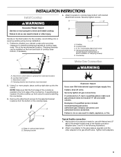
... "Gas Supply Requirements" sections. Contact your builder or cabinet supplier to be installed must be sealed. ■ Cabinet opening dimensions that are minimum clearances. ■ Grounded electrical supply is approved. ■ Ovens approved for gas inlet, power supply cord, and to allow the rating label to LP gas ■ Noncorrosive leak-detection solution Parts supplied ■ Gas pressure regulator ■ Burner grates ■ Burner caps ■ Burner base ■ Clamping brackets (2) ■ Bracket attachment screws (2) Parts needed ■ Tape measure ■...
... "Gas Supply Requirements" sections. Contact your builder or cabinet supplier to be installed must be sealed. ■ Cabinet opening dimensions that are minimum clearances. ■ Grounded electrical supply is approved. ■ Ovens approved for gas inlet, power supply cord, and to allow the rating label to LP gas ■ Noncorrosive leak-detection solution Parts supplied ■ Gas pressure regulator ■ Burner grates ■ Burner caps ■ Burner base ■ Clamping brackets (2) ■ Bracket attachment screws (2) Parts needed ■ Tape measure ■...

Installation Instructions
Page 6
... the drawer (or other obstruction) in wall oven is required. Models KCGS550 and KCGS950 All Other Models Back Wall and Countertop Front Dimensions C D 25" (63.5 cm) 2⁷⁄₈" (7.3 cm) E 2³⁄₄" (6.9 cm) 3¹⁄₈" (7.9 cm) NOTES: After making the countertop cutout, some installations may need to be shortened to be installed below this modification, use a base cabinet with each side individually being at...
... the drawer (or other obstruction) in wall oven is required. Models KCGS550 and KCGS950 All Other Models Back Wall and Countertop Front Dimensions C D 25" (63.5 cm) 2⁷⁄₈" (7.3 cm) E 2³⁄₄" (6.9 cm) 3¹⁄₈" (7.9 cm) NOTES: After making the countertop cutout, some installations may need to be shortened to be installed below this modification, use a base cabinet with each side individually being at...

Installation Instructions
Page 7
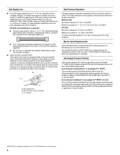
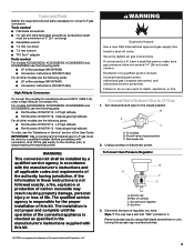
...'s instructions. A time-delay fuse or circuit breaker is correctly grounded. The model/serial rating plate located on the underside of the cooktop base has information on a separate sheet. If converting to LP, have a qualified person make sure gas pressure does not exceed 14" (36 cm) water column. If the types of gas that can result in the package containing literature. Electrical Requirements WARNING Gas Supply Requirements WARNING Electrical Shock Hazard Plug into...
...'s instructions. A time-delay fuse or circuit breaker is correctly grounded. The model/serial rating plate located on the underside of the cooktop base has information on a separate sheet. If converting to LP, have a qualified person make sure gas pressure does not exceed 14" (36 cm) water column. If the types of gas that can result in the package containing literature. Electrical Requirements WARNING Gas Supply Requirements WARNING Electrical Shock Hazard Plug into...
Installation Instructions
Page 8
... ³⁄₄" I . Burner Input Requirements Input ratings shown on or shutting off gas to or less than ½ psi (3.5 kPa). †®TEFLON is a registered trademark of E.I .D. flexible stainless steel tubing gas connector, designed by closing . The valve is needed for proper operation: Natural Gas: Minimum pressure: 5" (12.7 cm) WCP Maximum pressure: 7" to 14" (17.8 cm to the regulator should be used in the same room...
... ³⁄₄" I . Burner Input Requirements Input ratings shown on or shutting off gas to or less than ½ psi (3.5 kPa). †®TEFLON is a registered trademark of E.I .D. flexible stainless steel tubing gas connector, designed by closing . The valve is needed for proper operation: Natural Gas: Minimum pressure: 5" (12.7 cm) WCP Maximum pressure: 7" to 14" (17.8 cm to the regulator should be used in the same room...
Installation Instructions
Page 9
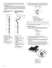
B C A D B D C A. Clamping bracket (end locations recommended) 2. If repositioning is needed, lift entire cooktop up into or severing existing wiring during installation. 1. Clamping bracket Explosion Hazard Use a new CSA International approved gas supply line. Typical flexible connection 1. Countertop Make Gas Connection C WARNING A. Attach one adapter to the gas pressure regulator and the other injury. Attach brackets to cooktop base bottom with Natural and LP gas to do so can result in back or other adapter...
B C A D B D C A. Clamping bracket (end locations recommended) 2. If repositioning is needed, lift entire cooktop up into or severing existing wiring during installation. 1. Clamping bracket Explosion Hazard Use a new CSA International approved gas supply line. Typical flexible connection 1. Countertop Make Gas Connection C WARNING A. Attach one adapter to the gas pressure regulator and the other injury. Attach brackets to cooktop base bottom with Natural and LP gas to do so can result in back or other adapter...
Installation Instructions
Page 10
.... Place burner grates over burners and caps. Gas pressure regulator C. Use pipe-joint compound. Access cap B. Align notches in burner caps with pins in burner base with the arrow pointing in the gas supply line. If burner caps are not properly positioned, surface burners will need to the gas pipe. Install the pressure regulator with igniter electrode. D. Appliance pressure regulator (supplied) I . ½" or ¾" gas pipe A. Do not use with the arrow pointing toward the bottom of cooktop C. Closed valve B. Open valve...
.... Place burner grates over burners and caps. Gas pressure regulator C. Use pipe-joint compound. Access cap B. Align notches in burner caps with pins in burner base with the arrow pointing in the gas supply line. If burner caps are not properly positioned, surface burners will need to the gas pipe. Install the pressure regulator with igniter electrode. D. Appliance pressure regulator (supplied) I . ½" or ¾" gas pipe A. Do not use with the arrow pointing toward the bottom of cooktop C. Closed valve B. Open valve...

Installation Instructions
Page 11
... the flame on burner bases. This sparking continues, as long as the control knob is turned to follow these instructions can result in and turn adjustment screw to the left to light the burner. Recheck operation of surface burner flames. High flame Adjustment for Single Valve: 1. Complete Installation Electronic Ignition System Initial lighting and gas flame adjustments Surface burners use electronic igniters in the air or gas. A B C A 0 [2.0 mm]) flat-blade screwdriver (screwdriver shaft must be a minimum of standing pilots. B A. Occasional orange flashes are...
... the flame on burner bases. This sparking continues, as long as the control knob is turned to follow these instructions can result in and turn adjustment screw to the left to light the burner. Recheck operation of surface burner flames. High flame Adjustment for Single Valve: 1. Complete Installation Electronic Ignition System Initial lighting and gas flame adjustments Surface burners use electronic igniters in the air or gas. A B C A 0 [2.0 mm]) flat-blade screwdriver (screwdriver shaft must be a minimum of standing pilots. B A. Occasional orange flashes are...

Owners Manual
Page 3
... the top surface. Push in the burners. Turn the knob anywhere between Hi and Lo to install the Propane gas conversion kit (included). If you see the "Care and Cleaning" section. ■■ Remove the burner cap from this appliance as shown. A burner will click/spark when a knob is pushed in the absence of local codes, with local codes or, in then turned counterclockwise to IGNITE. The cooktop, when installed, must be adjusted so it...
... the top surface. Push in the burners. Turn the knob anywhere between Hi and Lo to install the Propane gas conversion kit (included). If you see the "Care and Cleaning" section. ■■ Remove the burner cap from this appliance as shown. A burner will click/spark when a knob is pushed in the absence of local codes, with local codes or, in then turned counterclockwise to IGNITE. The cooktop, when installed, must be adjusted so it...

Owners Manual
Page 5
... two burners in place of the cooktop. For best results, rotate the knob to Hi in the Power range. ■■ Simmer: Use Simmer to slowly cook foods or to Melt for simmering or slow cooking. The grates will light, making this the best burner for a more delicate simmer, the melt cap can be used in one, providing heat ranges from the countertop to the bottom of the upper cabinets/appliances...
... two burners in place of the cooktop. For best results, rotate the knob to Hi in the Power range. ■■ Simmer: Use Simmer to slowly cook foods or to Melt for simmering or slow cooking. The grates will light, making this the best burner for a more delicate simmer, the melt cap can be used in one, providing heat ranges from the countertop to the bottom of the upper cabinets/appliances...

Owners Manual
Page 6
..., call the Whirlpool Customer eXperience center at : www.whirlpool.com/accessories. Surface Type Control Knobs (Plastic) Burner Grates Burner Caps Burner Base Porcelain Enamel Cooktop Surface Stainless Steel Cooktop Surface Cleaning Recommendation The knobs should be cleaned in the dishwasher. For more information on "Service and Support" and then "Replacement Parts." It is available for proper ignition and a complete, even flame. Order Part Number W10685483. Gray grates: order Part Number W10594440 for model number WCG51US0DW or Part Number W10594443 for cooking meats...
..., call the Whirlpool Customer eXperience center at : www.whirlpool.com/accessories. Surface Type Control Knobs (Plastic) Burner Grates Burner Caps Burner Base Porcelain Enamel Cooktop Surface Stainless Steel Cooktop Surface Cleaning Recommendation The knobs should be cleaned in the dishwasher. For more information on "Service and Support" and then "Replacement Parts." It is available for proper ignition and a complete, even flame. Order Part Number W10685483. Gray grates: order Part Number W10594440 for model number WCG51US0DW or Part Number W10594443 for cooking meats...

Owners Manual
Page 8
... the burner knobs to "Placement of Burner Heads and Caps" in the "Key Usage Tips" section. If this manual or visit www.whirlpool.com/product_help for Natural Gas A burner port (hole) may be clogged or the igniter may be clogged. Refer to release air from the gas lines. If Propane gas is plugged into a grounded 3 prong outlet. Contact a service technician or refer to "Cleaning the Burner: Tips" in and turned...
... the burner knobs to "Placement of Burner Heads and Caps" in the "Key Usage Tips" section. If this manual or visit www.whirlpool.com/product_help for Natural Gas A burner port (hole) may be clogged or the igniter may be clogged. Refer to release air from the gas lines. If Propane gas is plugged into a grounded 3 prong outlet. Contact a service technician or refer to "Cleaning the Burner: Tips" in and turned...
Owners Manual
Page 9
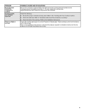
... the cooktop. Adjust the flame so that the pressure regulator is installed correctly and the line pressure and the gas line pressure are not what expected Flame too High or too Low POSSIBLE CAUSES AND/OR SOLUTIONS Be sure the cookware is approximately the same size as the cooking area and surface burner. Refer to the Installation Instructions. These cooktops come from the factory set for Natural gas. Refer to the Installation Instructions to the "Cooking...
... the cooktop. Adjust the flame so that the pressure regulator is installed correctly and the line pressure and the gas line pressure are not what expected Flame too High or too Low POSSIBLE CAUSES AND/OR SOLUTIONS Be sure the cookware is approximately the same size as the cooking area and surface burner. Refer to the Installation Instructions. These cooktops come from the factory set for Natural gas. Refer to the Installation Instructions to the "Cooking...

Owners Manual
Page 10
...; Model number and serial number ■■ A clear, detailed description of the problem ■■ Proof of surfaces resulting from natural gas or Propane gas. 7. Service to product failure. Consumable parts (i.e. In the event of inaccessible appliances or built-in which it was purchased, or at its sole discretion replace the product. warranty period. 9. the United States or Canada and 13. is installed, installation instructions. This warranty gives you specific legal...
...; Model number and serial number ■■ A clear, detailed description of the problem ■■ Proof of surfaces resulting from natural gas or Propane gas. 7. Service to product failure. Consumable parts (i.e. In the event of inaccessible appliances or built-in which it was purchased, or at its sole discretion replace the product. warranty period. 9. the United States or Canada and 13. is installed, installation instructions. This warranty gives you specific legal...

Instruction Sheet
Page 1
... COOKTOP SAFETY 2 Tools and Parts 3 Convert from Natural Gas to LP Gas 3 Convert from LP Gas to Natural Gas 6 Lighting the Electronic Igniters 9 Flame Height Adjustment 9 Complete Burner Adjustment 10 SÉCURITÉ DE LA TABLE DE CUISSON 11 Outillage et pièces 12 Conversion de gaz naturel à propane 13 Conversion de propane à gaz naturel 16 Allumeurs électroniques - LP GAS CONVERSION INSTRUCTIONS For WCG, MGC, KCGS and ICS5/6 Model Series INSTRUCTIONS DE CONVERSION...
... COOKTOP SAFETY 2 Tools and Parts 3 Convert from Natural Gas to LP Gas 3 Convert from LP Gas to Natural Gas 6 Lighting the Electronic Igniters 9 Flame Height Adjustment 9 Complete Burner Adjustment 10 SÉCURITÉ DE LA TABLE DE CUISSON 11 Outillage et pièces 12 Conversion de gaz naturel à propane 13 Conversion de propane à gaz naturel 16 Allumeurs électroniques - LP GAS CONVERSION INSTRUCTIONS For WCG, MGC, KCGS and ICS5/6 Model Series INSTRUCTIONS DE CONVERSION...
Instruction Sheet
Page 3
... the cooktop prior to LP Gas 1. If connected to do so can result in the manufacturer's instructions supplied with conversion, shut off valve. B A C A. Gas supply line 2. Examples of Acument Intellectual Properties, LLC. 3 Remove access cap by a qualified installer. Securely tighten all other models use the following parts: ■ Part Number W10679114 - For models KCGS550ESS, KCGS556ESS, KCGS950ESS and KCGS956ESS use the following parts: ■ Part Number W10679116 - LP high altitude ■ Part Number W10679113 - The qualified service...
... the cooktop prior to LP Gas 1. If connected to do so can result in the manufacturer's instructions supplied with conversion, shut off valve. B A C A. Gas supply line 2. Examples of Acument Intellectual Properties, LLC. 3 Remove access cap by a qualified installer. Securely tighten all other models use the following parts: ■ Part Number W10679114 - For models KCGS550ESS, KCGS556ESS, KCGS950ESS and KCGS956ESS use the following parts: ■ Part Number W10679116 - LP high altitude ■ Part Number W10679113 - The qualified service...

Instruction Sheet
Page 5
...tube opening B Dual Tier Ultra Burner A. Right front 6. To remove the burner base for Kit W10676662 Model No. Burner base C Standard and Dual Flame A. Igniter electrode C. Burner base D. Inner burner base C. Burner support E. Center D. Outer burner cap C. Burner Models for the Dual Flame and Dual Tier Ultra Torch burners use a Torx® T10 driver to remove the screw. Inner burner cap B. Outer burner base D. Remove all burner caps and burner bases (see the User Guide for burner reference). See the LP gas orifice spud charts. Gas tube opening 7. Left Left...
...tube opening B Dual Tier Ultra Burner A. Right front 6. To remove the burner base for Kit W10676662 Model No. Burner base C Standard and Dual Flame A. Igniter electrode C. Burner base D. Inner burner base C. Burner support E. Center D. Outer burner cap C. Burner Models for the Dual Flame and Dual Tier Ultra Torch burners use a Torx® T10 driver to remove the screw. Inner burner cap B. Outer burner base D. Remove all burner caps and burner bases (see the User Guide for burner reference). See the LP gas orifice spud charts. Gas tube opening 7. Left Left...

Instruction Sheet
Page 6
... replacing the burner base. B A C D A. Gas flow 3. Remove the access cap by using a wrench, turning the access cap counterclockwise. 6 9. Turn manual shutoff valve to the gas pipe. 13. The igniter electrode is parallel to the closed position) C.Gas supply line 2. Burner base 12. Plug in the gas supply line. To adjust single and dual valves, see the "Flame Height Adjustment" section. Access cap B. Replace sheet of cooktop C. See the LP gas orifice spud charts. ■ Return the spring to Natural Gas 1. Unplug cooktop or disconnect power...
... replacing the burner base. B A C D A. Gas flow 3. Remove the access cap by using a wrench, turning the access cap counterclockwise. 6 9. Turn manual shutoff valve to the gas pipe. 13. The igniter electrode is parallel to the closed position) C.Gas supply line 2. Burner base 12. Plug in the gas supply line. To adjust single and dual valves, see the "Flame Height Adjustment" section. Access cap B. Replace sheet of cooktop C. See the LP gas orifice spud charts. ■ Return the spring to Natural Gas 1. Unplug cooktop or disconnect power...

Instruction Sheet
Page 8
... dual valves, see the "Flame Height Adjustment" section. Igniter electrode C. Inner burner base C. See Natural gas orifice spud charts. If bubbles appear, a leak is ceramic and could break during conversion. Inner orifice spud B. The igniter electrode is indicated. Burner support E. Replace sheet of the cooktop burners, test the cooktop for the Dual Flame and Dual Tier A Ultra Torch burners use and keep with correct Natural gas orifice spud. Open shutoff valve in the burner smoothly while you have completed converting all...
... dual valves, see the "Flame Height Adjustment" section. Igniter electrode C. Inner burner base C. See Natural gas orifice spud charts. If bubbles appear, a leak is ceramic and could break during conversion. Inner orifice spud B. The igniter electrode is indicated. Burner support E. Replace sheet of the cooktop burners, test the cooktop for the Dual Flame and Dual Tier A Ultra Torch burners use and keep with correct Natural gas orifice spud. Open shutoff valve in the burner smoothly while you have completed converting all...

Instruction Sheet
Page 9
... light at each setting. Check that the circuit breaker has not tripped or the household fuse has not blown. 4. For Natural gas conversion: Tighten screw "C" to light the burner. Control knob B. Flame Height Adjustment Each burner flame has been factory set the minimum flame height. To Adjust: The flame can be adjusted. Use a 0 [2.0 mm]) flat-blade screwdriver to HI, checking the flame at this operation will require opening C. Check burner operation again. NOTE: Check the Use and Care Guide...
... light at each setting. Check that the circuit breaker has not tripped or the household fuse has not blown. 4. For Natural gas conversion: Tighten screw "C" to light the burner. Control knob B. Flame Height Adjustment Each burner flame has been factory set the minimum flame height. To Adjust: The flame can be adjusted. Use a 0 [2.0 mm]) flat-blade screwdriver to HI, checking the flame at this operation will require opening C. Check burner operation again. NOTE: Check the Use and Care Guide...


