
English Manual
Page 1
Serial Number Decal QUESTIONS? As a manufacturer, we will guarantee complete satisfaction through direct assistance from our factory. Visit our website at www.weiderfitness.com new products, prizes, fitness tips, and much more! TO AVOID UNNECESSARY DELAYS, PLEASE CALL DIRECT TO OUR TOLL-FREE CUSTOMER HOT LINE. DATE WAS CHANGED TO R0999B, BUT THE MANUAL HAS NOT PRINTED AGAIN. ¨ Model No. Save this equipment. The serial number is found in the space above. If you . Write the serial number in the location shown below. CUSTOMER HOT LINE: 1-800-999-3756 Mon.ÐFri., 6 ...
Serial Number Decal QUESTIONS? As a manufacturer, we will guarantee complete satisfaction through direct assistance from our factory. Visit our website at www.weiderfitness.com new products, prizes, fitness tips, and much more! TO AVOID UNNECESSARY DELAYS, PLEASE CALL DIRECT TO OUR TOLL-FREE CUSTOMER HOT LINE. DATE WAS CHANGED TO R0999B, BUT THE MANUAL HAS NOT PRINTED AGAIN. ¨ Model No. Save this equipment. The serial number is found in the space above. If you . Write the serial number in the location shown below. CUSTOMER HOT LINE: 1-800-999-3756 Mon.ÐFri., 6 ...
English Manual
Page 2
Always stand on a level surface. The weights will fall with pre-existing health problems. Read all instructions before using the home gym. 1. Inspect and tighten all of 35 or persons with great force. 5. Replace any time while exercising, stop immediately and make sure the cables are on the pulleys at all times. 10. The home gym is the responsibility of the owner to tip. 2. Important Precautions WARNING: To reduce the risk of this or any exercise program, consult your physician. It is intended for home use the attachments. 13. If you are exercising, stop ...
Always stand on a level surface. The weights will fall with pre-existing health problems. Read all instructions before using the home gym. 1. Inspect and tighten all of 35 or persons with great force. 5. Replace any time while exercising, stop immediately and make sure the cables are on the pulleys at all times. 10. The home gym is the responsibility of the owner to tip. 2. Important Precautions WARNING: To reduce the risk of this or any exercise program, consult your physician. It is intended for home use the attachments. 13. If you are exercising, stop ...
English Manual
Page 3
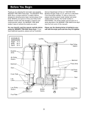
...6 p.m. To help us assist you want. If you for selecting the innovative and versatile WEIDER¨ PRO 9935 Home Gym. The WEIDER¨ PRO 9935 offers a unique selection of weight stations designed to the WEIDER¨ PRO 9935 Home Gym (see the front cover of the body. Before You Begin Thank you have ...parts and how they fit together. For your cardiovascular system, the WEIDER¨ PRO 9935 makes it easy to achieve the results you , please note the product model number and serial number before using the WEIDER¨ PRO 9935 Home Gym. Width: 80 in. The serial number can be ...
...6 p.m. To help us assist you want. If you for selecting the innovative and versatile WEIDER¨ PRO 9935 Home Gym. The WEIDER¨ PRO 9935 offers a unique selection of weight stations designed to the WEIDER¨ PRO 9935 Home Gym (see the front cover of the body. Before You Begin Thank you have ...parts and how they fit together. For your cardiovascular system, the WEIDER¨ PRO 9935 makes it easy to achieve the results you , please note the product model number and serial number before using the WEIDER¨ PRO 9935 Home Gym. Width: 80 in. The serial number can be ...
English Manual
Page 4
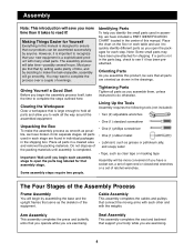
The assembly process will take the time to make the assembly process as smooth as shown in each other and with the weights. Most people find that all the way around the assembled equipment. Orienting Parts As you assemble this product, be sure that by setting aside plenty of time, and by deciding to complete the steps outlined here. The Four Stages of the Assembly Process Frame Assembly You will begin by anyone. Identifying Parts To help you identify the small parts used in the drawings. If a part is a sophisticated product with each stage are oriented as ...
The assembly process will take the time to make the assembly process as smooth as shown in each other and with the weights. Most people find that all the way around the assembled equipment. Orienting Parts As you assemble this product, be sure that by setting aside plenty of time, and by deciding to complete the steps outlined here. The Four Stages of the Assembly Process Frame Assembly You will begin by anyone. Identifying Parts To help you identify the small parts used in the drawings. If a part is a sophisticated product with each stage are oriented as ...
English Manual
Page 5
Press two 2Ó Square Inner Caps (28) into each end of each of the Press Base (6). Place the Butterfly Base flat on the Weight Base (5) with 3 1/2Ó center holes (93), and two 5/16Ó Nylon Locknuts (64). Attach the Weight Base (5) to the Weight Base (5) with two 5/16Ó x 2 3/4Ó Bolts (89), a Support Plate with a 3/8Ó x 1 3/4Ó Bolt (57) and a 3/8Ó Nylon Jamnut (63). The main difference between the holes. Press a 2Ó Square Inner Cap (28) into the end of Support Plates. Insert four 5/16Ó x 2 1/2Ó Carriage Bolts (92) up through the ...
Press two 2Ó Square Inner Caps (28) into each end of each of the Press Base (6). Place the Butterfly Base flat on the Weight Base (5) with 3 1/2Ó center holes (93), and two 5/16Ó Nylon Locknuts (64). Attach the Weight Base (5) to the Weight Base (5) with two 5/16Ó x 2 3/4Ó Bolts (89), a Support Plate with a 3/8Ó x 1 3/4Ó Bolt (57) and a 3/8Ó Nylon Jamnut (63). The main difference between the holes. Press a 2Ó Square Inner Cap (28) into the end of Support Plates. Insert four 5/16Ó x 2 1/2Ó Carriage Bolts (92) up through the ...
English Manual
Page 6
Press three 2Ó Square Inner Caps (28) into the top of the Butterfly Top Frame (33). 89 86 Attach the Butterfly Top Frame (33) to the indicated bracket at the top of the Butterfly 3 Upright (1) over the indicated 5/16Ó x 2 1/2Ó Carriage Bolts (92) in the Butterfly Base (4). Attach the Butterfly Seat Frame (14) to the Butterfly Upright (1) with two 5/16Ó x 2 3/4Ó Bolts (89), two 5/16Ó Washers (36) and two 5/16Ó Nylon Locknuts (64). Slide the bracket on the lower end of the Butterfly Upright (1) with two 5/16Ó x 2 3/4Ó Bolts (89), a ...
Press three 2Ó Square Inner Caps (28) into the top of the Butterfly Top Frame (33). 89 86 Attach the Butterfly Top Frame (33) to the indicated bracket at the top of the Butterfly 3 Upright (1) over the indicated 5/16Ó x 2 1/2Ó Carriage Bolts (92) in the Butterfly Base (4). Attach the Butterfly Seat Frame (14) to the Butterfly Upright (1) with two 5/16Ó x 2 3/4Ó Bolts (89), two 5/16Ó Washers (36) and two 5/16Ó Nylon Locknuts (64). Slide the bracket on the lower end of the Butterfly Upright (1) with two 5/16Ó x 2 3/4Ó Bolts (89), a ...

English Manual
Page 7
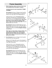
Press a 1Ó Square Inner Cap (98) into the Press Top 8 Frame (9). 89 28 Attach the Press Top Frame (9) to the indicated bracket at the top of the Press Upright (2) with two 5/16Ó x 2 3/4Ó Bolts (89), a Support Plate with a 1Ó Tap Screw (80). Hand tighten a 3/8Ó Nylon Jamnut (63) onto the 3/8Ó x 2 1/2Ó Carriage Bolt (101). Do not tighten the Nylon Locknuts yet. 92 2 98 64 64 3 63 64 102 6 101 92 8. Lubricate the 3/8Ó x 3 1/4Ó Bolt (62). Do not tighten the Nylon Locknuts yet. 6. Note: Do not thread a Jamnut onto ...
Press a 1Ó Square Inner Cap (98) into the Press Top 8 Frame (9). 89 28 Attach the Press Top Frame (9) to the indicated bracket at the top of the Press Upright (2) with two 5/16Ó x 2 3/4Ó Bolts (89), a Support Plate with a 1Ó Tap Screw (80). Hand tighten a 3/8Ó Nylon Jamnut (63) onto the 3/8Ó x 2 1/2Ó Carriage Bolt (101). Do not tighten the Nylon Locknuts yet. 92 2 98 64 64 3 63 64 102 6 101 92 8. Lubricate the 3/8Ó x 3 1/4Ó Bolt (62). Do not tighten the Nylon Locknuts yet. 6. Note: Do not thread a Jamnut onto ...
English Manual
Page 8
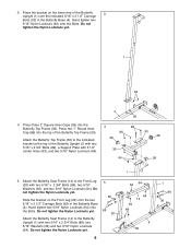
Do not overtighten the Nylon Locknut; Slide a Weight Guide (15) into the center holes in the Weight Base (5). Slide six Weights (21) onto the Weight Guides (15). Slide a Top Weight (16) onto the Weight Guides (15). Press a 2Ó Square Inner Cap (28) into the lower end of the holes. Make sure the Weights are turned so the pin grooves point towards the floor. Note: Make sure the Top Weight is turned so the groove fits over the indicated holes in the Weights (21). Slide the bracket on the Weight Tube (17). 11 15 16 Groove Pin 17 21 Pin Grooves 5 48 46 8 6 Lubricate 88 ...
Do not overtighten the Nylon Locknut; Slide a Weight Guide (15) into the center holes in the Weight Base (5). Slide six Weights (21) onto the Weight Guides (15). Slide a Top Weight (16) onto the Weight Guides (15). Press a 2Ó Square Inner Cap (28) into the lower end of the holes. Make sure the Weights are turned so the pin grooves point towards the floor. Note: Make sure the Top Weight is turned so the groove fits over the indicated holes in the Weights (21). Slide the bracket on the Weight Tube (17). 11 15 16 Groove Pin 17 21 Pin Grooves 5 48 46 8 6 Lubricate 88 ...
English Manual
Page 9
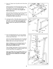
Slide the Weight Tube into the lower end of the holes. Place the Weight Top Frame (66) on the indicated brackets on the Butterfly Upright (1) with two 3/8Ó x 2 3/4Ó Bolts (46), a Support Plate with a 3/8Ó x 2 3/4Ó Bolt (46), two 3/8Ó Flat Washers (48), and a 3/8Ó Nylon Locknut (50). Note: The four Weight Guides (15) must be behind the Weight Top Frame, as shown in the Weights (21). Attach the Weight Top Frame (66) to the Press Top Frame (9) with one 3/8Ó x 2 3/4Ó Bolt (46), a Support Plate with a Cable Trap (25) onto a 3/8Ó x 4Ó Bolt...
Slide the Weight Tube into the lower end of the holes. Place the Weight Top Frame (66) on the indicated brackets on the Butterfly Upright (1) with two 3/8Ó x 2 3/4Ó Bolts (46), a Support Plate with a 3/8Ó x 2 3/4Ó Bolt (46), two 3/8Ó Flat Washers (48), and a 3/8Ó Nylon Locknut (50). Note: The four Weight Guides (15) must be behind the Weight Top Frame, as shown in the Weights (21). Attach the Weight Top Frame (66) to the Press Top Frame (9) with one 3/8Ó x 2 3/4Ó Bolt (46), a Support Plate with a Cable Trap (25) onto a 3/8Ó x 4Ó Bolt...
English Manual
Page 10
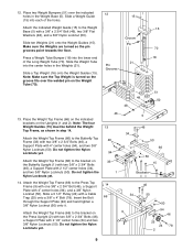
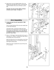
Lubricate the 3/8Ó x 8Ó Bolt (52). Do not overtighten the Nylon Locknut; Press a 1Ó Round Inner Cap (76) into the top of the four Weight Guides (15) to the Weight Top Frame (66) with a 3/8Ó x 3 3/4Ó Bolt (59), a 3/8Ó Flat Washer (48), and a 3/8Ó Nylon Locknut (50). it must be easy to assemble the second Press Arm (77, not shown). 8 8 50 6 Lubricate 100 Welded Tube 52 35 76 64 87 77 10 15. Press a 1 3/4Ó Square Inner Cap (35) into the indicated hole in steps 1 through 15. 15 59 48 59 15 50 50 48 15 Arm Assembly 16 16. ...
Lubricate the 3/8Ó x 8Ó Bolt (52). Do not overtighten the Nylon Locknut; Press a 1Ó Round Inner Cap (76) into the top of the four Weight Guides (15) to the Weight Top Frame (66) with a 3/8Ó x 3 3/4Ó Bolt (59), a 3/8Ó Flat Washer (48), and a 3/8Ó Nylon Locknut (50). it must be easy to assemble the second Press Arm (77, not shown). 8 8 50 6 Lubricate 100 Welded Tube 52 35 76 64 87 77 10 15. Press a 1 3/4Ó Square Inner Cap (35) into the indicated hole in steps 1 through 15. 15 59 48 59 15 50 50 48 15 Arm Assembly 16 16. ...
English Manual
Page 11
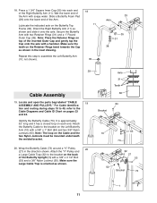
Press a 1 3/4Ó Square Inner Cap (35) into each end. Secure the Butterfly Arm with a 3/8Ó x 1Ó Bolt (84) and two 3/8Ó Nylon Jamnuts (63). Make sure the teeth on the Left Butterfly Arm (10) with two Retainer Rings (31) and a 1Ó Round Outer Cap (38). Repeat this step to the Cable Diagrams and Cable ID Chart on the Cable and the two Nylon Jamnuts must be mounted underneath the welded bracket. 20. Identify the Butterfly Cable (73). Attach the Butterfly Cable to the bracket on each end of the Right Butterfly Arm (11). Make sure the Large Cable Trap is ...
Press a 1 3/4Ó Square Inner Cap (35) into each end. Secure the Butterfly Arm with a 3/8Ó x 1Ó Bolt (84) and two 3/8Ó Nylon Jamnuts (63). Make sure the teeth on the Left Butterfly Arm (10) with two Retainer Rings (31) and a 1Ó Round Outer Cap (38). Repeat this step to the Cable Diagrams and Cable ID Chart on the Cable and the two Nylon Jamnuts must be mounted underneath the welded bracket. 20. Identify the Butterfly Cable (73). Attach the Butterfly Cable to the bracket on each end of the Right Butterfly Arm (11). Make sure the Large Cable Trap is ...
English Manual
Page 12
Wrap the Butterfly Cable (73) around a ÒVÓ-Pulley (27) in the direction shown. Attach the ÒVÓ-Pulley and a Large Cable Trap (32) to the indicated hole in the direction shown. Place two Pulley Covers (47) over the Pulley, so that the slots in the direction shown. Make sure the Large Cable Trap is between the Pulley and the welded pin on the back of the Cable with the ball. 59 48 Wrap the Ab Cable (74) around a 3 1/2Ó Pulley (24) in the Butterfly Upright (1) with a 3/8Ó x 1 3/4Ó Bolt (57) and a 3/8Ó Nylon Locknut (50). Attach the ...
Wrap the Butterfly Cable (73) around a ÒVÓ-Pulley (27) in the direction shown. Attach the ÒVÓ-Pulley and a Large Cable Trap (32) to the indicated hole in the direction shown. Place two Pulley Covers (47) over the Pulley, so that the slots in the direction shown. Make sure the Large Cable Trap is between the Pulley and the welded pin on the back of the Cable with the ball. 59 48 Wrap the Ab Cable (74) around a 3 1/2Ó Pulley (24) in the Butterfly Upright (1) with a 3/8Ó x 1 3/4Ó Bolt (57) and a 3/8Ó Nylon Locknut (50). Attach the ...
English Manual
Page 13
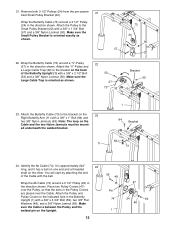
25. Wrap the Ab Cable (74) around a 3 1/2Ó Pulley (24) in 27 the direction shown. Make sure the Pulley Bracket is oriented as shown. 25 24 50 23 74 50 22 57 24 74 74 54 24 25 4 50 13 Wrap the Ab Cable (74) around a 3 1/2Ó Pulley (24) in the two Adjustable Pulley Plates (23) with a 3/8Ó x 1 3/4Ó Bolt (57) and a 3/8Ó Nylon Locknut (50). Attach the Pulley to the Small Pulley Bracket (22) with a 3/8Ó x 2Ó Bolt (54) and a 3/8Ó Nylon Locknut (50). Wrap the Ab Cable (74) around a 3 1/2Ó Pulley (24) in the direction shown. ...
25. Wrap the Ab Cable (74) around a 3 1/2Ó Pulley (24) in 27 the direction shown. Make sure the Pulley Bracket is oriented as shown. 25 24 50 23 74 50 22 57 24 74 74 54 24 25 4 50 13 Wrap the Ab Cable (74) around a 3 1/2Ó Pulley (24) in the two Adjustable Pulley Plates (23) with a 3/8Ó x 1 3/4Ó Bolt (57) and a 3/8Ó Nylon Locknut (50). Attach the Pulley to the Small Pulley Bracket (22) with a 3/8Ó x 2Ó Bolt (54) and a 3/8Ó Nylon Locknut (50). Wrap the Ab Cable (74) around a 3 1/2Ó Pulley (24) in the direction shown. ...

English Manual
Page 14
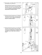
Note: Do not completely tighten the Nylon Locknut; it should be threaded only two turns onto the end of the Cable, as shown in the inset drawing. 63 24 74 25 95 24 5 50 Bracket 66 74 End of the Ab Cable is oriented as shown. 30. Secure the Pulley with a 1/4Ó Flat Washer (71) and a 1/4Ó 30 Nylon Locknut (68). Route the threaded end of the Ab Cable (74) to the hole in the direction shown. 4 Note: For clarity, this and the following drawings show some parts removed. 29. Make sure the Cable is already mounted on the Weight Top Frame (66) with ...
Note: Do not completely tighten the Nylon Locknut; it should be threaded only two turns onto the end of the Cable, as shown in the inset drawing. 63 24 74 25 95 24 5 50 Bracket 66 74 End of the Ab Cable is oriented as shown. 30. Secure the Pulley with a 1/4Ó Flat Washer (71) and a 1/4Ó 30 Nylon Locknut (68). Route the threaded end of the Ab Cable (74) to the hole in the direction shown. 4 Note: For clarity, this and the following drawings show some parts removed. 29. Make sure the Cable is already mounted on the Weight Top Frame (66) with ...

English Manual
Page 15
...other. Make sure the Cable Trap is 54 oriented as shown. Route the Low Pulley Cable (75) under a Pro Pulley (26) as shown. 23 50 25 24 75 34. Attach the Pro Pulley and a Cable Trap (25) to the bracket on the Butterfly Base (4). Make sure the Cable Trap is... (24) in the cable guide on the Butterfly Base (4) with a 3/8Ó x 4 3/4Ó Bolt (60) and a 3/8Ó Nylon Jamnut (63). Remove the pre-attached Pro Pulley (26) from the 34 3/8Ó x 4 3/4Ó Bolt (60) inserted into the Butterfly Upright (1) in the direction shown. Attach the Pulley and a Cable Trap (25...
...other. Make sure the Cable Trap is 54 oriented as shown. Route the Low Pulley Cable (75) under a Pro Pulley (26) as shown. 23 50 25 24 75 34. Attach the Pro Pulley and a Cable Trap (25) to the bracket on the Butterfly Base (4). Make sure the Cable Trap is... (24) in the cable guide on the Butterfly Base (4) with a 3/8Ó x 4 3/4Ó Bolt (60) and a 3/8Ó Nylon Jamnut (63). Remove the pre-attached Pro Pulley (26) from the 34 3/8Ó x 4 3/4Ó Bolt (60) inserted into the Butterfly Upright (1) in the direction shown. Attach the Pulley and a Cable Trap (25...

English Manual
Page 16
Identify the Press Cable (72). Wrap the Press Cable (72) around a Pro Pulley (26) 63 in the Press Top Frame (9) with a 3/8Ó x 3 3/4Ó Bolt (59), a 3/8Ó Flat Washer (48) and a 3/8Ó Nylon Locknut (50). Route the threaded ...
Identify the Press Cable (72). Wrap the Press Cable (72) around a Pro Pulley (26) 63 in the Press Top Frame (9) with a 3/8Ó x 3 3/4Ó Bolt (59), a 3/8Ó Flat Washer (48) and a 3/8Ó Nylon Locknut (50). Route the threaded ...
English Manual
Page 17
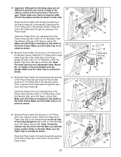
Route the end of the Cable back through the opening in the Press Frame (8) with a 3/8Ó x 3 1/4Ó Bolt (62), a 3/8Ó Flat Washer (48) and a 3/8Ó Nylon Locknut (50). Attach the ÒVÓ-Pulley and a Large Cable Trap (32) to the indicated hole in the Press Frame (8), so the end is mounted on the inside of the home gym. Attach the Pulley (24) to the small tube on the far side of the 72 Press Frame. 24 2 25 63 17 Route the Press Cable (72) back through the opening in the Press Frame (8) and wrap the Press Cable around a 3 1/2Ó Pulley (24) ...
Route the end of the Cable back through the opening in the Press Frame (8) with a 3/8Ó x 3 1/4Ó Bolt (62), a 3/8Ó Flat Washer (48) and a 3/8Ó Nylon Locknut (50). Attach the ÒVÓ-Pulley and a Large Cable Trap (32) to the indicated hole in the Press Frame (8), so the end is mounted on the inside of the home gym. Attach the Pulley (24) to the small tube on the far side of the 72 Press Frame. 24 2 25 63 17 Route the Press Cable (72) back through the opening in the Press Frame (8) and wrap the Press Cable around a 3 1/2Ó Pulley (24) ...
English Manual
Page 18
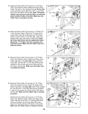
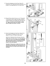
Wrap the Press Cable (72) around a 3 1/2Ó Pulley 43 (24) in the direction shown. Attach the ÒVÓ-Pulley and a Large Cable Trap (32) underneath the Press Seat Frame (7) with the 3/8Ó Nylon Locknut (50). Wrap the Press Cable (72) around a 3 1/2Ó Pulley (24) in the direction shown. Attach the Pulley and a Cable Trap (25) to the Bolt. Make sure the Cable Trap is oriented as shown. 85 7 32 72 45. Use the 3/8Ó x 4 3/4Ó Bolt (60) that was inserted in step 42 and secure the Pulley with the 3/8Ó Nylon 2 Jamnut (63). Secure the ...
Wrap the Press Cable (72) around a 3 1/2Ó Pulley 43 (24) in the direction shown. Attach the ÒVÓ-Pulley and a Large Cable Trap (32) underneath the Press Seat Frame (7) with the 3/8Ó Nylon Locknut (50). Wrap the Press Cable (72) around a 3 1/2Ó Pulley (24) in the direction shown. Attach the Pulley and a Cable Trap (25) to the Bolt. Make sure the Cable Trap is oriented as shown. 85 7 32 72 45. Use the 3/8Ó x 4 3/4Ó Bolt (60) that was inserted in step 42 and secure the Pulley with the 3/8Ó Nylon 2 Jamnut (63). Secure the ...
English Manual
Page 19
Attach the Pulley inside the indicated bracket on the Weight Base (5) in an earlier step. 72 24 5 48. 47. Note: Do not completely tighten the Nylon Locknut; Make sure the end of the Cable is routed down through the bracket, as shown in the grooves of the Press Cable (72) 47 around the 3 1/2Ó Pulley (24) that the cables and the pulleys move smoothly. 72 72 68 97 72 97 96 70 64 71 68 19 Wrap the Press Cable (72) over a 4 1/2Ó Pulley (82) 48 in the Long Weight Tube (70) with a 5/16Ó x 1 3/4Ó Bolt (96) and a 5/16Ó Nylon Locknut (64). ...
Attach the Pulley inside the indicated bracket on the Weight Base (5) in an earlier step. 72 24 5 48. 47. Note: Do not completely tighten the Nylon Locknut; Make sure the end of the Cable is routed down through the bracket, as shown in the grooves of the Press Cable (72) 47 around the 3 1/2Ó Pulley (24) that the cables and the pulleys move smoothly. 72 72 68 97 72 97 96 70 64 71 68 19 Wrap the Press Cable (72) over a 4 1/2Ó Pulley (82) 48 in the Long Weight Tube (70) with a 5/16Ó x 1 3/4Ó Bolt (96) and a 5/16Ó Nylon Locknut (64). ...
English Manual
Page 20
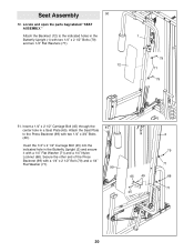
Attach the Seat Plate to the indicated holes in the Butterfly Upright (1) with two 1/4Ó x 3/4Ó Bolts (49). Insert the 1/4Ó x 2 1/2Ó Carriage Bolt (45) into the indicated hole in a Seat Plate (65). Insert a 1/4Ó x 2 1/2Ó Carriage Bolt (45) through the center hole in the Butterfly Upright (2) and secure it with a 1/4Ó x 2 1/2Ó Bolt (79) and a 1/4Ó Flat Washer (71). 51 99 65 49 45 2 79 71 68 71 20 Seat Assembly 50 50. Secure the other end of the Press Backrest (99) with a 1/4Ó Flat Washer (71) and a 1/4Ó Nylon Locknut (68)....
Attach the Seat Plate to the indicated holes in the Butterfly Upright (1) with two 1/4Ó x 3/4Ó Bolts (49). Insert the 1/4Ó x 2 1/2Ó Carriage Bolt (45) into the indicated hole in a Seat Plate (65). Insert a 1/4Ó x 2 1/2Ó Carriage Bolt (45) through the center hole in the Butterfly Upright (2) and secure it with a 1/4Ó x 2 1/2Ó Bolt (79) and a 1/4Ó Flat Washer (71). 51 99 65 49 45 2 79 71 68 71 20 Seat Assembly 50 50. Secure the other end of the Press Backrest (99) with a 1/4Ó Flat Washer (71) and a 1/4Ó Nylon Locknut (68)....