

English Manual
Page 2
... decal(s) may not be shown at actual size. 2 TABLE OF CONTENTS WARNING DECAL PLACEMENT 2 IMPORTANT PRECAUTIONS 3 BEFORE YOU BEGIN 4 PART IDENTIFICATION CHART 5 ASSEMBLY 6 ADJUSTMENT 21 WEIGHT RESISTANCE CHART 23 CABLE DIAGRAM 24 MAINTENANCE 25 EXERCISE GUIDELINES 26 PART LIST 29 EXPLODED DRAWING 30 ORDERING REPLACEMENT PARTS Back Cover 90 DAY FULL WARRANTY...
... decal(s) may not be shown at actual size. 2 TABLE OF CONTENTS WARNING DECAL PLACEMENT 2 IMPORTANT PRECAUTIONS 3 BEFORE YOU BEGIN 4 PART IDENTIFICATION CHART 5 ASSEMBLY 6 ADJUSTMENT 21 WEIGHT RESISTANCE CHART 23 CABLE DIAGRAM 24 MAINTENANCE 25 EXERCISE GUIDELINES 26 PART LIST 29 EXPLODED DRAWING 30 ORDERING REPLACEMENT PARTS Back Cover 90 DAY FULL WARRANTY...
English Manual
Page 6
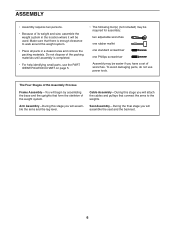
... where it will attach the cables and pulleys that form the skeleton of the weight system. Arm Assembly—-During this stage you will be easier if you have a set of wrenches. Cable Assembly—-During this stage you will assemble the arms and the leg ...lever. Do not dispose of the packing materials until assembly is enough clearance to the weights. Seat Assembly—-During the final stage you will assemble the seat and the backrest. 6 ASSEMBLY •• Assembly requires two...
... where it will attach the cables and pulleys that form the skeleton of the weight system. Arm Assembly—-During this stage you will be easier if you have a set of wrenches. Cable Assembly—-During this stage you will assemble the arms and the leg ...lever. Do not dispose of the packing materials until assembly is enough clearance to the weights. Seat Assembly—-During the final stage you will assemble the seat and the backrest. 6 ASSEMBLY •• Assembly requires two...
English Manual
Page 11
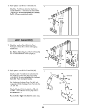
... grease to the Left Arm (10) 12 9 with two M4 x 20mm Self-tapping Screws (69). Do not overtighten the Locknut; the Cable Pivot must pivot easily. 56 5 4 Grease 79 Arm Assembly 11 11. Attach a Handle (11) to the Pivot Frame (5) with the M10 x 51mm Bolt (66) and an M10 Locknut (56). Attach... Left Arm (10) with the M10 x 77mm Bolt (79) and an M10 Locknut (56). Slide the Large Foam Pad onto the Left Arm (10). Attach a Cable Pivot (39) to an M10 x 51mm Bolt (66). Wet the inside of a Large Foam Pad (42) with soapy water. Do not overtighten the Locknut; See...
... grease to the Left Arm (10) 12 9 with two M4 x 20mm Self-tapping Screws (69). Do not overtighten the Locknut; the Cable Pivot must pivot easily. 56 5 4 Grease 79 Arm Assembly 11 11. Attach a Handle (11) to the Pivot Frame (5) with the M10 x 51mm Bolt (66) and an M10 Locknut (56). Attach... Left Arm (10) with the M10 x 77mm Bolt (79) and an M10 Locknut (56). Slide the Large Foam Pad onto the Left Arm (10). Attach a Cable Pivot (39) to an M10 x 51mm Bolt (66). Wet the inside of a Large Foam Pad (42) with soapy water. Do not overtighten the Locknut; See...

English Manual
Page 12
...grease to identify the cables as you assemble them. the Left Arm must pivot easily. Identify the Arm Cable (54). See the CABLE DIAGRAM on page 24 to an M8 x 22mm Shoulder Bolt (65). 13. Attach the Left Arm (10) to the left Cable Pivot (39) ...M10 Washer (57), and an M10 Locknut (56). Attach the Right Arm (9) to two Arm Bushings (44). Attach the Arm Cable (54) to the Pivot Frame (5) with the M8 x 22mm Shoulder Bolt (65) and an M8 Locknut (58). 58 ... Frame (5) in the same way. 9 5 67 20 Grease 44 57 56 Grease 10 44 Cable Assembly 14 14. Do not overtighten the Locknut;
...grease to identify the cables as you assemble them. the Left Arm must pivot easily. Identify the Arm Cable (54). See the CABLE DIAGRAM on page 24 to an M8 x 22mm Shoulder Bolt (65). 13. Attach the Left Arm (10) to the left Cable Pivot (39) ...M10 Washer (57), and an M10 Locknut (56). Attach the Right Arm (9) to two Arm Bushings (44). Attach the Arm Cable (54) to the Pivot Frame (5) with the M8 x 22mm Shoulder Bolt (65) and an M8 Locknut (58). 58 ... Frame (5) in the same way. 9 5 67 20 Grease 44 57 56 Grease 10 44 Cable Assembly 14 14. Do not overtighten the Locknut;

English Manual
Page 18
Thread an M12 Nut (84) all the slack is removed from the cables. Wide End 73 9852 91 95 62 6 18 Place a Large Washer (85) on top of the holes in... (61) into the Upright (3) and tighten a Long Knob (91) into the Weight Selector (24) until all the way onto the 30 High Cable (55). Attach the Seat (15) to the Backrest Frame (61) with two M6 x 16mm Screws (62), an M6 x 38mm 32 Screw... Frame. 30. Tighten the M12 Nut (84) against the Large Washer (85). 55 84 85 24 Seat Assembly 31 31. Tighten the High Cable (55) into the Upright and one of the Weight Selector (24).
Thread an M12 Nut (84) all the slack is removed from the cables. Wide End 73 9852 91 95 62 6 18 Place a Large Washer (85) on top of the holes in... (61) into the Upright (3) and tighten a Long Knob (91) into the Weight Selector (24) until all the way onto the 30 High Cable (55). Attach the Seat (15) to the Backrest Frame (61) with two M6 x 16mm Screws (62), an M6 x 38mm 32 Screw... Frame. 30. Tighten the M12 Nut (84) against the Large Washer (85). 55 84 85 24 Seat Assembly 31 31. Tighten the High Cable (55) into the Upright and one of the Weight Selector (24).

English Manual
Page 24
... to make sure that cable. High Cable (55) 4 5 Length: 126 in. (320 cm) 4 5 2 2 3 1 Arm Cable (54) 1 Length: 101 in. (257 cm) 3 6 6 4 3 Low Cable (53) Length: 122 in each drawing show the proper route of the cables. CABLE DIAGRAM The drawings below shows the proper routing of that the cables, cable traps, and guards are not assembled correctly, the weight...
... to make sure that cable. High Cable (55) 4 5 Length: 126 in. (320 cm) 4 5 2 2 3 1 Arm Cable (54) 1 Length: 101 in. (257 cm) 3 6 6 4 3 Low Cable (53) Length: 122 in each drawing show the proper route of the cables. CABLE DIAGRAM The drawings below shows the proper routing of that the cables, cable traps, and guards are not assembled correctly, the weight...

English Manual
Page 29
... 2 Thin Pulley 48 9 Thick Pulley 49 12 M4.2 x 16mm Self-tapping Screw 50 2 Large Cable Trap 51 1 Small Cable Trap 52 8 13mm Spacer 53 1 Low Cable 54 1 Arm Cable 55 1 High Cable 56 22 M10 Locknut 57 22 M10 Washer 58 11 M8 Locknut 59 5 M8 Washer 60 1 Leg...2 50mm Square Outer Cap 93 2 25mm x 40mm Thick Inner Cap 94 2 25mm x 40mm Thin Inner Cap 95 1 M6 x 38mm Screw * –- Assembly Tool Note: Specifications are not illustrated. Qty. If a part is missing, please call 1-877-992-5999. 29 Qty. User’'s Manual * –- Exercise ...
... 2 Thin Pulley 48 9 Thick Pulley 49 12 M4.2 x 16mm Self-tapping Screw 50 2 Large Cable Trap 51 1 Small Cable Trap 52 8 13mm Spacer 53 1 Low Cable 54 1 Arm Cable 55 1 High Cable 56 22 M10 Locknut 57 22 M10 Washer 58 11 M8 Locknut 59 5 M8 Washer 60 1 Leg...2 50mm Square Outer Cap 93 2 25mm x 40mm Thick Inner Cap 94 2 25mm x 40mm Thin Inner Cap 95 1 M6 x 38mm Screw * –- Assembly Tool Note: Specifications are not illustrated. Qty. If a part is missing, please call 1-877-992-5999. 29 Qty. User’'s Manual * –- Exercise ...


