
User Manual
Page 10
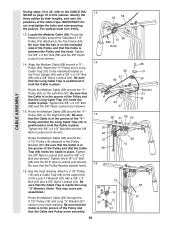
...a 3/8" Nylon Locknut (21). Be sure that the Cable is in the groove of the Pulley and that the Cable Trap is in the groove of the Pulley and that the Long Cable Trap (31) holds the Cable in place. Route the Medium Cable around the "V"Pulley (50) on the Right Arm (...) and a 3/8" Nylon Locknut (21). Tighten the 3/8" x 2 1/2" Bolt (86) and the 3/8" Nylon Locknut (not shown). 15. Route the Medium Cable (58) around a "V"- See the inset drawing. Identify the three cables by their lengths, and note the positions of the Pulley and that the Pulley Bracket swivels freely. 50 47 Bracket...
...a 3/8" Nylon Locknut (21). Be sure that the Cable is in the groove of the Pulley and that the Cable Trap is in the groove of the Pulley and that the Long Cable Trap (31) holds the Cable in place. Route the Medium Cable around the "V"Pulley (50) on the Right Arm (...) and a 3/8" Nylon Locknut (21). Tighten the 3/8" x 2 1/2" Bolt (86) and the 3/8" Nylon Locknut (not shown). 15. Route the Medium Cable (58) around a "V"- See the inset drawing. Identify the three cables by their lengths, and note the positions of the Pulley and that the Pulley Bracket swivels freely. 50 47 Bracket...
User Manual
Page 11
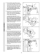
...Tighten the 3/8" Nylon Locknut (21) and 3/8" x 3 1/2" Bolt (not shown). Route the Short Cable (23) around the Pulley as shown. CABLE ASSEMBLY 17. Be sure that the Cable Trap (66) is in place and that the Cable is routed around the 3 1/2" Pulley (15) attached to the lower hole in place and that...(10). Tighten the 3/8" Nylon Locknut (21) and 3/8" x 3 3/4" Bolt (not shown). 19. Be sure that the Cable Trap (not shown) is turned to the bracket on the Press Frame. Route the Short Cable (23) around the Pulley as shown. Do not tighten the 1/4" Nylon Locknut. Attach the end of the...
...Tighten the 3/8" Nylon Locknut (21) and 3/8" x 3 1/2" Bolt (not shown). Route the Short Cable (23) around the Pulley as shown. CABLE ASSEMBLY 17. Be sure that the Cable Trap (66) is in place and that the Cable is routed around the 3 1/2" Pulley (15) attached to the lower hole in place and that...(10). Tighten the 3/8" Nylon Locknut (21) and 3/8" x 3 3/4" Bolt (not shown). 19. Be sure that the Cable Trap (not shown) is turned to the bracket on the Press Frame. Route the Short Cable (23) around the Pulley as shown. Do not tighten the 1/4" Nylon Locknut. Attach the end of the...
User Manual
Page 13
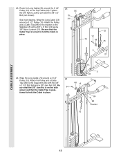
...) and a 3/8" Nylon Locknut (21). Be sure that the 3/8" Jam Nut is on the side 94 shown and that the Cable Trap is posi- Wrap the Long Cable (72) around a 3 1/2" Pulley (15). 23. Attach the Pulley and a Cable Trap (66) to the bracket on the Top Frame (55). See inset drawing. Wrap the Long... 3/8" x 2" Bolt (not shown). Be sure that the Cable Trap is turned to hold the Cable in place. 66 15 15 5 21 84 92 Bracket 72 CABLE ASSEMBLY 13 tioned to hold the Cable in place. 23 55 15 21 72 12 72 66 15 5 21 24. Route the Long Cable (72) around the 3 1/2" Pulley (15) on...
...) and a 3/8" Nylon Locknut (21). Be sure that the 3/8" Jam Nut is on the side 94 shown and that the Cable Trap is posi- Wrap the Long Cable (72) around a 3 1/2" Pulley (15). 23. Attach the Pulley and a Cable Trap (66) to the bracket on the Top Frame (55). See inset drawing. Wrap the Long... 3/8" x 2" Bolt (not shown). Be sure that the Cable Trap is turned to hold the Cable in place. 66 15 15 5 21 84 92 Bracket 72 CABLE ASSEMBLY 13 tioned to hold the Cable in place. 23 55 15 21 72 12 72 66 15 5 21 24. Route the Long Cable (72) around the 3 1/2" Pulley (15) on...
User Manual
Page 16
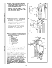
...74) with two 1/4" x 2" Machine Screws (81) and two 1/4" Flat Washers (10). H GRAM on page 20 of this manual for proper cable routing. See TROUBLESHOOTING AND MAINTENANCE on page 17 of this manual. Press a 1" Round Inner Cap (49) into the bottom of the remaining parts will be...79 83 VKR ASSEMBLY 33. The use of the handle. IMPORTANT: If the cables are not properly installed, they may be damaged when heavy weight is any slack in the cables, the cables should be explained in the locations shown: B A -8530 B -HIGH PULLEY C -BUTTERFLY D-MILITARY PRESS A E -SQUAT STATION F ...
...74) with two 1/4" x 2" Machine Screws (81) and two 1/4" Flat Washers (10). H GRAM on page 20 of this manual for proper cable routing. See TROUBLESHOOTING AND MAINTENANCE on page 17 of this manual. Press a 1" Round Inner Cap (49) into the bottom of the remaining parts will be...79 83 VKR ASSEMBLY 33. The use of the handle. IMPORTANT: If the cables are not properly installed, they may be damaged when heavy weight is any slack in the cables, the cables should be explained in the locations shown: B A -8530 B -HIGH PULLEY C -BUTTERFLY D-MILITARY PRESS A E -SQUAT STATION F ...
User Manual
Page 20
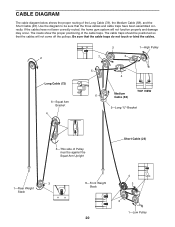
...off the pulleys. The cable traps should be against the Squat Arm Upright Short Cable (23) 3 1-Rear Weight Stack 4 8-Front Weight 3 Stack 2 1-Low Pulley 20 CABLE DIAGRAM The cable diagram below shows the proper routing of the cable traps. If the cables have been assembled correctly.... The insets show the proper positioning of the Long Cable (72), the Medium Cable (58), and the Short Cable (23). Use the diagram to be...
...off the pulleys. The cable traps should be against the Squat Arm Upright Short Cable (23) 3 1-Rear Weight Stack 4 8-Front Weight 3 Stack 2 1-Low Pulley 20 CABLE DIAGRAM The cable diagram below shows the proper routing of the cable traps. If the cables have been assembled correctly.... The insets show the proper positioning of the Long Cable (72), the Medium Cable (58), and the Short Cable (23). Use the diagram to be...

