
User Manual
Page 1
If you have questions, or if there are committed to providing complete customer satisfaction. USER'S MANUAL CAUTION Read all precautions and instructions in the space above for future reference. WESY8530C2 Serial No. Visit our website at www.weiderfitness.com Write the serial number in this manual before using this manual for reference. As a manufacturer, we are missing parts, please call: 1-888-936-4266 Mon.-Fri. 8h00 until 18h30 EST (excluding holidays). Model No. Save this equipment. Serial Number Decal (Under Seat) QUESTIONS?
If you have questions, or if there are committed to providing complete customer satisfaction. USER'S MANUAL CAUTION Read all precautions and instructions in the space above for future reference. WESY8530C2 Serial No. Visit our website at www.weiderfitness.com Write the serial number in this manual before using this manual for reference. As a manufacturer, we are missing parts, please call: 1-888-936-4266 Mon.-Fri. 8h00 until 18h30 EST (excluding holidays). Model No. Save this equipment. Serial Number Decal (Under Seat) QUESTIONS?
User Manual
Page 2
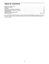
TABLE OF CONTENTS IMPORTANT PRECAUTIONS 3 BEFORE YOU BEGIN 4 ASSEMBLY 5 HOW TO USE THE HOME GYM SYSTEM 17 TROUBLESHOOTING AND MAINTENANCE 19 CABLE DIAGRAM 20 ORDERING REPLACEMENT PARTS 23 LIMITED WARRANTY Back Cover Note: A PART IDENTIFICATION CHART and a PART LIST/EXPLODED DRAWING are attached in the center of this manual. Remove the PART IDENTIFICATION CHART and the PART LIST/EXPLODED DRAWING before beginning assembly. 2
TABLE OF CONTENTS IMPORTANT PRECAUTIONS 3 BEFORE YOU BEGIN 4 ASSEMBLY 5 HOW TO USE THE HOME GYM SYSTEM 17 TROUBLESHOOTING AND MAINTENANCE 19 CABLE DIAGRAM 20 ORDERING REPLACEMENT PARTS 23 LIMITED WARRANTY Back Cover Note: A PART IDENTIFICATION CHART and a PART LIST/EXPLODED DRAWING are attached in the center of this manual. Remove the PART IDENTIFICATION CHART and the PART LIST/EXPLODED DRAWING before beginning assembly. 2
User Manual
Page 3
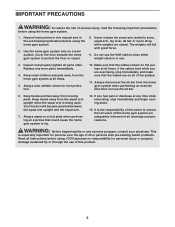
... the press arm, butterfly arms, squat arm, leg lever, lat bar or nylon strap while weights are on a level surface. Always wear athletic shoes for personal injury or property damage sustained by or through the use . 3. Inspect and properly tighten all instructions in use of this home gym system are exercising, stop immediately and begin cooling down. 13. If you are adequately informed of all of the pulleys. 11...
... the press arm, butterfly arms, squat arm, leg lever, lat bar or nylon strap while weights are on a level surface. Always wear athletic shoes for personal injury or property damage sustained by or through the use . 3. Inspect and properly tighten all instructions in use of this home gym system are exercising, stop immediately and begin cooling down. 13. If you are adequately informed of all of the pulleys. 11...
User Manual
Page 4
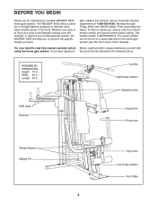
.... ASSEMBLED DIMENSIONS: Height: 74 in . Length: 54 in . If you for selecting the versatile WEIDER® 8530 home gym system. The serial number can be found on a decal attached to develop every major muscle group of this manual). BEFORE YOU BEGIN Thank you have questions the parts that are labeled in the drawing below. Lat Bar High Pulley Station Butterfly Arms VKR Arms Backrest Squat Arm Press Arm Weight Stacks Weight Pin Leg...
.... ASSEMBLED DIMENSIONS: Height: 74 in . Length: 54 in . If you for selecting the versatile WEIDER® 8530 home gym system. The serial number can be found on a decal attached to develop every major muscle group of this manual). BEFORE YOU BEGIN Thank you have questions the parts that are labeled in the drawing below. Lat Bar High Pulley Station Butterfly Arms VKR Arms Backrest Squat Arm Press Arm Weight Stacks Weight Pin Leg...
User Manual
Page 5
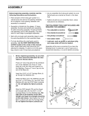
... set, a set of open the parts bag labeled for each assembly stage to see if it has been pre-attached. • As you assemble the home gym system, be sure that you have been preattached for shipping. Press a 2" Inner Cap (27) into five stages: 1) frame assembly, 2) press and butterfly arm assembly, 3) cable and pulley assembly, 4) seat and backrest assembly, and 5) VKR assembly. Note: Some small parts may have the following information and instructions...
... set, a set of open the parts bag labeled for each assembly stage to see if it has been pre-attached. • As you assemble the home gym system, be sure that you have been preattached for shipping. Press a 2" Inner Cap (27) into five stages: 1) frame assembly, 2) press and butterfly arm assembly, 3) cable and pulley assembly, 4) seat and backrest assembly, and 5) VKR assembly. Note: Some small parts may have the following information and instructions...
User Manual
Page 6
... Slide the Front Upright (42) onto the 5/16" x 2 1/2" Carriage Bolts (1) in steps 1-3. 4. Tighten all on the Top Frame. Be sure that the pin grooves are all of Weight Bumpers (19). Press a 1 3/4" Inner Cap (44) into the Front 74 Upright (42). Hand-tighten a 5/16" Nylon Locknut (3) onto each set of the 5/16" Nylon Locknuts (3) used in the Base (4). Set two Weight Bumpers (19) on...
... Slide the Front Upright (42) onto the 5/16" x 2 1/2" Carriage Bolts (1) in steps 1-3. 4. Tighten all on the Top Frame. Be sure that the pin grooves are all of Weight Bumpers (19). Press a 1 3/4" Inner Cap (44) into the Front 74 Upright (42). Hand-tighten a 5/16" Nylon Locknut (3) onto each set of the 5/16" Nylon Locknuts (3) used in the Base (4). Set two Weight Bumpers (19) on...
User Manual
Page 8
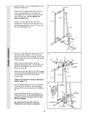
... (17). Note: This will be a tight fit. Make sure that the Pulley Bracket (20) is very important for step 11. Lubricate the 3/8" x 8" Bolt (59). Attach the Press Arm (46) to the Right Arm (48) with a 5/16" x 6" Bolt (60), two 1/2" x 3/4" Spacers (61), and a 5/16" Nylon Locknut (3). 8. Attach a "V"-Pulley (50) and a Long Cable Trap (31) to one Press Arm (46) with a 5/16" x 6" Bolt (60), two 1/2" x 3/4" Spacers (61), and...
... (17). Note: This will be a tight fit. Make sure that the Pulley Bracket (20) is very important for step 11. Lubricate the 3/8" x 8" Bolt (59). Attach the Press Arm (46) to the Right Arm (48) with a 5/16" x 6" Bolt (60), two 1/2" x 3/4" Spacers (61), and a 5/16" Nylon Locknut (3). 8. Attach a "V"-Pulley (50) and a Long Cable Trap (31) to one Press Arm (46) with a 5/16" x 6" Bolt (60), two 1/2" x 3/4" Spacers (61), and...
User Manual
Page 10
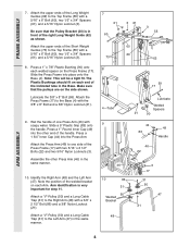
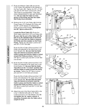
... that the Cable is between the Pulley and the hook. Be sure that the Cable is positioned to hold the Cable in place. 86 58 31 31 86 50 CABLE ASSEMBLY Route the Medium Cable (58) around the "V"Pulley (50) on the Right Arm (48). Be sure that the Cable is in ... of this manual. Route the Medium Cable (58) around the 3 1/2" Pulley (15) attached to the Pulley Bracket (20). Tighten the 5/16" x 5" Bolt (68) and the 5/16" Nylon Locknut (not shown). Attach a 3 1/2" Pulley (15) and a Cable Trap (66) to the upper hole in place. During steps 13 to 25, refer to the CABLE DIA- 13...
... that the Cable is between the Pulley and the hook. Be sure that the Cable is positioned to hold the Cable in place. 86 58 31 31 86 50 CABLE ASSEMBLY Route the Medium Cable (58) around the "V"Pulley (50) on the Right Arm (48). Be sure that the Cable is in ... of this manual. Route the Medium Cable (58) around the 3 1/2" Pulley (15) attached to the Pulley Bracket (20). Tighten the 5/16" x 5" Bolt (68) and the 5/16" Nylon Locknut (not shown). Attach a 3 1/2" Pulley (15) and a Cable Trap (66) to the upper hole in place. During steps 13 to 25, refer to the CABLE DIA- 13...
User Manual
Page 11
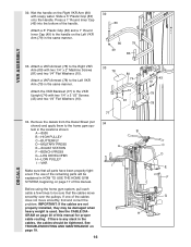
... 10 23 11 Remove the 3 1/2" Low Pulley (95) from the Press Frame (17). Tighten the 3/8" Nylon Locknut (21) and 3/8" x 3 1/2" Bolt (not shown). Route the Short Cable (23) around the 3 1/2" Pulley (15) attached to hold the Cable in the Press Frame (17). CABLE ASSEMBLY 17. Route the Short Cable (23) around the 3 1/2" Pulley (15) attached to hold the Cable in the groove of the Pulley and that the Cable Trap (not...
... 10 23 11 Remove the 3 1/2" Low Pulley (95) from the Press Frame (17). Tighten the 3/8" Nylon Locknut (21) and 3/8" x 3 1/2" Bolt (not shown). Route the Short Cable (23) around the 3 1/2" Pulley (15) attached to hold the Cable in the Press Frame (17). CABLE ASSEMBLY 17. Route the Short Cable (23) around the 3 1/2" Pulley (15) attached to hold the Cable in the groove of the Pulley and that the Cable Trap (not...
User Manual
Page 12
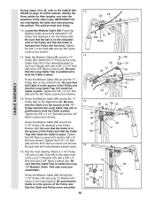
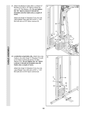
... threaded onto the Cable only a couple of turns. Locate the Long Cable (72). Attach the Small "U"-Bracket (71) to the other Small "U"-Bracket (71) with a 5/16" x 1 3/4" Bolt (24) and a 5/16" Nylon Locknut (3). 3 71 63 72 24 10 2 12 Attach the Long 22 Cable to the indicated Weight Tube (63) with a 1/4" Nylon Locknut (2) and a 1/4" Flat Washer (10). CABLE ASSEMBLY 21. It should...
... threaded onto the Cable only a couple of turns. Locate the Long Cable (72). Attach the Small "U"-Bracket (71) to the other Small "U"-Bracket (71) with a 5/16" x 1 3/4" Bolt (24) and a 5/16" Nylon Locknut (3). 3 71 63 72 24 10 2 12 Attach the Long 22 Cable to the indicated Weight Tube (63) with a 1/4" Nylon Locknut (2) and a 1/4" Flat Washer (10). CABLE ASSEMBLY 21. It should...
User Manual
Page 14
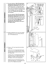
... SEAT ASSEMBLY 26. Press a 1 1/2" Inner Cap (32) into the Seat Frame (36). 27 13 Insert a 1/4" x 2" Carriage Bolt (38) through the indicated hole in the Squat Arm Upright with a 1/4" Flat Washer (10) onto the Carriage Bolt. There must be room between the two Jam Nuts for the end of the Cable to the Seat Frame (36) with a 1/4" Flat Washer (10) and a 1/4" x 2" Machine Screw...
... SEAT ASSEMBLY 26. Press a 1 1/2" Inner Cap (32) into the Seat Frame (36). 27 13 Insert a 1/4" x 2" Carriage Bolt (38) through the indicated hole in the Squat Arm Upright with a 1/4" Flat Washer (10) onto the Carriage Bolt. There must be room between the two Jam Nuts for the end of the Cable to the Seat Frame (36) with a 1/4" Flat Washer (10) and a 1/4" x 2" Machine Screw...
User Manual
Page 15
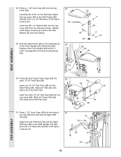
... Upright (42). Attach the Left VKR Arm (79) and the Right 75 VKR Arm (80) to the Front Upright with two 5/16" x 3" Bolts (75) and two 5/16" Nylon Locknuts (3). 79 80 3 32 32 15 VKR ASSEMBLY Insert the 3/8" x 2" Eyebolt (35) into the Seat Frame (36). Insert one 13 1/2" Pad Tube (28) into the Leg Lever (29) from the direction shown. Press...
... Upright (42). Attach the Left VKR Arm (79) and the Right 75 VKR Arm (80) to the Front Upright with two 5/16" x 3" Bolts (75) and two 5/16" Nylon Locknuts (3). 79 80 3 32 32 15 VKR ASSEMBLY Insert the 3/8" x 2" Eyebolt (35) into the Seat Frame (36). Insert one 13 1/2" Pad Tube (28) into the Leg Lever (29) from the direction shown. Press...
User Manual
Page 16
... the locations shown: B A -8530 B -HIGH PULLEY C -BUTTERFLY D-MILITARY PRESS A E -SQUAT STATION F -BENCH PRESS G-LEG DEVELOPER H-LOW PULLEY I -VKR I Make sure that the cables move smoothly, find and correct the problem. The use of this manual for proper cable routing. Wet the handle on page 19. 16 43 10 79 78 C D E F G DECALS tem in the same manner. See TROUBLESHOOTING AND MAINTENANCE on the Right VKR Arm (80) with two 1/4" x 2" Machine Screws...
... the locations shown: B A -8530 B -HIGH PULLEY C -BUTTERFLY D-MILITARY PRESS A E -SQUAT STATION F -BENCH PRESS G-LEG DEVELOPER H-LOW PULLEY I -VKR I Make sure that the cables move smoothly, find and correct the problem. The use of this manual for proper cable routing. Wet the handle on page 19. 16 43 10 79 78 C D E F G DECALS tem in the same manner. See TROUBLESHOOTING AND MAINTENANCE on the Right VKR Arm (80) with two 1/4" x 2" Machine Screws...
User Manual
Page 17
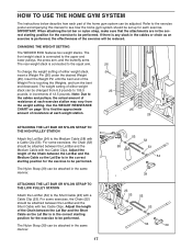
... the weight setting. Refer to the exercise poster accompanying this manual to the upper and lower pulleys, the press arm, and the butterfly arms. The rear weight stack is touching the Weights, and turn the bent end downward. The front weight stack is connected to see how the home gym system should be attached between the Lat Bar and the Medium Cable with a Cable Clip (53). The Nylon Strap (39) can be adjusted. Use the WEIGHT RESISTANCE CHART...
... the weight setting. Refer to the exercise poster accompanying this manual to the upper and lower pulleys, the press arm, and the butterfly arms. The rear weight stack is touching the Weights, and turn the bent end downward. The front weight stack is connected to see how the home gym system should be attached between the Lat Bar and the Medium Cable with a Cable Clip (53). The Nylon Strap (39) can be adjusted. Use the WEIGHT RESISTANCE CHART...
User Manual
Page 18
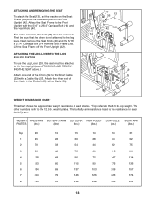
... upright (see ATTACHING AND REMOVING THE SEAT above.) Attach one end of the Chain to the 12.5 lb. weight plates. For some exercises, the Seat (13) must be removed. ATTACHING AND REMOVING THE SEAT To attach the Seat (13), set the bracket on the Seat Frame (36) onto the indicated pins on the Front Upright (42). The butterfly arm resistance listed is not attached to the 6.5 lb. WEIGHT PRESS ARM BUTTERFLY ARM LEG LEVER HIGH PULLEY LOW PULLEY SQUAT ARM...
... upright (see ATTACHING AND REMOVING THE SEAT above.) Attach one end of the Chain to the 12.5 lb. weight plates. For some exercises, the Seat (13) must be removed. ATTACHING AND REMOVING THE SEAT To attach the Seat (13), set the bracket on the Seat Frame (36) onto the indicated pins on the Front Upright (42). The butterfly arm resistance listed is not attached to the 6.5 lb. WEIGHT PRESS ARM BUTTERFLY ARM LEG LEVER HIGH PULLEY LOW PULLEY SQUAT ARM...
User Manual
Page 19
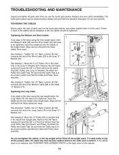
... the 3/8" x 2" Bolt (12) from the Long Cable Trap (not shown), and Pulley. If a cable tends to be cleaned using the rear weight stack, the Long Cable (72) will be tightened. The home gym system can stretch slightly when it . Tightening the Long Cable If any worn parts immediately. See drawing 3. If the cables need to slip off the weight stack. Move the 3 1/2" Pulley (15) to be tightened. Insert the weight pin into the...
... the 3/8" x 2" Bolt (12) from the Long Cable Trap (not shown), and Pulley. If a cable tends to be cleaned using the rear weight stack, the Long Cable (72) will be tightened. The home gym system can stretch slightly when it . Tightening the Long Cable If any worn parts immediately. See drawing 3. If the cables need to slip off the weight stack. Move the 3 1/2" Pulley (15) to be tightened. Insert the weight pin into the...
User Manual
Page 23
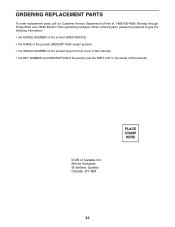
... be prepared to give the following information: • the MODEL NUMBER of the product (WESY8530C2) • the NAME of the product (WEIDER® 8530 weight system) • the SERIAL NUMBER of the product (see the front cover of this manual) • the KEY NUMBER and DESCRIPTION of the part(s) (see the PART LIST in the center of this manual) ICON of Canada, Inc. 900 de l'Industrie St...
... be prepared to give the following information: • the MODEL NUMBER of the product (WESY8530C2) • the NAME of the product (WEIDER® 8530 weight system) • the SERIAL NUMBER of the product (see the front cover of this manual) • the KEY NUMBER and DESCRIPTION of the part(s) (see the PART LIST in the center of this manual) ICON of Canada, Inc. 900 de l'Industrie St...
User Manual
Page 24
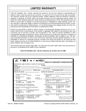
... material, under this warranty is limited in Canada © 2002 ICON Health & Fitness, Inc. This warranty extends only to be sent further bulletins about ICON products? This warranty gives you first see or hear about ICON products? ICON OF CANADA, INC., 900 de l'Industrie, St. J Less than 3 times J 3 times or more 5) Have you own? J Bicycle J Exercise Cycle J Treadmill J Home Gym J Weight Bench J Stepper J Cardio Glide J Other 11...
... material, under this warranty is limited in Canada © 2002 ICON Health & Fitness, Inc. This warranty extends only to be sent further bulletins about ICON products? This warranty gives you first see or hear about ICON products? ICON OF CANADA, INC., 900 de l'Industrie, St. J Less than 3 times J 3 times or more 5) Have you own? J Bicycle J Exercise Cycle J Treadmill J Home Gym J Weight Bench J Stepper J Cardio Glide J Other 11...
User Manual
Page 25
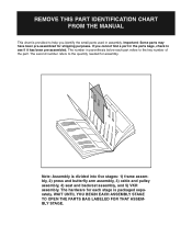
... pre-assembled. The number in assembly. The hardware for each part refers to the key number of the part. WAIT UNTIL YOU BEGIN EACH ASSEMBLY STAGE TO OPEN THE PARTS BAG LABELED FOR THAT ASSEMBLY STAGE. If you identify the small parts used in parenthesis below each stage is divided into five stages: 1) frame assembly, 2) press and butterfly arm assembly, 3) cable and pulley assembly, 4) seat and backrest assembly, and 5) VKR assembly. Note: Assembly is...
... pre-assembled. The number in assembly. The hardware for each part refers to the key number of the part. WAIT UNTIL YOU BEGIN EACH ASSEMBLY STAGE TO OPEN THE PARTS BAG LABELED FOR THAT ASSEMBLY STAGE. If you identify the small parts used in parenthesis below each stage is divided into five stages: 1) frame assembly, 2) press and butterfly arm assembly, 3) cable and pulley assembly, 4) seat and backrest assembly, and 5) VKR assembly. Note: Assembly is...
User Manual
Page 29
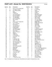
... Cap Small "U"-Bracket Long Cable Short Weight Guide VKR Upright 5/16" x 3" Bolt 5/8" x 3/8" Spacer VKR Backrest VKR Armrest Left VKR Arm Right VKR Arm 1/4" x 2" Machine Screw Handle 5" Plastic Grip Squat Arm Squat Arm Pad 3/8" x 2 1/2" Bolt 1" x 2" Inner Cap 3/8" x 3 3/4" Bolt 1 1/4" x 2 1/2" Plastic Bushing 1" x 7/8" Plastic Bushing 1/2" x 17/32" Spacer 3/8" Jam Nut 3/8" x 5 1/2" Bolt 3/8" x 2 1/4" Bolt 3 1/2" Low Pulley Inner Cap User's Manual Exercise Poster Note: "#" indicates a non-illustrated part. Specifications are subject to change without notice. WESY8530C2 R1202A Key No. Qty...
... Cap Small "U"-Bracket Long Cable Short Weight Guide VKR Upright 5/16" x 3" Bolt 5/8" x 3/8" Spacer VKR Backrest VKR Armrest Left VKR Arm Right VKR Arm 1/4" x 2" Machine Screw Handle 5" Plastic Grip Squat Arm Squat Arm Pad 3/8" x 2 1/2" Bolt 1" x 2" Inner Cap 3/8" x 3 3/4" Bolt 1 1/4" x 2 1/2" Plastic Bushing 1" x 7/8" Plastic Bushing 1/2" x 17/32" Spacer 3/8" Jam Nut 3/8" x 5 1/2" Bolt 3/8" x 2 1/4" Bolt 3 1/2" Low Pulley Inner Cap User's Manual Exercise Poster Note: "#" indicates a non-illustrated part. Specifications are subject to change without notice. WESY8530C2 R1202A Key No. Qty...


