
User Manual
Page 2
TABLE OF CONTENTS IMPORTANT PRECAUTIONS 3 BEFORE YOU BEGIN 4 ASSEMBLY 5 HOW TO USE THE HOME GYM SYSTEM 17 TROUBLESHOOTING AND MAINTENANCE 19 CABLE DIAGRAM 20 ORDERING REPLACEMENT PARTS 23 LIMITED WARRANTY Back Cover Note: A PART IDENTIFICATION CHART and a PART LIST/EXPLODED DRAWING are attached in the center of this manual. Remove the PART IDENTIFICATION CHART and the PART LIST/EXPLODED DRAWING before beginning assembly. 2
TABLE OF CONTENTS IMPORTANT PRECAUTIONS 3 BEFORE YOU BEGIN 4 ASSEMBLY 5 HOW TO USE THE HOME GYM SYSTEM 17 TROUBLESHOOTING AND MAINTENANCE 19 CABLE DIAGRAM 20 ORDERING REPLACEMENT PARTS 23 LIMITED WARRANTY Back Cover Note: A PART IDENTIFICATION CHART and a PART LIST/EXPLODED DRAWING are attached in the center of this manual. Remove the PART IDENTIFICATION CHART and the PART LIST/EXPLODED DRAWING before beginning assembly. 2
User Manual
Page 3
...the home gym system when performing an exercise that could become pinched between the squat arm upright and the squat arm. 7. If the cables bind while you feel pain or dizziness at all warnings and precautions. IMPORTANT PRECAUTIONS WARNING: To reduce the risk of serious injury, ... parts immediately. 4. WARNING: Before beginning this product. 3 Read all parts often. Replace any exercise program, consult your physician. Make sure that the cables remain on a foot plate when performing an exercise that does not use . 3. Cover the floor beneath the home gym system to tip. 12. ...
...the home gym system when performing an exercise that could become pinched between the squat arm upright and the squat arm. 7. If the cables bind while you feel pain or dizziness at all warnings and precautions. IMPORTANT PRECAUTIONS WARNING: To reduce the risk of serious injury, ... parts immediately. 4. WARNING: Before beginning this product. 3 Read all parts often. Replace any exercise program, consult your physician. Make sure that the cables remain on a foot plate when performing an exercise that does not use . 3. Cover the floor beneath the home gym system to tip. 12. ...
User Manual
Page 5
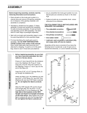
.... 1 56 High Side 74 3 27 51 11 8 3 5 1 51 1 3 4 27 5 FRAME ASSEMBLY 1. Press a 2" Inner Cap (27) into five stages: 1) frame assembly, 2) press and butterfly arm assembly, 3) cable and pulley assembly, 4) seat and backrest assembly, and 5) VKR assembly. The high side of the Base (4). do otherwise. Note: Some small parts may have the...
.... 1 56 High Side 74 3 27 51 11 8 3 5 1 51 1 3 4 27 5 FRAME ASSEMBLY 1. Press a 2" Inner Cap (27) into five stages: 1) frame assembly, 2) press and butterfly arm assembly, 3) cable and pulley assembly, 4) seat and backrest assembly, and 5) VKR assembly. The high side of the Base (4). do otherwise. Note: Some small parts may have the...
User Manual
Page 8
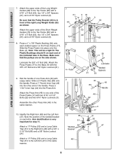
... the Press Frame (17). Press a 1" Round Inner Cap (49) into the other Press Arm (46) in the Base. FRAME ASSEMBLY 7. Attach a "V"-Pulley (50) and a Long Cable Trap (31) to the Right Arm (48) with soapy water. Note: This will be a tight fit. The Plastic Bushings should fit on the side shown... 83 46 22 49 Handle 46 10 86 31 50 Welded Bracket 48 3 17 31 50 47 21 ARM ASSEMBLY 8 Attach a "V"-Pulley (50) and a Long Cable Trap (31) to the Left Arm (47) in front of the Press Frame (17) with the 3/8" x 8" Bolt and a 3/8" Nylon Locknut (21). 9.
... the Press Frame (17). Press a 1" Round Inner Cap (49) into the other Press Arm (46) in the Base. FRAME ASSEMBLY 7. Attach a "V"-Pulley (50) and a Long Cable Trap (31) to the Right Arm (48) with soapy water. Note: This will be a tight fit. The Plastic Bushings should fit on the side shown... 83 46 22 49 Handle 46 10 86 31 50 Welded Bracket 48 3 17 31 50 47 21 ARM ASSEMBLY 8 Attach a "V"-Pulley (50) and a Long Cable Trap (31) to the Left Arm (47) in front of the Press Frame (17) with the 3/8" x 8" Bolt and a 3/8" Nylon Locknut (21). 9.
User Manual
Page 10
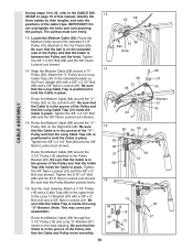
...sure that the ball is on the indicated side of this manual. Be sure that the Cable is in the groove of the "V"Pulley and that the Long Cable Trap (31) is positioned to hold the Cable in the inset drawing. See the inset drawing. The pulleys must turn freely. 58 55...2 1/2" Bolt (86) and the 3/8" Nylon Locknut (not shown). Tighten the 5/16" x 5" Bolt (68) and the 5/16" Nylon Locknut (not shown). Be sure that the Cable is in place. Wrap the Medium Cable (58) around the "V"Pulley (50) on the Front Upright (42) with a 3/8" x 2" Bolt (12) and a 3/8" Nylon Locknut (21). Route the Medium...
...sure that the ball is on the indicated side of this manual. Be sure that the Cable is in the groove of the "V"Pulley and that the Long Cable Trap (31) is positioned to hold the Cable in the inset drawing. See the inset drawing. The pulleys must turn freely. 58 55...2 1/2" Bolt (86) and the 3/8" Nylon Locknut (not shown). Tighten the 5/16" x 5" Bolt (68) and the 5/16" Nylon Locknut (not shown). Be sure that the Cable is in place. Wrap the Medium Cable (58) around the "V"Pulley (50) on the Front Upright (42) with a 3/8" x 2" Bolt (12) and a 3/8" Nylon Locknut (21). Route the Medium...
User Manual
Page 11
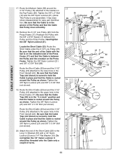
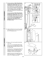
... the 3/8" Nylon Locknut (21) and 3/8" x 3 3/4" Bolt (not shown). 19. Be sure that the Cable is in the Press Frame (17). CABLE ASSEMBLY 17. Route the Short Cable under the 3 1/2" Low Pulley (95). Be sure that the Cable is turned to the Long "U"-Bracket (57) with the 5/8" x 9/16" Spacer (7) between the Pulley and... (42). Remove the 3 1/2" Low Pulley (95) from the Press Frame (17). Locate the Short Cable (23). Be sure that the Cable Trap (66) is in the "3 o'clock" position and that the Cable is pre-assembled. Attach the end of turns. 17 55 15 12 Bracket 58 21 18 15 21...
... the 3/8" Nylon Locknut (21) and 3/8" x 3 3/4" Bolt (not shown). 19. Be sure that the Cable is in the Press Frame (17). CABLE ASSEMBLY 17. Route the Short Cable under the 3 1/2" Low Pulley (95). Be sure that the Cable is turned to the Long "U"-Bracket (57) with the 5/8" x 9/16" Spacer (7) between the Pulley and... (42). Remove the 3 1/2" Low Pulley (95) from the Press Frame (17). Locate the Short Cable (23). Be sure that the Cable Trap (66) is in the "3 o'clock" position and that the Cable is pre-assembled. Attach the end of turns. 17 55 15 12 Bracket 58 21 18 15 21...
User Manual
Page 12
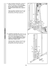
... a couple of turns. It should be threaded onto the Cable only a couple of turns. Locate the Long Cable (72). Attach the Medium Cable (58) to the indicated Weight Tube (63) with a 1/4" Nylon Locknut (2) and a 1/4" Flat Washer (10). Do not tighten the 1/4" ...Nylon Locknut (3). 58 71 24 3 63 10 2 22. Do not tighten the 1/4" Nylon Locknut. Attach the Long 22 Cable to the indicated Weight Tube (63) with a 1/4" Nylon Locknut (2) and a 1/4" Flat Washer (10). CABLE ASSEMBLY 21. Attach the Small "U"-Bracket (71) to the other Small "U"-Bracket (71) with a 5/16" x 1...
... a couple of turns. It should be threaded onto the Cable only a couple of turns. Locate the Long Cable (72). Attach the Medium Cable (58) to the indicated Weight Tube (63) with a 1/4" Nylon Locknut (2) and a 1/4" Flat Washer (10). Do not tighten the 1/4" ...Nylon Locknut (3). 58 71 24 3 63 10 2 22. Do not tighten the 1/4" Nylon Locknut. Attach the Long 22 Cable to the indicated Weight Tube (63) with a 1/4" Nylon Locknut (2) and a 1/4" Flat Washer (10). CABLE ASSEMBLY 21. Attach the Small "U"-Bracket (71) to the other Small "U"-Bracket (71) with a 5/16" x 1...
User Manual
Page 13
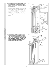
...Nylon Locknut (21). See inset drawing. Attach the Pulley and a Cable Trap (66) to hold the Cable in place. 66 15 15 5 21 84 92 Bracket 72 CABLE ASSEMBLY 13 Wrap the Long Cable (72) around a 3 1/2" Pulley (15). Be sure that the Cable Trap is turned to the bracket on the Stabilizer (5) with the... 3/8" x 2 1/4" Bolt (94) and a 3/8" Jam Nut (92). Be sure that the Cable Trap is on the Top Frame (55). Route the Long Cable (72) around the 3 1/2" Pulley (15) on the side 94 shown and that the 3/8" Jam Nut is posi- Attach the Pulley...
...Nylon Locknut (21). See inset drawing. Attach the Pulley and a Cable Trap (66) to hold the Cable in place. 66 15 15 5 21 84 92 Bracket 72 CABLE ASSEMBLY 13 Wrap the Long Cable (72) around a 3 1/2" Pulley (15). Be sure that the Cable Trap is turned to the bracket on the Stabilizer (5) with the... 3/8" x 2 1/4" Bolt (94) and a 3/8" Jam Nut (92). Be sure that the Cable Trap is on the Top Frame (55). Route the Long Cable (72) around the 3 1/2" Pulley (15) on the side 94 shown and that the 3/8" Jam Nut is posi- Attach the Pulley...
User Manual
Page 14
... in the Seat Frame (36). Do not tighten the second Jam Nut. Thread another 3/8" Jam Nut (92) onto the Bolt. Attach the "V"-Pulley and a Long Cable Trap (31) to the top hole in the Seat Plate (37). Tighten a 1/4" Nylon Locknut (2) with the 3/8" x 5" Bolt (67), the 5/8" x 3/8" Spacer (76...), a 3/8" Flat Washer (9), and a 3/8" Nylon Locknut (21). CABLE ASSEMBLY 25. See inset drawing B. Attach the Seat Plate to pivot. 25 50 72 Insets show view from the other side A 21 9 76 56 72...
... in the Seat Frame (36). Do not tighten the second Jam Nut. Thread another 3/8" Jam Nut (92) onto the Bolt. Attach the "V"-Pulley and a Long Cable Trap (31) to the top hole in the Seat Plate (37). Tighten a 1/4" Nylon Locknut (2) with the 3/8" x 5" Bolt (67), the 5/8" x 3/8" Spacer (76...), a 3/8" Flat Washer (9), and a 3/8" Nylon Locknut (21). CABLE ASSEMBLY 25. See inset drawing B. Attach the Seat Plate to pivot. 25 50 72 Insets show view from the other side A 21 9 76 56 72...
User Manual
Page 16
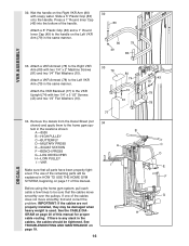
...them to the Left VKR Arm (79) in the locations shown: B A -8530 B -HIGH PULLEY C -BUTTERFLY D-MILITARY PRESS A E -SQUAT STATION F -BENCH PRESS G-LEG DEVELOPER H-LOW PULLEY I -VKR I Make sure that the cables move smoothly, find and correct the problem. tem in the same manner. Before using... 1/4" Flat Washers (10). H GRAM on page 17 of this manual. Press a 1" Round Inner Cap (49) into the bottom of the cables does not move smoothly over the pulleys. See TROUBLESHOOTING AND MAINTENANCE on the Left VKR Arm (79) in HOW TO USE THE HOME GYM SYSTEM...
...them to the Left VKR Arm (79) in the locations shown: B A -8530 B -HIGH PULLEY C -BUTTERFLY D-MILITARY PRESS A E -SQUAT STATION F -BENCH PRESS G-LEG DEVELOPER H-LOW PULLEY I -VKR I Make sure that the cables move smoothly, find and correct the problem. tem in the same manner. Before using... 1/4" Flat Washers (10). H GRAM on page 17 of this manual. Press a 1" Round Inner Cap (49) into the bottom of the cables does not move smoothly over the pulleys. See TROUBLESHOOTING AND MAINTENANCE on the Left VKR Arm (79) in HOW TO USE THE HOME GYM SYSTEM...
User Manual
Page 17
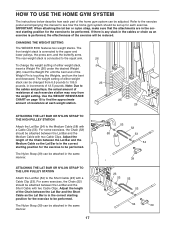
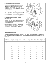
...be attached between the Lat Bar and the Short Cable so the Lat Bar is connected to be performed. Adjust the length of either weight stack, insert a Weight Pin (26) under the desired Weight (25). CHANGING THE WEIGHT SETTING The WEIDER 8530 features two weight stacks. The weight setting of ...the Chain between the Lat Bar and the Medium Cable with a Cable Clip (53). ATTACHING THE LAT BAR OR NYLON STRAP TO THE LOW PULLEY STATION Attach the...
...be attached between the Lat Bar and the Short Cable so the Lat Bar is connected to be performed. Adjust the length of either weight stack, insert a Weight Pin (26) under the desired Weight (25). CHANGING THE WEIGHT SETTING The WEIDER 8530 features two weight stacks. The weight setting of ...the Chain between the Lat Bar and the Medium Cable with a Cable Clip (53). ATTACHING THE LAT BAR OR NYLON STRAP TO THE LOW PULLEY STATION Attach the...
User Manual
Page 18
... (29), the seat must be sure that the chain is the resistance for each station. Attach the other numbers refer to the Front Upright with a Cable Clip (53). top weight. Next, remove the Seat Knob (40) and the 5/16" x 2 3/4" Carriage Bolt (14) from the Seat Frame (36). Attach the Seat ... Seat (13) must be attached to the front upright (see ATTACHING AND REMOVING THE SEAT above.) Attach one end of the Chain to the Short Cable (23) with the 5/16" x 2 3/4" Carriage Bolt (14) and the Seat Knob (40). weight plates. First, be removed. ATTACHING AND REMOVING THE SEAT To attach ...
... (29), the seat must be sure that the chain is the resistance for each station. Attach the other numbers refer to the Front Upright with a Cable Clip (53). top weight. Next, remove the Seat Knob (40) and the 5/16" x 2 3/4" Carriage Bolt (14) from the Seat Frame (36). Attach the Seat ... Seat (13) must be attached to the front upright (see ATTACHING AND REMOVING THE SEAT above.) Attach one end of the Chain to the Short Cable (23) with the 5/16" x 2 3/4" Carriage Bolt (14) and the Seat Knob (40). weight plates. First, be removed. ATTACHING AND REMOVING THE SEAT To attach ...
User Manual
Page 19
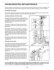
...cloth and mild non-abrasive detergent. Replace any slack is in the Long "U"-Bracket (57). Insert the weight pin into the middle of the Long Cable (72) to slip off the weight stack. Move the 3 1/2" Pulley (15) to be cleaned using the front weight stack, both the Medium... Cable (58) and the Short Cable (23) will be tightened. The home gym system can stretch slightly when it . Do not use the home gym system. TROUBLESHOOTING AND MAINTENANCE Inspect and...
...cloth and mild non-abrasive detergent. Replace any slack is in the Long "U"-Bracket (57). Insert the weight pin into the middle of the Long Cable (72) to slip off the weight stack. Move the 3 1/2" Pulley (15) to be cleaned using the front weight stack, both the Medium... Cable (58) and the Short Cable (23) will be tightened. The home gym system can stretch slightly when it . Do not use the home gym system. TROUBLESHOOTING AND MAINTENANCE Inspect and...
User Manual
Page 20
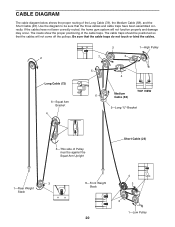
...the proper positioning of the Long Cable (72), the Medium Cable (58), and the Short Cable (23). Be sure that the three cables and cable traps have not been correctly routed, the home gym system will not come off the pulleys. If the cables have been assembled correctly. Use the... diagram to be sure that the cable traps do not touch or bind the cables. 2 1-High Pulley 2 7 3 Long Cable (72) 6-Squat Arm Bracket 4 5 6 4 Medium Cable (58) TOP VIEW 5-Long "U"-Bracket 5-This side ...
...the proper positioning of the Long Cable (72), the Medium Cable (58), and the Short Cable (23). Be sure that the three cables and cable traps have not been correctly routed, the home gym system will not come off the pulleys. If the cables have been assembled correctly. Use the... diagram to be sure that the cable traps do not touch or bind the cables. 2 1-High Pulley 2 7 3 Long Cable (72) 6-Squat Arm Bracket 4 5 6 4 Medium Cable (58) TOP VIEW 5-Long "U"-Bracket 5-This side ...
User Manual
Page 25
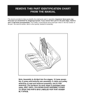
... the quantity needed for shipping purposes. The number in parenthesis below each stage is divided into five stages: 1) frame assembly, 2) press and butterfly arm assembly, 3) cable and pulley assembly, 4) seat and backrest assembly, and 5) VKR assembly. Note: Assembly is packaged separately. REMOVE THIS PART IDENTIFICATION CHART FROM THE MANUAL This chart...
... the quantity needed for shipping purposes. The number in parenthesis below each stage is divided into five stages: 1) frame assembly, 2) press and butterfly arm assembly, 3) cable and pulley assembly, 4) seat and backrest assembly, and 5) VKR assembly. Note: Assembly is packaged separately. REMOVE THIS PART IDENTIFICATION CHART FROM THE MANUAL This chart...
User Manual
Page 28
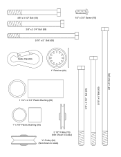
3/8" x 3 1/2" Bolt (16) 3/8" x 3 3/4" Bolt (88) 5/16" x 5" Bolt (68) 1/4" x 3/4" Screw (18) Cable Clip (53) 1" Retainer (69) 3/8" x 5 1/2" Bolt (93) 5/16" x 6" Bolt (60) 3/8" x 8" Bolt (59) 1 1/4" x 2 1/2" Plastic Bushing (89) 1" x 7/8" Plastic Bushing (90) 3 1/2" Pulley (15) (Not shown to scale) "V"-Pulley (50) (Not shown to scale)
3/8" x 3 1/2" Bolt (16) 3/8" x 3 3/4" Bolt (88) 5/16" x 5" Bolt (68) 1/4" x 3/4" Screw (18) Cable Clip (53) 1" Retainer (69) 3/8" x 5 1/2" Bolt (93) 5/16" x 6" Bolt (60) 3/8" x 8" Bolt (59) 1 1/4" x 2 1/2" Plastic Bushing (89) 1" x 7/8" Plastic Bushing (90) 3 1/2" Pulley (15) (Not shown to scale) "V"-Pulley (50) (Not shown to scale)

User Manual
Page 29
... Bolt Press Frame 1/4" x 3/4" Screw Weight Bumper Pulley Bracket 3/8" Nylon Locknut 5/16" x 2 1/2" Bolt Short Cable 5/16" x 1 3/4" Bolt Weight Weight Pin 2" Inner Cap 13 1/2" Pad Tube Leg Lever 6" Pad Long Cable Trap 1 1/2" Inner Cap 5/16" x 2 1/4" Bolt 3/4" Round Inner Cap 3/8" x 2" Eyebolt Seat Frame...89 2 90 2 91 2 92 2 93 1 94 1 95 1 96 2 # 1 # 1 Description "V"-Pulley 2" Outer Cap Chain Cable Clip Lat Bar Top Frame Squat Arm Upright Long "U"-Bracket Medium Cable 3/8" x 8" Bolt 5/16" x 6" Bolt 1/2" x 3/4" Spacer Long Weight Guide Weight Tube Weight Tube Bumper Top Weight...
... Bolt Press Frame 1/4" x 3/4" Screw Weight Bumper Pulley Bracket 3/8" Nylon Locknut 5/16" x 2 1/2" Bolt Short Cable 5/16" x 1 3/4" Bolt Weight Weight Pin 2" Inner Cap 13 1/2" Pad Tube Leg Lever 6" Pad Long Cable Trap 1 1/2" Inner Cap 5/16" x 2 1/4" Bolt 3/4" Round Inner Cap 3/8" x 2" Eyebolt Seat Frame...89 2 90 2 91 2 92 2 93 1 94 1 95 1 96 2 # 1 # 1 Description "V"-Pulley 2" Outer Cap Chain Cable Clip Lat Bar Top Frame Squat Arm Upright Long "U"-Bracket Medium Cable 3/8" x 8" Bolt 5/16" x 6" Bolt 1/2" x 3/4" Spacer Long Weight Guide Weight Tube Weight Tube Bumper Top Weight...


