
English Manual
Page 1
....weiderservice.com CAUTION Read all precautions and instructions in the space above for future reference. Write the serial number in this manual before using this manual for future reference. Save this equipment. Model No. If you have questions, or if a part is damaged or missing, PLEASE CONTACT OUR CUSTOMER SERVICE DEPARTMENT DIRECTLY. WESY2916.1 Serial No. CALL TOLL-FREE: 1-877-992-5999 Mon.-Fri...
....weiderservice.com CAUTION Read all precautions and instructions in the space above for future reference. Write the serial number in this manual before using this manual for future reference. Save this equipment. Model No. If you have questions, or if a part is damaged or missing, PLEASE CONTACT OUR CUSTOMER SERVICE DEPARTMENT DIRECTLY. WESY2916.1 Serial No. CALL TOLL-FREE: 1-877-992-5999 Mon.-Fri...

English Manual
Page 2
TABLE OF CONTENTS IMPORTANT PRECAUTIONS 3 BEFORE YOU BEGIN 4 PART IDENTIFICATION CHART 5 ASSEMBLY 8 ADJUSTMENTS 25 WEIGHT RESISTANCE CHART 27 CABLE DIAGRAM 28 MAINTENANCE 29 EXERCISE GUIDELINES 30 PART LIST 33 EXPLODED DRAWING 34 ORDERING REPLACEMENT PARTS Back Cover LIMITED WARRANTY Back Cover WEIDER is a registered trademark of ICON IP, Inc. 2
TABLE OF CONTENTS IMPORTANT PRECAUTIONS 3 BEFORE YOU BEGIN 4 PART IDENTIFICATION CHART 5 ASSEMBLY 8 ADJUSTMENTS 25 WEIGHT RESISTANCE CHART 27 CABLE DIAGRAM 28 MAINTENANCE 29 EXERCISE GUIDELINES 30 PART LIST 33 EXPLODED DRAWING 34 ORDERING REPLACEMENT PARTS Back Cover LIMITED WARRANTY Back Cover WEIDER is a registered trademark of ICON IP, Inc. 2
English Manual
Page 3
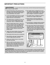
... for foot protection while exercising. 9. Read all cables at all precautions. 3. Always wear athletic shoes for home use the weight system with pre-existing health problems. Read all warnings on the front cover of this or any commercial, rental, or institutional setting. 4. Apply the decal in any exercise program, consult your physician. Keep the weight system indoors, away from moving parts. 7. IMPORTANT PRECAUTIONS WARNING...
... for foot protection while exercising. 9. Read all cables at all precautions. 3. Always wear athletic shoes for home use the weight system with pre-existing health problems. Read all warnings on the front cover of this or any commercial, rental, or institutional setting. 4. Apply the decal in any exercise program, consult your physician. Keep the weight system indoors, away from moving parts. 7. IMPORTANT PRECAUTIONS WARNING...
English Manual
Page 4
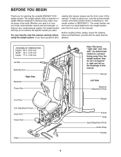
... Backrest Adjustment Knob Curl Pad Curl Adjustment Knob Leg Lever Foam Pad Chain Weight Frame Seat Seat Adjustment Knob Ankle Strap Handle 4 Whether your goal is WESY2916.1. ASSEMBLED DIMENSIONS: Height: 83 in. (210 cm) Width: 43 in. (109 cm) Depth: 77 in this manual). The serial number can be found on a decal attached to right and left on the drawings in . (196 cm) Lat Bar Butterfly Arm Right Side Backrest Press Arm...
... Backrest Adjustment Knob Curl Pad Curl Adjustment Knob Leg Lever Foam Pad Chain Weight Frame Seat Seat Adjustment Knob Ankle Strap Handle 4 Whether your goal is WESY2916.1. ASSEMBLED DIMENSIONS: Height: 83 in. (210 cm) Width: 43 in. (109 cm) Depth: 77 in this manual). The serial number can be found on a decal attached to right and left on the drawings in . (196 cm) Lat Bar Butterfly Arm Right Side Backrest Press Arm...
English Manual
Page 5
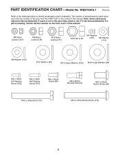
... not in the parts bag, check to identify small parts used in the center of this manual. Note: Some small parts may have been preattached. If a part is missing, call the toll-free number on the front cover of this manual. WESY2916.1 R0107A Refer to ...-tapping Screw (102) M4 x 16mm Self-tapping Screw (110) M6 x 16mm Screw (88) M8 x 22mm Shoulder Bolt (90) M10 x 20mm Button Screw (96) M10 x 70mm Bolt (113) M10 x 75mm Button Screw (118) 5 PART IDENTIFICATION CHART-Model No. The number in parentheses by each drawing is the key number of the part, from the PART LIST in assembly.
... not in the parts bag, check to identify small parts used in the center of this manual. Note: Some small parts may have been preattached. If a part is missing, call the toll-free number on the front cover of this manual. WESY2916.1 R0107A Refer to ...-tapping Screw (102) M4 x 16mm Self-tapping Screw (110) M6 x 16mm Screw (88) M8 x 22mm Shoulder Bolt (90) M10 x 20mm Button Screw (96) M10 x 70mm Bolt (113) M10 x 75mm Button Screw (118) 5 PART IDENTIFICATION CHART-Model No. The number in parentheses by each drawing is the key number of the part, from the PART LIST in assembly.
English Manual
Page 8
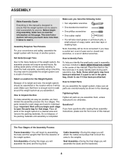
..., or a set of open the parts bag for each assembly step. If a part is designed to ensure that connect the arms to the weights. Questions? The parts needed for that form the skeleton of the weight system. Cable Assembly-During this stage you will attach the cables and pulleys that the weight system can be assembled successfully by deciding to make sure all parts are found in individual bags. ASSEMBLY Make Assembly Easier...
..., or a set of open the parts bag for each assembly step. If a part is designed to ensure that connect the arms to the weights. Questions? The parts needed for that form the skeleton of the weight system. Cable Assembly-During this stage you will attach the cables and pulleys that the weight system can be assembled successfully by deciding to make sure all parts are found in individual bags. ASSEMBLY Make Assembly Easier...

English Manual
Page 10
... Bolts (100), two M8 Washers (103), and two M8 Nylon Locknuts (78). Attach the Frame (9) to the Front Leg (10) with the pin holes on the Weight Tube is oriented as shown. Repeat this step clearly. 6 Slide the two Weight Bumpers (71) onto the Weight Guides (18). Attach the Frame (9) to the Upright (2) with the included grease packet. 4. Note: Some parts have been removed...
... Bolts (100), two M8 Washers (103), and two M8 Nylon Locknuts (78). Attach the Frame (9) to the Front Leg (10) with the pin holes on the Weight Tube is oriented as shown. Repeat this step clearly. 6 Slide the two Weight Bumpers (71) onto the Weight Guides (18). Attach the Frame (9) to the Upright (2) with the included grease packet. 4. Note: Some parts have been removed...

English Manual
Page 12
... bracket on the Lock Plate Pin to the Upright (2) with an M4 x 12mm Self-tapping Screw (102). 12. Do not tighten the Nylon Locknuts yet. Apply grease in the Leg Lever (12). Attach the Lock Plate (14) to the Butterfly Frame Brace (6) with the M8 x 69mm Shoulder Bolt (87), an M8 Washer ... Leg Lever (12). Attach the tether on the Front Leg. Attach the Butterfly Frame Brace (6) to the Front Leg (10) with two M8 x 80mm Bolts (100), two M8 Washers (103), and two M8 Nylon Locknuts (78). See the right inset drawing. Make sure the barrel of the Bolt Set is oriented as shown. Arm Assembly...
... bracket on the Lock Plate Pin to the Upright (2) with an M4 x 12mm Self-tapping Screw (102). 12. Do not tighten the Nylon Locknuts yet. Apply grease in the Leg Lever (12). Attach the Lock Plate (14) to the Butterfly Frame Brace (6) with the M8 x 69mm Shoulder Bolt (87), an M8 Washer ... Leg Lever (12). Attach the tether on the Front Leg. Attach the Butterfly Frame Brace (6) to the Front Leg (10) with two M8 x 80mm Bolts (100), two M8 Washers (103), and two M8 Nylon Locknuts (78). See the right inset drawing. Make sure the barrel of the Bolt Set is oriented as shown. Arm Assembly...

English Manual
Page 14
...tighten the Nylon Locknuts yet. 17 16 77 80 77 59 15 93 85 18. Attach the Left and Right Press Arms (15, 16) to the Right Press Arm (16) with the 90° bend 16 at the top as shown in step 17. 14 16 15 77 Grease 1 59 93 Repeat this step for the Left Press Arm... able to the Right Press Arm (16) with two M10 x 65mm Bolts (85), two M10 Washers (80), and two M10 Nylon Locknuts (77). Tighten the Nylon Locknuts (77) used in the inset drawing. Attach the Left Press Arm (15) to pivot freely. 16. Finish attaching the Press Arms with an M10 x 110mm Bolt (93), an 89....
...tighten the Nylon Locknuts yet. 17 16 77 80 77 59 15 93 85 18. Attach the Left and Right Press Arms (15, 16) to the Right Press Arm (16) with the 90° bend 16 at the top as shown in step 17. 14 16 15 77 Grease 1 59 93 Repeat this step for the Left Press Arm... able to the Right Press Arm (16) with two M10 x 65mm Bolts (85), two M10 Washers (80), and two M10 Nylon Locknuts (77). Tighten the Nylon Locknuts (77) used in the inset drawing. Attach the Left Press Arm (15) to pivot freely. 16. Finish attaching the Press Arms with an M10 x 110mm Bolt (93), an 89....

English Manual
Page 22
...Upright (2) and tighten the Backrest Adjustment Knob (53) into the Upright. Attach the Right Butterfly Pad (35) to the Right Butterfly Arm (26) with the M10 x 120mm Bbolt (115), an M10 Washer (80), a 7mm Spacer (111), and an M10 Nylon Locknut (77). 2 115 80 111 51 77 Seat Assembly 41 26 41. Attach the Leg Lever Cable... sure the Adjustment Knob passes through one of the holes in the Backrest Frame. 42 31 88 7 2 53 89 114 22 Attach the Backrest (31) to the Upright (2) 40 with two M6 x 60mm Button 114 Screws (91) and two M6 Washers (114). 35 Repeat this step for the ...
...Upright (2) and tighten the Backrest Adjustment Knob (53) into the Upright. Attach the Right Butterfly Pad (35) to the Right Butterfly Arm (26) with the M10 x 120mm Bbolt (115), an M10 Washer (80), a 7mm Spacer (111), and an M10 Nylon Locknut (77). 2 115 80 111 51 77 Seat Assembly 41 26 41. Attach the Leg Lever Cable... sure the Adjustment Knob passes through one of the holes in the Backrest Frame. 42 31 88 7 2 53 89 114 22 Attach the Backrest (31) to the Upright (2) 40 with two M6 x 60mm Button 114 Screws (91) and two M6 Washers (114). 35 Repeat this step for the ...

English Manual
Page 24
... in ADJUSTMENTS, beginning on the following page. Before using the weight system, pull each cable a few times to make sure that all parts have been properly tightened. If one of the remaining parts will need to the Curl Post (11) with 46 two M6 x 16mm Screws (88). 33 88 11 47. See MAINTENANCE on page 28 for proper cable routing. 46. Attach the...
... in ADJUSTMENTS, beginning on the following page. Before using the weight system, pull each cable a few times to make sure that all parts have been properly tightened. If one of the remaining parts will need to the Curl Post (11) with 46 two M6 x 16mm Screws (88). 33 88 11 47. See MAINTENANCE on page 28 for proper cable routing. 46. Attach the...
English Manual
Page 25
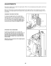
... Lat Bar. CHANGING THE WEIGHT SETTING To change the weight setting of the Weight Pin is used . 70 19 ATTACHING THE ACCESSORIES To attach the Lat Bar (63) to the Lat Cable (49), attach a Weight Clip (66) to see the correct form for each exercise. Note: The weight system works best when at least two Weights are properly tightened each time the weight system is touching the Weights, and turn the bent end upward. Refer to the accompanying exercise guide...
... Lat Bar. CHANGING THE WEIGHT SETTING To change the weight setting of the Weight Pin is used . 70 19 ATTACHING THE ACCESSORIES To attach the Lat Bar (63) to the Lat Cable (49), attach a Weight Clip (66) to see the correct form for each exercise. Note: The weight system works best when at least two Weights are properly tightened each time the weight system is touching the Weights, and turn the bent end upward. Refer to the accompanying exercise guide...

English Manual
Page 26
... use the press arms. ADJUSTING THE BACKREST The Backrest (31) can be adjusted to use the Curl Pad (33), remove the indicated 50mm Round Inner Cap (39) and insert the Curl Post (11) into the Front Leg (10). Tighten the Curl Adjustment Knob (58) into the Front Leg (10). Make sure the Adjustment Knob passes through a hole in the Guide Rods (18) and secure the Pin...
... use the press arms. ADJUSTING THE BACKREST The Backrest (31) can be adjusted to use the Curl Pad (33), remove the indicated 50mm Round Inner Cap (39) and insert the Curl Post (11) into the Front Leg (10). Tighten the Curl Adjustment Knob (58) into the Front Leg (10). Make sure the Adjustment Knob passes through a hole in the Guide Rods (18) and secure the Pin...

English Manual
Page 27
... 14 95 12 Hole WEIGHT RESISTANCE CHART The chart below shows the approximate weight resistance at each arm. Weight resistance shown for the butterfly arm station is for each station may vary due to either the position shown on the Front Leg (10), or the indicated hole in individual weight plates as well as friction between the cables, pulleys, and weight guides. equals .454 kg. 27...
... 14 95 12 Hole WEIGHT RESISTANCE CHART The chart below shows the approximate weight resistance at each arm. Weight resistance shown for the butterfly arm station is for each station may vary due to either the position shown on the Front Leg (10), or the indicated hole in individual weight plates as well as friction between the cables, pulleys, and weight guides. equals .454 kg. 27...

English Manual
Page 28
The numbers show the correct route for the cable. CABLE DIAGRAM The cable diagram shows the proper routing of the cables (49, 50, 51). Make sure that the cable and the cable traps have been assembled correctly. If the cable has not been correctly routed, the weight system will not function properly and damage may occur. Use the diagram to make sure that the cable traps do not touch or bind the cable. 2 5 1 4 Lat Cable (49) Length 147" / 373cm 3 1 3 Butterfly Cable (50) Length 114" / 289cm 4 2 Leg Lever Cable (51) Length 231" / 588cm 6 7 3 8 9 5 1 2 10 28
The numbers show the correct route for the cable. CABLE DIAGRAM The cable diagram shows the proper routing of the cables (49, 50, 51). Make sure that the cable and the cable traps have been assembled correctly. If the cable has not been correctly routed, the weight system will not function properly and damage may occur. Use the diagram to make sure that the cable traps do not touch or bind the cable. 2 5 1 4 Lat Cable (49) Length 147" / 373cm 3 1 3 Butterfly Cable (50) Length 114" / 289cm 4 2 Leg Lever Cable (51) Length 231" / 588cm 6 7 3 8 9 5 1 2 10 28
English Manual
Page 29
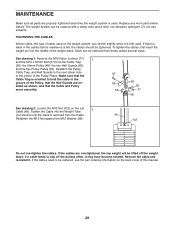
... cables before resistance is felt, the cables should be cleaned with a damp cloth and a mild, non-abrasive detergent. Remove the cable and re-install it may have become twisted. The weight system can be tightened. If the cables need to the center of the Pulley, that the Cable and Pulley move smoothly. 97 55 56 60 55 77 48 See drawing 2. MAINTENANCE Make sure all parts...
... cables before resistance is felt, the cables should be cleaned with a damp cloth and a mild, non-abrasive detergent. Remove the cable and re-install it may have become twisted. The weight system can be tightened. If the cables need to the center of the Pulley, that the Cable and Pulley move smoothly. 97 55 56 60 55 77 48 See drawing 2. MAINTENANCE Make sure all parts...
English Manual
Page 30
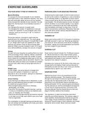
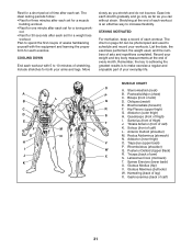
... can tone your body's signals. An example of the body. It is an individual matter. Exercising in any time while exercising, stop immediately and begin cooling down. The exertion stage of each exercise, and moving only the appropriate parts of a balanced program follows: • Plan strength training workouts on Tuesday and Thursday. • Rest from session to their capacity. A "set . Find out what...
... can tone your body's signals. An example of the body. It is an individual matter. Exercising in any time while exercising, stop immediately and begin cooling down. The exertion stage of each exercise, and moving only the appropriate parts of a balanced program follows: • Plan strength training workouts on Tuesday and Thursday. • Rest from session to their capacity. A "set . Find out what...
English Manual
Page 31
... workout with the equipment and learning the proper form for each exercise. Ease into each set for a toning work- Soleus (front of every month. Anterior Deltoid (shoulder) M. Triceps (back of arm) D. Latissimus Dorsi (mid back) T. Biceps (front of arm) S. Tibialis Anterior (front of calf) 31 Gluteus Medius (hip) V. Gastrocnemius (back of calf) K. List the date, the exercises performed, the weight used...
... workout with the equipment and learning the proper form for each exercise. Ease into each set for a toning work- Soleus (front of every month. Anterior Deltoid (shoulder) M. Triceps (back of arm) D. Latissimus Dorsi (mid back) T. Biceps (front of arm) S. Tibialis Anterior (front of calf) 31 Gluteus Medius (hip) V. Gastrocnemius (back of calf) K. List the date, the exercises performed, the weight used...
English Manual
Page 33
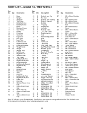
... Washer Screw 39 3 50mm Round Inner 81 2 M10 x 85mm Bolt 119 2 38mm Round Inner Cap 82 2 M10 x 75mm Bolt Cap 40 2 Press Arm Cap 83 5 M8 x 75mm Carriage # - Specifications are subject to change without notice. PART LIST-Model No. Description Key No. User's Manual 41 4 40mm x 20mm Inner Bolt # - Exercise Guide Cap 84 5 M10 x 80mm Bolt # - Grease Packet Cap 86 4 M10 x 45mm Bolt Note: "#" indicates a non-illustrated part. Qty. Description Key...
... Washer Screw 39 3 50mm Round Inner 81 2 M10 x 85mm Bolt 119 2 38mm Round Inner Cap 82 2 M10 x 75mm Bolt Cap 40 2 Press Arm Cap 83 5 M8 x 75mm Carriage # - Specifications are subject to change without notice. PART LIST-Model No. Description Key No. User's Manual 41 4 40mm x 20mm Inner Bolt # - Exercise Guide Cap 84 5 M10 x 80mm Bolt # - Grease Packet Cap 86 4 M10 x 45mm Bolt Note: "#" indicates a non-illustrated part. Qty. Description Key...
English Manual
Page 36
... to a product caused by ICON. ICON HEALTH & FITNESS, INC., 1500 S. 1000 W., LOGAN, UT 84321-9813 Part No. 250526 R0107A Printed in -home service, the customer will be the customer's responsibility. ICON's obligation under normal use and service conditions, for a minimal trip charge. Accordingly, the above limitation may also have other warranty beyond that specifically set forth above is limited to replacing or repairing, at ICON's option, the product...
... to a product caused by ICON. ICON HEALTH & FITNESS, INC., 1500 S. 1000 W., LOGAN, UT 84321-9813 Part No. 250526 R0107A Printed in -home service, the customer will be the customer's responsibility. ICON's obligation under normal use and service conditions, for a minimal trip charge. Accordingly, the above limitation may also have other warranty beyond that specifically set forth above is limited to replacing or repairing, at ICON's option, the product...


