
User Manual
Page 4
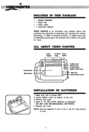
...UNDO button CLEAR button MARK LOCK button - dt VIDEO,.PAINTER INCLUDED IN THIS PACKAGE * 1 VIDEO PAINTER * 1 Video. A variety of the unit. 3. NOTE: Remove batteries if unit is turned OFF. 2. Pen * 1 Video cable * 1 Instruction Manual VIDEO PAINTER is an innovative new drawing device that combines ...the enjoyment of time. ALL ABOUT VIDEO PAINTER Drawing Pad Mark button Color Palette Function Power Keys Switch 40:4 0000 ...
...UNDO button CLEAR button MARK LOCK button - dt VIDEO,.PAINTER INCLUDED IN THIS PACKAGE * 1 VIDEO PAINTER * 1 Video. A variety of the unit. 3. NOTE: Remove batteries if unit is turned OFF. 2. Pen * 1 Video cable * 1 Instruction Manual VIDEO PAINTER is an innovative new drawing device that combines ...the enjoyment of time. ALL ABOUT VIDEO PAINTER Drawing Pad Mark button Color Palette Function Power Keys Switch 40:4 0000 ...
User Manual
Page 6
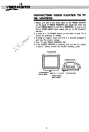
...should be switched to the RF Modulator section.) 2. If the VIDEO PAINTER is properly plugged in and has the correct voltage. 4. Attach one end of the video cable to the VIDEO OUTPUT on the TV or MONITOR. (If you are not ...VIDEO PAINTER and attach the other end to the VIDEO INPUT on the back of your TV, it is beeping, but you do not have a VIDEO INPUT Jack, please refer to VIDEO. 3. TV/MONITOR VIDEO PAINTER I DOCIO 000000 ♦ CIDO0 000000 TO THE VIDEO INPUT JACK VIDEO CABLE (INCLUDED) TO VIDEO OUT 3 Turn TV and VIDEO PAINTER ON. 5. VIDEOPAINTER CONNECTING VIDEO PAINTER...
...should be switched to the RF Modulator section.) 2. If the VIDEO PAINTER is properly plugged in and has the correct voltage. 4. Attach one end of the video cable to the VIDEO OUTPUT on the TV or MONITOR. (If you are not ...VIDEO PAINTER and attach the other end to the VIDEO INPUT on the back of your TV, it is beeping, but you do not have a VIDEO INPUT Jack, please refer to VIDEO. 3. TV/MONITOR VIDEO PAINTER I DOCIO 000000 ♦ CIDO0 000000 TO THE VIDEO INPUT JACK VIDEO CABLE (INCLUDED) TO VIDEO OUT 3 Turn TV and VIDEO PAINTER ON. 5. VIDEOPAINTER CONNECTING VIDEO PAINTER...
User Manual
Page 7
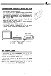
...and TV connected. 2. Hook up Video Cable from another system will need to the RF Modulator section.) 3. TV VCR CLECCD VIDEO PAINTER a 000 000poo OCICC2 000000 TO THE VIDEO INPUT JACK OF THE VCR VIDEO CABLE (INCLUDED) TO VIDEO OUT RF MODULATOR If your VCR does not have a VIDEO INPUT Jack, you are not getting...VCR. 4. If the VIDEO PAINTER is beeping, but you will not work. NOTE: A Game Switch from VIDEO PAINTER to VIDEO INPUT Jack on the front of the VCR. (If your TV does not have a VIDEO INPUT Jack please refer to purchase an RF Modulator, co-axial cable and 75/300 ohm...
...and TV connected. 2. Hook up Video Cable from another system will need to the RF Modulator section.) 3. TV VCR CLECCD VIDEO PAINTER a 000 000poo OCICC2 000000 TO THE VIDEO INPUT JACK OF THE VCR VIDEO CABLE (INCLUDED) TO VIDEO OUT RF MODULATOR If your VCR does not have a VIDEO INPUT Jack, you are not getting...VCR. 4. If the VIDEO PAINTER is beeping, but you will not work. NOTE: A Game Switch from VIDEO PAINTER to VIDEO INPUT Jack on the front of the VCR. (If your TV does not have a VIDEO INPUT Jack please refer to purchase an RF Modulator, co-axial cable and 75/300 ohm...
User Manual
Page 8
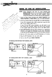
... jack, plug the other 11° end of the converter bVd -• to the coaxial cable and the other end to 75 ohms. 5. Hook the Coaxial Cable into the RF OUT on the TV and VIDEO PAINTER. Turn on the RF Modulator. RF MODULATOR WITHOUT VHF COAXIAL JACK RF Modulator (BACK VIEW... any wall outlet. 6. A If your area. Set the 1K/75 ohms switch on the RF Modulator. 2. Hook up Video Cable (included with VIDEO PAINTER) from • VIDEO PAINTER to VIDEO INPUT Jack on the RF Modulator to the VHF screws. 3. Remember to set both the RF Modulator and the TV to channel 3 or 4. ...
... jack, plug the other 11° end of the converter bVd -• to the coaxial cable and the other end to 75 ohms. 5. Hook the Coaxial Cable into the RF OUT on the TV and VIDEO PAINTER. Turn on the RF Modulator. RF MODULATOR WITHOUT VHF COAXIAL JACK RF Modulator (BACK VIEW... any wall outlet. 6. A If your area. Set the 1K/75 ohms switch on the RF Modulator. 2. Hook up Video Cable (included with VIDEO PAINTER) from • VIDEO PAINTER to VIDEO INPUT Jack on the RF Modulator to the VHF screws. 3. Remember to set both the RF Modulator and the TV to channel 3 or 4. ...
User Manual
Page 9
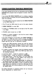
... Auxiliary Switch - should be switched to AUXILIARY c. d. Press PLAY until a picture appears on VCR. 6. The Video Cable is not "set" to accept the Video signal from the VIDEO PAINTER to LINE b. VIDEO PAINTER is working properly. Please read the sections that is necessary, on other VCR's a few choices will be handled... has the correct voltage (12 volt 800mA or 500mA.) If you have one of the above and VIDEO PAINTER is connected to accept Video In signal or Video Dubbing. 8. VIDEO PAINTER TROUBLE SHOOTING If you have followed all the hook up on the VCR, choose LINE. Locate your ...
... Auxiliary Switch - should be switched to AUXILIARY c. d. Press PLAY until a picture appears on VCR. 6. The Video Cable is not "set" to accept the Video signal from the VIDEO PAINTER to LINE b. VIDEO PAINTER is working properly. Please read the sections that is necessary, on other VCR's a few choices will be handled... has the correct voltage (12 volt 800mA or 500mA.) If you have one of the above and VIDEO PAINTER is connected to accept Video In signal or Video Dubbing. 8. VIDEO PAINTER TROUBLE SHOOTING If you have followed all the hook up on the VCR, choose LINE. Locate your ...

