VOT125 Datasheet
Page 1
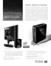
... display-mount options. Monitor sold separately. > Choose from these Intel® ULV (Ultra Low Voltage) Processors > - Intel® Core™ 2 Duo Processor SU7300 (VOT125-04) > Windows 7® Home Premium > VESA® mount kit (to attach to your desk and on the planet. Intel® Pentium® Processor SU4100 (VOT125-03) - Standard features include 2GB internal memory, 250GB hard drive, four USB 2.0 ports, DVI/HDMI outputs, and Ethernet/ wireless internet connections...
... display-mount options. Monitor sold separately. > Choose from these Intel® ULV (Ultra Low Voltage) Processors > - Intel® Core™ 2 Duo Processor SU7300 (VOT125-04) > Windows 7® Home Premium > VESA® mount kit (to attach to your desk and on the planet. Intel® Pentium® Processor SU4100 (VOT125-03) - Standard features include 2GB internal memory, 250GB hard drive, four USB 2.0 ports, DVI/HDMI outputs, and Ethernet/ wireless internet connections...

VOT125 Datasheet
Page 2
..., Dual Core (VOT125-04) Chipset Intel GS40 (VOT125-01/02/03) or GS45 (VOT125-04) MEMORY 2GB DDR2 SDRAM 800MHz SOFTWARE Operating System Windows® 7 Home Premium HARD DRIVE Capacity 250GB SATA 5400RPM COMMUNICATION Ethernet LAN 10/100/1000 Gigabit Ethernet Wireless LAN 802.11 b/g/n INPUT/OUTPUT USB 2.0 (x4) DVI out, HDMI out RJ45 Gigabit Ethernet LAN 3-in-1 card reader (SD, MMC, MS) Microphone jack Earphone jack POWER Power Adapter 19V DC; 65W adapter Power Cord 3-pin AC plug OPERATING...
..., Dual Core (VOT125-04) Chipset Intel GS40 (VOT125-01/02/03) or GS45 (VOT125-04) MEMORY 2GB DDR2 SDRAM 800MHz SOFTWARE Operating System Windows® 7 Home Premium HARD DRIVE Capacity 250GB SATA 5400RPM COMMUNICATION Ethernet LAN 10/100/1000 Gigabit Ethernet Wireless LAN 802.11 b/g/n INPUT/OUTPUT USB 2.0 (x4) DVI out, HDMI out RJ45 Gigabit Ethernet LAN 3-in-1 card reader (SD, MMC, MS) Microphone jack Earphone jack POWER Power Adapter 19V DC; 65W adapter Power Cord 3-pin AC plug OPERATING...
VOT125 User Guide (English)
Page 7
... tour 3 Getting Started 7 Setting up your PC 7 Mounting your PC to a monitor 10 Anti-theft protection with a Kensington Lock 11 Computer Stand 12 AMI BIOS Setup 13 Overview 13 Main Menu 14 Advanced Menu 15 Boot Menu 18 Chipset Menu 19 Power Menu 20 Security Menu 21 Exit Menu 21 System Recovery 23 When to Use System Recovery 23 Running Recovery Manager 23 FAQ & Troubleshooting 26 Frequently asked questions 26 Troubleshooting 27 ViewSonic VOT125
... tour 3 Getting Started 7 Setting up your PC 7 Mounting your PC to a monitor 10 Anti-theft protection with a Kensington Lock 11 Computer Stand 12 AMI BIOS Setup 13 Overview 13 Main Menu 14 Advanced Menu 15 Boot Menu 18 Chipset Menu 19 Power Menu 20 Security Menu 21 Exit Menu 21 System Recovery 23 When to Use System Recovery 23 Running Recovery Manager 23 FAQ & Troubleshooting 26 Frequently asked questions 26 Troubleshooting 27 ViewSonic VOT125
VOT125 User Guide (English)
Page 8
... Figure 1 Front Panel 3 Figure 2 Rear Panel 5 Figure 3 Connect the HDMI cable 7 Figure 4 Connect the DVI cable 8 Figure 5 Connecting USB mouse & keyboard 8 Figure 6 Network cable with RJ45 connector 9 Figure 7 Turing on the system 9 Figure 8 VESA mounting (1 10 Figure 9 VESA mounting (2 10 Figure 10 Use a Kensington lock 11 Figure 11 Computer Stand 12 Figure 12 Stand Dimension 12 Table 1 VOT125 product specifications 2 Table 2 BIOS Main Menu 14 Table 3 IDE Device Setting Menu 14 Table 4 System...
... Figure 1 Front Panel 3 Figure 2 Rear Panel 5 Figure 3 Connect the HDMI cable 7 Figure 4 Connect the DVI cable 8 Figure 5 Connecting USB mouse & keyboard 8 Figure 6 Network cable with RJ45 connector 9 Figure 7 Turing on the system 9 Figure 8 VESA mounting (1 10 Figure 9 VESA mounting (2 10 Figure 10 Use a Kensington lock 11 Figure 11 Computer Stand 12 Figure 12 Stand Dimension 12 Table 1 VOT125 product specifications 2 Table 2 BIOS Main Menu 14 Table 3 IDE Device Setting Menu 14 Table 4 System...
VOT125 User Guide (English)
Page 9
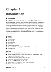
.... Its compact design and HDMI interface make it a perfect fit in -1 card reader and 4x USB „ 802.11 b/g/n Wireless Ethernet ViewSonic VOT125 1 Featuring the Intel® GMA graphics solution coupled with family and friends. Checklist „ VOT125 „ Power Adapter „ Power Cord „ Desktop Stand „ Driver CD „ Quick installation Guide „ Optional VESA Mounting Kit (with 4x M4X6 flat head screws) „ Recovery Disk Features „ Ultra...
.... Its compact design and HDMI interface make it a perfect fit in -1 card reader and 4x USB „ 802.11 b/g/n Wireless Ethernet ViewSonic VOT125 1 Featuring the Intel® GMA graphics solution coupled with family and friends. Checklist „ VOT125 „ Power Adapter „ Power Cord „ Desktop Stand „ Driver CD „ Quick installation Guide „ Optional VESA Mounting Kit (with 4x M4X6 flat head screws) „ Recovery Disk Features „ Ultra...
VOT125 User Guide (English)
Page 10
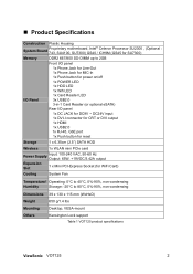
...) Rear I/O panel 1x DC JACK for DC9V ~ DC24V input 1x DVI-I connector for CRT or DVI output 1x HDMI 1x USB2.0 1x RJ-45, GbE port 1x Push button for reset Storage 1 x 6.35cm (2.5") SATA HDD Wireless 1x WLAN mini PCIe card Power Supply Input: 100-240 VAC, 50-60 Hz Output: 65W, +19VDC/3.42A output Expansion Slot 1 x Mini PCI-Express Socket (for WiFi Card) Cooling System Fan Temperature/ Operating...
...) Rear I/O panel 1x DC JACK for DC9V ~ DC24V input 1x DVI-I connector for CRT or DVI output 1x HDMI 1x USB2.0 1x RJ-45, GbE port 1x Push button for reset Storage 1 x 6.35cm (2.5") SATA HDD Wireless 1x WLAN mini PCIe card Power Supply Input: 100-240 VAC, 50-60 Hz Output: 65W, +19VDC/3.42A output Expansion Slot 1 x Mini PCI-Express Socket (for WiFi Card) Cooling System Fan Temperature/ Operating...

VOT125 User Guide (English)
Page 11
USB allows many devices to run simultaneously on a single computer, with USB devices such as additional plug-in sites or hubs. MIC-IN The microphone jack is compatible with some peripherals acting as keyboards, mouse devices, cameras, and hard disk drives. „ System tour Refer to the diagrams below to identify the components of the system. „ Front Panel Figure 1 Front Panel USB The USB (Universal Serial Bus) port is designed to connect the microphone used for video conferencing, voice narrations, or simple audio recordings. ViewSonic VOT125 3
USB allows many devices to run simultaneously on a single computer, with USB devices such as additional plug-in sites or hubs. MIC-IN The microphone jack is compatible with some peripherals acting as keyboards, mouse devices, cameras, and hard disk drives. „ System tour Refer to the diagrams below to identify the components of the system. „ Front Panel Figure 1 Front Panel USB The USB (Universal Serial Bus) port is designed to connect the microphone used for video conferencing, voice narrations, or simple audio recordings. ViewSonic VOT125 3
VOT125 User Guide (English)
Page 12
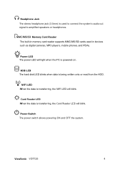
... transferring, the Card Reader LED will light when the PC is transferring, the WiFi LED will blink. ViewSonic VOT125 4 HDD LED The hard disk LED blinks when data is used in devices such as digital cameras, MP3 players, mobile phones, and PDAs. Memory Card Reader The built-in memory card reader supports MMC/MS/SD cards used to connect the system's audio out signal to amplified speakers or headphones. Power Switch The power switch allows powering ON and OFF the system. Power LED The power LED will blink. Headphone...
... transferring, the Card Reader LED will light when the PC is transferring, the WiFi LED will blink. ViewSonic VOT125 4 HDD LED The hard disk LED blinks when data is used in devices such as digital cameras, MP3 players, mobile phones, and PDAs. Memory Card Reader The built-in memory card reader supports MMC/MS/SD cards used to connect the system's audio out signal to amplified speakers or headphones. Power Switch The power switch allows powering ON and OFF the system. Power LED The power LED will blink. Headphone...
VOT125 User Guide (English)
Page 14
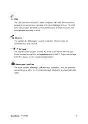
... as keyboards, mouse devices, cameras, and external storage devices. ViewSonic VOT125 6 To prevent damage to a local network. Ethernet The eight-pin RJ-45 LAN port supports a standard Ethernet cable for connection to the PC, always use with USB devices such as a hub. DC Jack The supplied power adapter converts AC power to run simultaneously on a single computer, with a key or combination lock attached to the PC. USB The USB (Universal Serial Bus) port is used for use the supplied power adapter. The USB ports allow multiple devices...
... as keyboards, mouse devices, cameras, and external storage devices. ViewSonic VOT125 6 To prevent damage to a local network. Ethernet The eight-pin RJ-45 LAN port supports a standard Ethernet cable for connection to the PC, always use with USB devices such as a hub. DC Jack The supplied power adapter converts AC power to run simultaneously on a single computer, with a key or combination lock attached to the PC. USB The USB (Universal Serial Bus) port is used for use the supplied power adapter. The USB ports allow multiple devices...
VOT125 User Guide (English)
Page 15
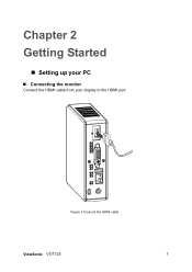
Figure 3 Connect the HDMI cable ViewSonic VOT125 7 Chapter 2 Getting Started „ Setting up your PC „ Connecting the monitor Connect the HDMI cable from your display to the HDMI port.
Figure 3 Connect the HDMI cable ViewSonic VOT125 7 Chapter 2 Getting Started „ Setting up your PC „ Connecting the monitor Connect the HDMI cable from your display to the HDMI port.
VOT125 User Guide (English)
Page 16
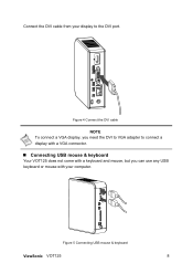
Connect the DVI cable from your computer. Figure 5 Connecting USB mouse & keyboard ViewSonic VOT125 8 Figure 4 Connect the DVI cable NOTE To connect a VGA display, you need the DVI to VGA adapter to connect a display with a VGA connector. „ Connecting USB mouse & keyboard Your VOT125 does not come with a keyboard and mouse, but you can use any USB keyboard or mouse with your display to the DVI port.
Connect the DVI cable from your computer. Figure 5 Connecting USB mouse & keyboard ViewSonic VOT125 8 Figure 4 Connect the DVI cable NOTE To connect a VGA display, you need the DVI to VGA adapter to connect a display with a VGA connector. „ Connecting USB mouse & keyboard Your VOT125 does not come with a keyboard and mouse, but you can use any USB keyboard or mouse with your display to the DVI port.
VOT125 User Guide (English)
Page 17
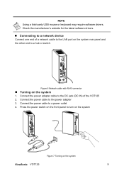
... a hub or switch. Connect the power cable to the DC jack (DC IN) of a network cable to the LAN port on the system rear panel and the other end to a power outlet 4. Connect the power adapter cable to the power adapter 3. Press the power switch on the front panel to turn on the system Figure 7 Turning on the system 1. NOTE Using a third-party USB mouse or keyboard may require software drivers. Figure 6 Network cable with RJ45 connector „ Turning on the system ViewSonic VOT125 9
... a hub or switch. Connect the power cable to the DC jack (DC IN) of a network cable to the LAN port on the system rear panel and the other end to a power outlet 4. Connect the power adapter cable to the power adapter 3. Press the power switch on the front panel to turn on the system Figure 7 Turning on the system 1. NOTE Using a third-party USB mouse or keyboard may require software drivers. Figure 6 Network cable with RJ45 connector „ Turning on the system ViewSonic VOT125 9
VOT125 User Guide (English)
Page 21
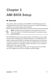
... specific information on the BIOS for your product, please contact ViewSonic AMI's ROM BIOS provides a built-in the CMOS only. It is a configuration change in this happens you will cause data loss in Setup program, which allows the user to be retained even when the power is added. NOTE: The BIOS menus and selections for your BIOS settings. The modified data will be stored in a battery...
... specific information on the BIOS for your product, please contact ViewSonic AMI's ROM BIOS provides a built-in the CMOS only. It is a configuration change in this happens you will cause data loss in Setup program, which allows the user to be retained even when the power is added. NOTE: The BIOS menus and selections for your BIOS settings. The modified data will be stored in a battery...

VOT125 User Guide (English)
Page 23
... Speed :800MHz V02.61 (C)Copyright 1985-2006, American Megatrends, Inc. „ Advanced Menu Table 5 Advanced Menu BIOS SETUP UTILITY Main Advanced Boot Chipset Power Security Advanced Settings WARNING: Setting wrong value in below sections may cause system to report server system information over a network. It allows AMIBIOS to use the SMART protocol to malfunction > CPU Configuration > OnBoard Peripherals Configuration > Hardware Health Configuration Select Screen ↑↓ Select Item +- Options: Auto, Disabled, Enabled...
... Speed :800MHz V02.61 (C)Copyright 1985-2006, American Megatrends, Inc. „ Advanced Menu Table 5 Advanced Menu BIOS SETUP UTILITY Main Advanced Boot Chipset Power Security Advanced Settings WARNING: Setting wrong value in below sections may cause system to report server system information over a network. It allows AMIBIOS to use the SMART protocol to malfunction > CPU Configuration > OnBoard Peripherals Configuration > Hardware Health Configuration Select Screen ↑↓ Select Item +- Options: Auto, Disabled, Enabled...
VOT125 User Guide (English)
Page 25
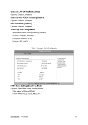
...Onboard Mini PCIE Controller [Enabled] Options: Enabled, Disabled HDA Controller [Enabled] Options: Enabled, Disabled > On-Chip ATA Configuration SATA Mode SelectConfiguration [Enabled] Options: Enabled, Disabled Configure SATA as [IDE] Options: IDE, AHCI Main Table 8 Hardware Health Configuration Advanced BIOS SETUP UTILITY Boot Chipset Power Security Exit Hardware Health Display CPU Shutdown Temperature FAN1 Mode Setting CPU Temperature Fan1 Speed :[Disabled] : [Smart Fan Mode] :41°C/105°F : 1621 RPM Select Screen ↑↓ Select Item +- Change Field Tab Select...
...Onboard Mini PCIE Controller [Enabled] Options: Enabled, Disabled HDA Controller [Enabled] Options: Enabled, Disabled > On-Chip ATA Configuration SATA Mode SelectConfiguration [Enabled] Options: Enabled, Disabled Configure SATA as [IDE] Options: IDE, AHCI Main Table 8 Hardware Health Configuration Advanced BIOS SETUP UTILITY Boot Chipset Power Security Exit Hardware Health Display CPU Shutdown Temperature FAN1 Mode Setting CPU Temperature Fan1 Speed :[Disabled] : [Smart Fan Mode] :41°C/105°F : 1621 RPM Select Screen ↑↓ Select Item +- Change Field Tab Select...

VOT125 User Guide (English)
Page 28
... [Disabled] Options: Disabled, Enabled ViewSonic VOT125 20 Suspend mode [S3 (STR)] Options: S1 (POS), S3 (STR) Repost Video on S3 Resume [No] Determines whether to invoke VGA BIOS post on AC Power Loss Resume From S3 By USB Device Resume By PCI-E Device Resume On RTC Alarm [S3 (STR)] [No] [Power Off] [Disabled] [Disabled] [Disabled] Select Screen ↑↓ Select Item +- „ Power Menu Main Advanced Table 11 Power Menu BIOS SETUP UTILITY Boot Chipset Power Security Exit Power Management Setting ACPI Function [Enabled...
... [Disabled] Options: Disabled, Enabled ViewSonic VOT125 20 Suspend mode [S3 (STR)] Options: S1 (POS), S3 (STR) Repost Video on S3 Resume [No] Determines whether to invoke VGA BIOS post on AC Power Loss Resume From S3 By USB Device Resume By PCI-E Device Resume On RTC Alarm [S3 (STR)] [No] [Power Off] [Disabled] [Disabled] [Disabled] Select Screen ↑↓ Select Item +- „ Power Menu Main Advanced Table 11 Power Menu BIOS SETUP UTILITY Boot Chipset Power Security Exit Power Management Setting ACPI Function [Enabled...
VOT125 User Guide (English)
Page 29
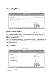
... 1985-2006, American Megatrends, Inc. Change Supervisor Password Select this operation. The Supervisor Password item on top of the screen displays the default Not Installed. Change User Password Select this item displays Installed. „ Security Menu Main Advanced Table 12 Security Menu BIOS SETUP UTILITY Boot Chipset Power Security Exit Security Setting Supervisor Password :Not Installed User Password :Not Installed Install or Change the password. Select Screen Change Supervisor Password Change User Password ↑↓ Select Item +- ViewSonic VOT125 21
... 1985-2006, American Megatrends, Inc. Change Supervisor Password Select this operation. The Supervisor Password item on top of the screen displays the default Not Installed. Change User Password Select this item displays Installed. „ Security Menu Main Advanced Table 12 Security Menu BIOS SETUP UTILITY Boot Chipset Power Security Exit Security Setting Supervisor Password :Not Installed User Password :Not Installed Install or Change the password. Select Screen Change Supervisor Password Change User Password ↑↓ Select Item +- ViewSonic VOT125 21
VOT125 User Guide (English)
Page 33
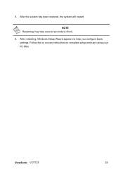
Follow the on screen instructions to help you configure basic settings. After the system has been restored, the system will restart. 5. After restarting, Windows Setup Wizard appears to complete setup and start using your PC Mini. NOTE Restarting may take several seconds to finish. 6. ViewSonic VOT125 25
Follow the on screen instructions to help you configure basic settings. After the system has been restored, the system will restart. 5. After restarting, Windows Setup Wizard appears to complete setup and start using your PC Mini. NOTE Restarting may take several seconds to finish. 6. ViewSonic VOT125 25

VOT125 User Guide (English)
Page 35
... connector Display (Using DVI-I to the display with the correct connector 2.3. If you do not see any image: 2.1. When system boots for more than 4 seconds you may have connected the VOT125 to D-Sub Adapter), Press "Ctrl+Alt+F4" for technical support. 4. „ Troubleshooting 1. No sound from headphones. „ Check the headphone cable connection - If the power LED stays lit and the system will not power down after holding the power button...
... connector Display (Using DVI-I to the display with the correct connector 2.3. If you do not see any image: 2.1. When system boots for more than 4 seconds you may have connected the VOT125 to D-Sub Adapter), Press "Ctrl+Alt+F4" for technical support. 4. „ Troubleshooting 1. No sound from headphones. „ Check the headphone cable connection - If the power LED stays lit and the system will not power down after holding the power button...
VOT125 User Guide (English)
Page 37
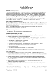
... or removed. 2. d. e. g. How to Customer Support page). For information about receiving service under warranty, contact ViewSonic Customer Support (Please refer to get service: 1. Removal or installation of nature, unauthorized product modification, or failure to follow instructions supplied with the product. For additional information or the name of the nearest ViewSonic service center, contact ViewSonic. 4.3: ViewSonic PC Mini Warranty Page 1 of the product. 3. The replacement unit will need to...
... or removed. 2. d. e. g. How to Customer Support page). For information about receiving service under warranty, contact ViewSonic Customer Support (Please refer to get service: 1. Removal or installation of nature, unauthorized product modification, or failure to follow instructions supplied with the product. For additional information or the name of the nearest ViewSonic service center, contact ViewSonic. 4.3: ViewSonic PC Mini Warranty Page 1 of the product. 3. The replacement unit will need to...


