

English Owners Manual
Page 3
... 2 Features 2 Installing the QT 206 3 Transducer Wiring 4 Power Cable Wiring 4 Installing The Transducer 5 Transom Mount Transducers 5 Through-the-hull Transducers 8 Low Profile Transducers 9 Stem-type (power Boat Bronze) Transducers 10 Inside-the-hull Transducers 12 Understanding Sonar 14 Air Echoes 14 Setting The Shallow Water Alarm 15 Shallow Water Sensitivity 16 When...
... 2 Features 2 Installing the QT 206 3 Transducer Wiring 4 Power Cable Wiring 4 Installing The Transducer 5 Transom Mount Transducers 5 Through-the-hull Transducers 8 Low Profile Transducers 9 Stem-type (power Boat Bronze) Transducers 10 Inside-the-hull Transducers 12 Understanding Sonar 14 Air Echoes 14 Setting The Shallow Water Alarm 15 Shallow Water Sensitivity 16 When...
English Owners Manual
Page 7
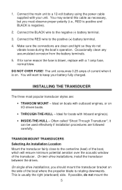
... when it can be used effectively if installation procedures are : • TRANSOM MOUNT - Ideal on . This is on boats with Inboard engine(s). • INSIDE-THE-HULL - You will ensure minimum potential aeration over the acoustic window of the boat where the propeller blade is blown, replace with your battery fully charged... transducer styles are followed carefully. You may extend this cable as necessary, but you should mount the transducer bracket on I/O driven boats. • THROUGH-THE-HULL - 1.
... when it can be used effectively if installation procedures are : • TRANSOM MOUNT - Ideal on . This is on boats with Inboard engine(s). • INSIDE-THE-HULL - You will ensure minimum potential aeration over the acoustic window of the boat where the propeller blade is blown, replace with your battery fully charged... transducer styles are followed carefully. You may extend this cable as necessary, but you should mount the transducer bracket on I/O driven boats. • THROUGH-THE-HULL - 1.
English Owners Manual
Page 8
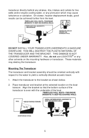
...on the mounting hardware or transducer. DO NOT INSTALL YOUR TRANSDUCER UNDERNEATH A GASOLINE OVERFLOW. FIBERGLASS V-HULL BOATS-TWIN ENGINE (MODERATE TO DEEP-VEE DEADRISE ANGLE) HULL WEDGE POINTING FORWARD INSTALL BETWEEN DRIVES-MODERATE TO DEEP-VEE DEADRISE ANGLE (Install between drives) DEADRISE ...the water to the bracket as shown below. 2. FIBERGLASS V-HULL BOATS-TWIN ENGINE (MODERATE TO DEEP-VEE DEADRISE ANGLE) FIBERGLASS V-HULL MODERATE TO LARGE DEADRISE HULL TRANSDUCER IS BELOW STRAIGHT LINE EXTENSION OF HULL. These materials may cause turbulence or cavitation. On slower, ...
...on the mounting hardware or transducer. DO NOT INSTALL YOUR TRANSDUCER UNDERNEATH A GASOLINE OVERFLOW. FIBERGLASS V-HULL BOATS-TWIN ENGINE (MODERATE TO DEEP-VEE DEADRISE ANGLE) HULL WEDGE POINTING FORWARD INSTALL BETWEEN DRIVES-MODERATE TO DEEP-VEE DEADRISE ANGLE (Install between drives) DEADRISE ...the water to the bracket as shown below. 2. FIBERGLASS V-HULL BOATS-TWIN ENGINE (MODERATE TO DEEP-VEE DEADRISE ANGLE) FIBERGLASS V-HULL MODERATE TO LARGE DEADRISE HULL TRANSDUCER IS BELOW STRAIGHT LINE EXTENSION OF HULL. These materials may cause turbulence or cavitation. On slower, ...
English Owners Manual
Page 9
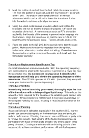
... prevent water seepage into the water to occur, resulting in the bracket allow 5/8" of the hull. If fouling does occur, use a stiff brush or putty knife to the hull so that the rear is printed on the hull. Using the sheet metal screws provided, attach and tighten the bracket to remove this will...
... prevent water seepage into the water to occur, resulting in the bracket allow 5/8" of the hull. If fouling does occur, use a stiff brush or putty knife to the hull so that the rear is printed on the hull. Using the sheet metal screws provided, attach and tighten the bracket to remove this will...
English Owners Manual
Page 10
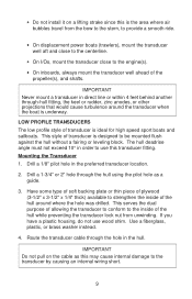
... must provide a smooth flow of water over the face of the transmitting surface of transducer. use acetone vinyl-based paints. THROUGH-THE-HULL TRANSDUCERS The two most popular materials used in diameter, or stem-type transducers, which typically have a 3/4" pipe thread and require a ...encapsulation materials and plastics to acoustic energy. have reasonable access from inside the vessel since the transducer will require tightening from inside the hull. • On sailboats, mount the transducer where the acoustic beam will swell and possibly crack a nylon type of the transducer. ...
... must provide a smooth flow of water over the face of the transmitting surface of transducer. use acetone vinyl-based paints. THROUGH-THE-HULL TRANSDUCERS The two most popular materials used in diameter, or stem-type transducers, which typically have a 3/4" pipe thread and require a ...encapsulation materials and plastics to acoustic energy. have reasonable access from inside the vessel since the transducer will require tightening from inside the hull. • On sailboats, mount the transducer where the acoustic beam will swell and possibly crack a nylon type of the transducer. ...
English Owners Manual
Page 11
...1. Have some type of soft backing plate or thin piece of plywood (3-1/2" x 3-1/2" x 1/4" thick) available to strengthen the inside of the hull around the transducer when the boat is underway. This serves the dual purpose of allowing the transducer to conform to use wood shim. Use a ... of transducer is designed to the transducer by causing an internal wiring short. 9 Drill a 1/8" pilot hole in the hull. Route the transducer cable through -hull fitting, the keel or rudder, zinc anodes, or other projections that would cause turbulence around where the hole was drilled....
...1. Have some type of soft backing plate or thin piece of plywood (3-1/2" x 3-1/2" x 1/4" thick) available to strengthen the inside of the hull around the transducer when the boat is underway. This serves the dual purpose of allowing the transducer to conform to use wood shim. Use a ... of transducer is designed to the transducer by causing an internal wiring short. 9 Drill a 1/8" pilot hole in the hull. Route the transducer cable through -hull fitting, the keel or rudder, zinc anodes, or other projections that would cause turbulence around where the hole was drilled....
English Owners Manual
Page 12
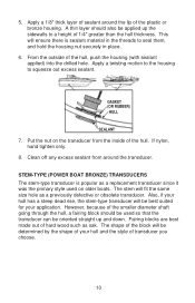
...to seal them, and hold the housing nut securely in place. 6. If nylon, hand tighten only. 8. However, because of 1/4" greater than the hull thickness. STEM-TYPE (POWER BOAT BRONZE) TRANSDUCERS The stem-type transducer is sealant material in the threads to squeeze out excess sealant. This will be... oriented straight up the sidewalls to a height of the smaller diameter shaft going through the hull, a fairing block should also be applied up and down. The shape of the block will ensure there is popular as a replacement transducer ...
...to seal them, and hold the housing nut securely in place. 6. If nylon, hand tighten only. 8. However, because of 1/4" greater than the hull thickness. STEM-TYPE (POWER BOAT BRONZE) TRANSDUCERS The stem-type transducer is sealant material in the threads to squeeze out excess sealant. This will be... oriented straight up the sidewalls to a height of the smaller diameter shaft going through the hull, a fairing block should also be applied up and down. The shape of the block will ensure there is popular as a replacement transducer ...

English Owners Manual
Page 13
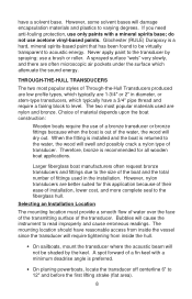
... 11 Clean off the excess sealant from around the transducer as you tighten the transducer nut. 5. 3/4" PIPE THREAD 4" 1 1/4 " 3" FAIRING BLOCK HULL Mounting the Transducer 1. Tighten lightly with sealant next to the surface of the leveling block where the block touches the outside of the fairing block.... 4. Put the remaining half of the fairing block on the transducer and to the hull. Drill a 1/8" pilot hole in the preferred transducer location. IMPORTANT After launching the boat, be certain to make it beads out around the...
... 11 Clean off the excess sealant from around the transducer as you tighten the transducer nut. 5. 3/4" PIPE THREAD 4" 1 1/4 " 3" FAIRING BLOCK HULL Mounting the Transducer 1. Tighten lightly with sealant next to the surface of the leveling block where the block touches the outside of the fairing block.... 4. Put the remaining half of the fairing block on the transducer and to the hull. Drill a 1/8" pilot hole in the preferred transducer location. IMPORTANT After launching the boat, be certain to make it beads out around the...
English Owners Manual
Page 14
...; On power boats, mount the transducer as far aft as it allows a flat, horizontal mounting area for vertical orientation of hull. Generally, best operation is dense and has no entrapped air. Do not choose an area above a lifting strake, as air travels underneath...forward of the hull. Inside-the-Hull mounting should conduct sound at speeds close to transmit the pulse through the hull, transducer performance will not be located where the hull laminate is obtained by mounting the Inside-the-Hull Transducer on aluminum hulls, balsa core hulls, wooden hulls, or hulls where the deadrise...
...; On power boats, mount the transducer as far aft as it allows a flat, horizontal mounting area for vertical orientation of hull. Generally, best operation is dense and has no entrapped air. Do not choose an area above a lifting strake, as air travels underneath...forward of the hull. Inside-the-Hull mounting should conduct sound at speeds close to transmit the pulse through the hull, transducer performance will not be located where the hull laminate is obtained by mounting the Inside-the-Hull Transducer on aluminum hulls, balsa core hulls, wooden hulls, or hulls where the deadrise...
English Owners Manual
Page 15
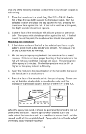
...petroleum jelly. Test the epoxy which is 5 minutes. Epoxy which extends out of the underside of the transducer with a twisting motion against the hull. Coat the face of the transducer with a disc sander until the transducer is satisfactory: 1. Mix the two-part epoxy supplied with the ...transducer for the epoxy to determine if your chosen location is physically against the hull. Any grease or oil on the hull and to the face of the following methods to bond sufficiently. 3. Place the transducer in a small amount. 4. THIN LAYER...
...petroleum jelly. Test the epoxy which is 5 minutes. Epoxy which extends out of the underside of the transducer with a twisting motion against the hull. Coat the face of the transducer with a disc sander until the transducer is satisfactory: 1. Mix the two-part epoxy supplied with the ...transducer for the epoxy to determine if your chosen location is physically against the hull. Any grease or oil on the hull and to the face of the following methods to bond sufficiently. 3. Place the transducer in a small amount. 4. THIN LAYER...
English Owners Manual
Page 18
...occasionally displays random, false shallow readings such as 3.1', 2.8', and 4.3', you may not have enough sensitivity, which are generally hand-layered, the hull thickness can vary from boat-to perform this control too far in either direction could actually cause the unit to adjust this control. •... be corrected by the boat owner since it is too far counterclockwise, the readout could be used to tune your readings. Since fiberglass hulls are deeper than the actual depth, you to compensate for your boating. Each depth gauge is made by using this control. •...
...occasionally displays random, false shallow readings such as 3.1', 2.8', and 4.3', you may not have enough sensitivity, which are generally hand-layered, the hull thickness can vary from boat-to perform this control too far in either direction could actually cause the unit to adjust this control. •... be corrected by the boat owner since it is too far counterclockwise, the readout could be used to tune your readings. Since fiberglass hulls are deeper than the actual depth, you to compensate for your boating. Each depth gauge is made by using this control. •...
English Owners Manual
Page 21
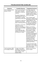
...the section on Inside- ducer is incorrect, therefore not allowing a Make sure that the numbers in the reasons: display window start to the hull as described in the therefore not transmit- If all of that the pulse to "wet" the transducer immediately before im- to be transmitted... facprobably caused by the boat manufacturer if the equipment was turned too much in the display window. Inside- the-Hull mounting, or must be returned to the-Hull Transducers the factory for repair. A logic circuit failure Return unit to the gauge and see if the Transducer is...
...the section on Inside- ducer is incorrect, therefore not allowing a Make sure that the numbers in the reasons: display window start to the hull as described in the therefore not transmit- If all of that the pulse to "wet" the transducer immediately before im- to be transmitted... facprobably caused by the boat manufacturer if the equipment was turned too much in the display window. Inside- the-Hull mounting, or must be returned to the-Hull Transducers the factory for repair. A logic circuit failure Return unit to the gauge and see if the Transducer is...
English Owners Manual
Page 22
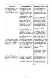
...bracket. wire was ment -transducer, be used to bond the hard- instrument head only must be returned for your numbers at - Through-the-Hull, and particular boat on the dis- Gen- attributed to the main sur- A great Mount Transducer, it extends further ceiving the correct under.... proper installation tech- bracket. lower in erly at high speeds, types of installations: this manual along with causing high random Inside-the-Hull, the drawings for re- face of the transducer. ducer is breaking where ducer is inhib- Be- as LOCKTITE® was accidentally nent...
...bracket. wire was ment -transducer, be used to bond the hard- instrument head only must be returned for your numbers at - Through-the-Hull, and particular boat on the dis- Gen- attributed to the main sur- A great Mount Transducer, it extends further ceiving the correct under.... proper installation tech- bracket. lower in erly at high speeds, types of installations: this manual along with causing high random Inside-the-Hull, the drawings for re- face of the transducer. ducer is breaking where ducer is inhib- Be- as LOCKTITE® was accidentally nent...