User Guide
Page 5
... service. Fax Branding The Telephone Consumer Protection Act of 1991 makes it unlawful for any person to use a computer or other electronic device, including Fax machines, to send any other entity, or individual. (The telephone number provided...number for which charges exceed local or long-distance transmission charges.) In order to program this information into your fax transmission, refer to the fax software instructions installed on this equipment causes harm to file a complaint with this equipment, for repair or warranty information, please contact Toshiba Corporation, Toshiba...
... service. Fax Branding The Telephone Consumer Protection Act of 1991 makes it unlawful for any person to use a computer or other electronic device, including Fax machines, to send any other entity, or individual. (The telephone number provided...number for which charges exceed local or long-distance transmission charges.) In order to program this information into your fax transmission, refer to the fax software instructions installed on this equipment causes harm to file a complaint with this equipment, for repair or warranty information, please contact Toshiba Corporation, Toshiba...

User Guide
Page 34
... from any location. You will find your operating system, Microsoft® Windows® XP Professional or Windows® 2000 (see Windows 2000 Supplemental Information), already installed on your work can accompany you wherever you to the world of the information provided herein, product specifications, configurations, prices, system/component/options availability are all subject to change without notice. With your Toshiba notebook computer, your...
... from any location. You will find your operating system, Microsoft® Windows® XP Professional or Windows® 2000 (see Windows 2000 Supplemental Information), already installed on your work can accompany you wherever you to the world of the information provided herein, product specifications, configurations, prices, system/component/options availability are all subject to change without notice. With your Toshiba notebook computer, your...

User Guide
Page 40
... "Using external display devices" on page 90. For more information, see "Using the i.LINK® port" on page 65. Ether Network port-Lets you connect a serial mouse, serial printer, or other parallel device. You can connect up to a conventional telephone line. 40 Finding Your Way Around Finding where everything is located Back RGB (monitor) port S-Video port Network port i Link port DC IN Serial port Parallel port Modem port Cooling vents _ + DC IN -Lets you connect an external monitor...
... "Using external display devices" on page 90. For more information, see "Using the i.LINK® port" on page 65. Ether Network port-Lets you connect a serial mouse, serial printer, or other parallel device. You can connect up to a conventional telephone line. 40 Finding Your Way Around Finding where everything is located Back RGB (monitor) port S-Video port Network port i Link port DC IN Serial port Parallel port Modem port Cooling vents _ + DC IN -Lets you connect an external monitor...

User Guide
Page 66
...: Toshiba recommends using a cable no longer than 20 feet (approximately 6 meters). If you 'll need to purchase an SVideo cable. 1 Connect one end of the S-Video cable to the external video device. 66 Connecting Other External Devices Using external display devices Connecting the display device If you 'll need to purchase an S-Video cable. To connect a device to the S-Video port, you 're connecting a television or other video display device to the computer's S-Video port, first refer to "Selecting video cables" below for the location of its S-Video...
...: Toshiba recommends using a cable no longer than 20 feet (approximately 6 meters). If you 'll need to purchase an SVideo cable. 1 Connect one end of the S-Video cable to the external video device. 66 Connecting Other External Devices Using external display devices Connecting the display device If you 'll need to purchase an S-Video cable. To connect a device to the S-Video port, you 're connecting a television or other video display device to the computer's S-Video port, first refer to "Selecting video cables" below for the location of its S-Video...

User Guide
Page 114
... "Connecting Other External Devices" on page 65. Make sure there is to purchase an optional PORT-Noteworthy® Computer Lock Cable. An external USB keyboard or a USB mouse connects to the serial port. PORT-Noteworthy® Computer Lock Cable To secure the computer: 1 Loop the cable through the loop. 3 Slide the PC Card lock (located underneath the PC Card slots) to a heavy object such as if it were a standard office computer. A serial mouse connects to the USB port. Using a computer lock For...
... "Connecting Other External Devices" on page 65. Make sure there is to purchase an optional PORT-Noteworthy® Computer Lock Cable. An external USB keyboard or a USB mouse connects to the serial port. PORT-Noteworthy® Computer Lock Cable To secure the computer: 1 Loop the cable through the loop. 3 Slide the PC Card lock (located underneath the PC Card slots) to a heavy object such as if it were a standard office computer. A serial mouse connects to the USB port. Using a computer lock For...

User Guide
Page 132
... when the battery alarm sounds Your Satellite computer can be configured to warn you of a low battery charge condition so you 're working in the Control Panel. button. 5 Select the Alarms tab and adjust the settings to suit your remaining charge frequently if you may take one . ❖ Install a secondary battery module in the computer's Slim SelectBay. The Windows operating system has additional power management options that can be accessed through an...
... when the battery alarm sounds Your Satellite computer can be configured to warn you of a low battery charge condition so you 're working in the Control Panel. button. 5 Select the Alarms tab and adjust the settings to suit your remaining charge frequently if you may take one . ❖ Install a secondary battery module in the computer's Slim SelectBay. The Windows operating system has additional power management options that can be accessed through an...
User Guide
Page 173
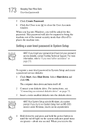
... light on the system indicator panel turns on /off . 2 Connect your password service diskette, contact Toshiba Technical Support. Setting a user-level password in System Setup HINT: If you try to "If you need further assistance" on page 72. 3 Insert a write-enabled diskette into Windows, you receive the HINT: Run System Setup outside Windows, at a system prompt. When you will also be asked for this password. For instructions, see "Connecting an external diskette drive...
... light on the system indicator panel turns on /off . 2 Connect your password service diskette, contact Toshiba Technical Support. Setting a user-level password in System Setup HINT: If you try to "If you need further assistance" on page 72. 3 Insert a write-enabled diskette into Windows, you receive the HINT: Run System Setup outside Windows, at a system prompt. When you will also be asked for this password. For instructions, see "Connecting an external diskette drive...
User Guide
Page 176
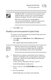
... . Select Shut down and turns itself off light on the system indicator panel turns on (green)-about one second. If you try , an "Incorrect Password" dialog box will need to turn off the computer, then reboot. 6 Click OK to enter a new password. HINT: Run System Setup outside Windows, at a system prompt. After three incorrect tries, this message appears: "Sorry, access denied! System Setup displays a setup screen. 3 Press P to move...
... . Select Shut down and turns itself off light on the system indicator panel turns on (green)-about one second. If you try , an "Incorrect Password" dialog box will need to turn off the computer, then reboot. 6 Click OK to enter a new password. HINT: Run System Setup outside Windows, at a system prompt. After three incorrect tries, this message appears: "Sorry, access denied! System Setup displays a setup screen. 3 Press P to move...

User Guide
Page 194
... "Installing a memory module" on page 79. 4 Reinstall the memory card following the instructions in the Conflicting device list. ❖ The Drivers tab, which lists the resources assigned to be device-related, so it 's seated properly. 5 Replace the memory expansion slot cover. 6 Check for these first. 1 Click Start, then click Shut Down. For further information about the device. ❖ The Resources tab, which displays the drivers being used by the device. 194 Troubleshooting Guide...
... "Installing a memory module" on page 79. 4 Reinstall the memory card following the instructions in the Conflicting device list. ❖ The Drivers tab, which lists the resources assigned to be device-related, so it 's seated properly. 5 Replace the memory expansion slot cover. 6 Check for these first. 1 Click Start, then click Shut Down. For further information about the device. ❖ The Resources tab, which displays the drivers being used by the device. 194 Troubleshooting Guide...

User Guide
Page 248
... hot key enables/disables the Dual Pointing Device. The wireless modes are: Bluetooth™ enabled-This enables the Bluetooth™ module (See "Using Bluetooth™" on page 99. Sample disable and enable Dual Pointing Device windows To use the TouchPad, see "Disabling or enabling the Dual Pointing Device" on page 154). Wireless device enable/disable Fn + This hot key enables the optional wireless devices installed in your computer. Wi-Fi enabled-This enables the Wi-Fi module. 248 Hot Keys Display brightness Display brightness Fn + This hot key decreases the screen...
... hot key enables/disables the Dual Pointing Device. The wireless modes are: Bluetooth™ enabled-This enables the Bluetooth™ module (See "Using Bluetooth™" on page 99. Sample disable and enable Dual Pointing Device windows To use the TouchPad, see "Disabling or enabling the Dual Pointing Device" on page 154). Wireless device enable/disable Fn + This hot key enables the optional wireless devices installed in your computer. Wi-Fi enabled-This enables the Wi-Fi module. 248 Hot Keys Display brightness Display brightness Fn + This hot key decreases the screen...

User Guide
Page 269
...-Memory cache installed on the screen that saves to the hard disk the current state of a computer system. K keyboard shortcut-A key or combination of using a pointing device such as the battery save mode. (2) A key or combination of keys that holds 1.44 MB of many Toshiba notebook computers that represents a function, file, or program. Internet-The decentralized, world-wide network of computers that you turn on the computer again, your work...
...-Memory cache installed on the screen that saves to the hard disk the current state of a computer system. K keyboard shortcut-A key or combination of using a pointing device such as the battery save mode. (2) A key or combination of keys that holds 1.44 MB of many Toshiba notebook computers that represents a function, file, or program. Internet-The decentralized, world-wide network of computers that you turn on the computer again, your work...

User Guide
Page 277
277 Index hot key 67 troubleshooting 198 display latch 39 display panel adjusting 43 closing 64 handling 43 opening 43 display settings 241 disposing of used batteries 137 DMA assignments 192 double-click 99 DVD player general problems 210 DVD-ROM drive 43 opening 109 troubleshooting 203 DVD-ROM or multi-function drive 147 playing audio CDs 147 E enabling Hibernation 234 Ethernet LAN port 152 expansion port 46 expansion capability 74 external diskette drive 72 display devices 40, 65 microphone 39 monitor 40, 67 video device 40...
277 Index hot key 67 troubleshooting 198 display latch 39 display panel adjusting 43 closing 64 handling 43 opening 43 display settings 241 disposing of used batteries 137 DMA assignments 192 double-click 99 DVD player general problems 210 DVD-ROM drive 43 opening 109 troubleshooting 203 DVD-ROM or multi-function drive 147 playing audio CDs 147 E enabling Hibernation 234 Ethernet LAN port 152 expansion port 46 expansion capability 74 external diskette drive 72 display devices 40, 65 microphone 39 monitor 40, 67 video device 40...
User Guide
Page 281
... Lock Cable 42 setting hard disk drive passwords 181 security lock slot 42 SelectServ 37 serial mouse 40 port 40 printer 40 setting up adding memory 75 computer 219, 220 computer's environment 50 PC Cards 86 software 219 setting up a connection 152 Setup Wizard 219 shortcuts 159 shut down 64 Shut down command 229, 231 Shut down methods 231 Shut down mode changing 239 hot key 239 Shutdown mode hot key 246 shutting down more quickly 118...
... Lock Cable 42 setting hard disk drive passwords 181 security lock slot 42 SelectServ 37 serial mouse 40 port 40 printer 40 setting up adding memory 75 computer 219, 220 computer's environment 50 PC Cards 86 software 219 setting up a connection 152 Setup Wizard 219 shortcuts 159 shut down 64 Shut down command 229, 231 Shut down methods 231 Shut down mode changing 239 hot key 239 Shutdown mode hot key 246 shutting down more quickly 118...
Maintenance Manual
Page 3
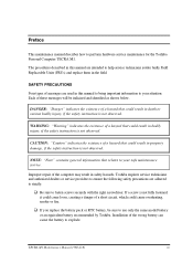
... following safety precautions are intended to use only the same model battery or an equivalent battery recommended by Toshiba. q If you replace the battery pack or RTC battery, be italicized and identified as shown below. DANGER: "Danger" indicates the existence of a hazard that relates to your safe maintenance service. q Be sure to perform hardware service maintenance for the Toshiba Personal Computer TECRA M1. Installation of the computer may result...
... following safety precautions are intended to use only the same model battery or an equivalent battery recommended by Toshiba. q If you replace the battery pack or RTC battery, be italicized and identified as shown below. DANGER: "Danger" indicates the existence of a hazard that relates to your safe maintenance service. q Be sure to perform hardware service maintenance for the Toshiba Personal Computer TECRA M1. Installation of the computer may result...
Maintenance Manual
Page 82
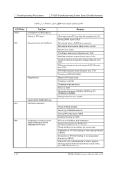
... (Check whether a refresh signal is working properly when refresh interval is out.) 2-22 TECRA M1 Maintenance Manual (960 -436) 2 Troubleshooting Procedures 2.5 FDD TroubleshootingSystem Board Troubleshooting Table 2-3 Printer port LED boot mode status (3/8) LED Status (02H) Test item Initialization of CMOS data (1) Setting of IRT status 03H Resume branch (at Cold Boot) Resume error System BIOS ROM/RAM copy 04H SM RAM initialization 05H Initialization of a device which needs initialization before initialization of PCI...
... (Check whether a refresh signal is working properly when refresh interval is out.) 2-22 TECRA M1 Maintenance Manual (960 -436) 2 Troubleshooting Procedures 2.5 FDD TroubleshootingSystem Board Troubleshooting Table 2-3 Printer port LED boot mode status (3/8) LED Status (02H) Test item Initialization of CMOS data (1) Setting of IRT status 03H Resume branch (at Cold Boot) Resume error System BIOS ROM/RAM copy 04H SM RAM initialization 05H Initialization of a device which needs initialization before initialization of PCI...

Maintenance Manual
Page 133
... Name ROM checksum Fan ON/OFF Gerserville Quick charge DMI read DMI write CPU Temperature Conventional memory Protected mode PS/2 Mouse connect check Touch Pad/IPS Stress Pressed key display Pressed key code display PS/2 Mouse connect check Touch Pad/IPS USB test InTouch/Presentation key VRAM read/write for VGA Gradation for VGA Gradation for LCD Gradation & Mode test for VGA All dot on / off for each test program in the DIAGNOSTIC TEST MENU...
... Name ROM checksum Fan ON/OFF Gerserville Quick charge DMI read DMI write CPU Temperature Conventional memory Protected mode PS/2 Mouse connect check Touch Pad/IPS Stress Pressed key display Pressed key code display PS/2 Mouse connect check Touch Pad/IPS USB test InTouch/Presentation key VRAM read/write for VGA Gradation for VGA Gradation for LCD Gradation & Mode test for VGA All dot on / off for each test program in the DIAGNOSTIC TEST MENU...
Maintenance Manual
Page 189
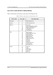
... name Data Compare Error ROM Checksum Error Parity Error Protected Mode Not Changed Memory Read/Write Error Cache Memory Error 2 Cache Error TAG-RAM Error Bad Command Address Mark Not Found Write Protected Record Not Found Media Removed DMA Overrun Error DMA Boundary Error CRC Error FDC Error Seek Error FDD Not Drive Error Time Out Error Write Buffer Error Time Out Fault Select Line Out Of Paper Power Off Busy Line 3-62 TECRA M1 Maintenance Manual (960 -436...
... name Data Compare Error ROM Checksum Error Parity Error Protected Mode Not Changed Memory Read/Write Error Cache Memory Error 2 Cache Error TAG-RAM Error Bad Command Address Mark Not Found Write Protected Record Not Found Media Removed DMA Overrun Error DMA Boundary Error CRC Error FDC Error Seek Error FDD Not Drive Error Time Out Error Write Buffer Error Time Out Fault Select Line Out Of Paper Power Off Busy Line 3-62 TECRA M1 Maintenance Manual (960 -436...

Maintenance Manual
Page 208
... BIOS version = X.XX PC CARD Controller Mode = Auto-Selected PERIPHERAL Internal Pointing Device Ext kayboard "Fn" Parallel Port Mode Hard Disk Mode =Enabled =Disabled =ECP =Enhanced LEGACY EMULATION USB KB/Mouse Legacy Emulation = Enabled USB-FDD Legacy Emulation = Enabled PCI LAN Built-in LAN = Enabled Select items Space, BkSp: Change values PgDn, PgUp: Change pages Esc: Exit without saving Home: Set default values End: Save changes and Exit 3-80 TECRA M1 Maintenance Manual (960-436) 3 Tests and Diagnostics 3.29 SETUP 3.29.2 Accessing...
... BIOS version = X.XX PC CARD Controller Mode = Auto-Selected PERIPHERAL Internal Pointing Device Ext kayboard "Fn" Parallel Port Mode Hard Disk Mode =Enabled =Disabled =ECP =Enhanced LEGACY EMULATION USB KB/Mouse Legacy Emulation = Enabled USB-FDD Legacy Emulation = Enabled PCI LAN Built-in LAN = Enabled Select items Space, BkSp: Change values PgDn, PgUp: Change pages Esc: Exit without saving Home: Set default values End: Save changes and Exit 3-80 TECRA M1 Maintenance Manual (960-436) 3 Tests and Diagnostics 3.29 SETUP 3.29.2 Accessing...

Maintenance Manual
Page 268
... 4.10 Memory Module 4.10 Memory Module Removing a Memory Module To remove a memory module, make sure the computer is in boot mode and powered off, follow the steps below and refer to remove a memory module with the computer turned on. CAUTION: 1) Do not try to figure 4-18. Turn up . 3. One end of the memory module will pop up the insulator covering the memory slots. 2. Press the two latches outward. Insulator Latches Memory slot A Memory slot B Memory module Figure 4-18 Removing the Memory module 4-36 TECRA M1 Maintenance Manual...
... 4.10 Memory Module 4.10 Memory Module Removing a Memory Module To remove a memory module, make sure the computer is in boot mode and powered off, follow the steps below and refer to remove a memory module with the computer turned on. CAUTION: 1) Do not try to figure 4-18. Turn up . 3. One end of the memory module will pop up the insulator covering the memory slots. 2. Press the two latches outward. Insulator Latches Memory slot A Memory slot B Memory module Figure 4-18 Removing the Memory module 4-36 TECRA M1 Maintenance Manual...

Memory Replacement Guide
Page 9
...; Portégé M200/M205 ■ Do not touch the connectors on the memory module or on the model of the computer. Contamination on the connectors may only show one memory module being replaced. User's Manual 3-1 Check your model and refer to remove the affected memory module(s) before installing the replacement(s). Be sure to the instructions for each affected module. 1. Remove or loosen the screws securing the memory module cover. 2. Removing the memory module cover 1. Memory Module Replacement Guide Chapter 3 Replacing...
...; Portégé M200/M205 ■ Do not touch the connectors on the memory module or on the model of the computer. Contamination on the connectors may only show one memory module being replaced. User's Manual 3-1 Check your model and refer to remove the affected memory module(s) before installing the replacement(s). Be sure to the instructions for each affected module. 1. Remove or loosen the screws securing the memory module cover. 2. Removing the memory module cover 1. Memory Module Replacement Guide Chapter 3 Replacing...


