User Guide
Page 5
... public utility commission, public service commission or corporation commission for repair or limited warranty information, please contact Toshiba Corporation, Toshiba America Information Systems, Inc. If Problems Arise If this , it may be required. If trouble is experienced with the FCC if you believe it unlawful for any person to use a computer or other entity, or individual. (The telephone number...
... public utility commission, public service commission or corporation commission for repair or limited warranty information, please contact Toshiba Corporation, Toshiba America Information Systems, Inc. If Problems Arise If this , it may be required. If trouble is experienced with the FCC if you believe it unlawful for any person to use a computer or other entity, or individual. (The telephone number...
User Guide
Page 56
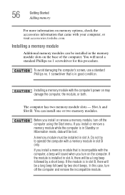
Installing a memory module Additional memory modules can install one or two memory modules. Installing a memory module with your computer, or visit accessories.toshiba.com. Do not try to operate the computer with the computer, a beep will sound when you install or remove a memory module, turn off the computer and remove the incompatible module. You can be installed in slot B only. Before you turn off the computer using the Start menu. A memory module must be a long beep followed by two short...
Installing a memory module Additional memory modules can install one or two memory modules. Installing a memory module with your computer, or visit accessories.toshiba.com. Do not try to operate the computer with the computer, a beep will sound when you install or remove a memory module, turn off the computer and remove the incompatible module. You can be installed in slot B only. Before you turn off the computer using the Start menu. A memory module must be a long beep followed by two short...
User Guide
Page 58
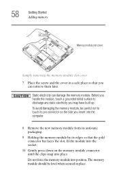
... Started Adding memory Memory module slot cover Sample removing the memory module slot cover 7 Place the screw and the cover in place. Do not force the memory module into place. The memory module should be careful not to discharge any static electricity you can damage the memory module. Before you handle the module, touch a grounded metal surface to touch its pin connector on the side you insert into the computer. 8 Remove the new memory module...
... Started Adding memory Memory module slot cover Sample removing the memory module slot cover 7 Place the screw and the cover in place. Do not force the memory module into place. The memory module should be careful not to discharge any static electricity you can damage the memory module. Before you handle the module, touch a grounded metal surface to touch its pin connector on the side you insert into the computer. 8 Remove the new memory module...
User Guide
Page 76
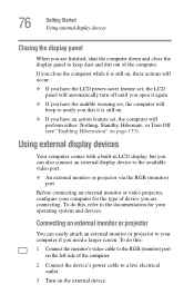
..., Standby, Hibernate, or Turn Off (see "Enabling Hibernation" on the external device. Before connecting an external monitor or video projector, configure your operating system and devices. 76 Getting Started Using external display devices Closing the display panel When you are connecting. Using external display devices Your computer comes with a built-in LCD display, but you need a larger screen. To do this : 1 Connect the monitor's video cable to the RGB (monitor) port on the left side of the computer. 2 Connect the device's power cable to a live electrical outlet...
..., Standby, Hibernate, or Turn Off (see "Enabling Hibernation" on the external device. Before connecting an external monitor or video projector, configure your operating system and devices. 76 Getting Started Using external display devices Closing the display panel When you are connecting. Using external display devices Your computer comes with a built-in LCD display, but you need a larger screen. To do this : 1 Connect the monitor's video cable to the RGB (monitor) port on the left side of the computer. 2 Connect the device's power cable to a live electrical outlet...

User Guide
Page 188
... problems, use the options in the Startup menu to start after the Starting Windows XP message appears. ❖ The operating system takes a long time to fix the problem. Data stored in Stand By mode and the battery has discharged. If pressing any key does not work routine, you change the system in some way such as installing a new program or adding a device. The computer was placed in the computer's memory...
... problems, use the options in the Startup menu to start after the Starting Windows XP message appears. ❖ The operating system takes a long time to fix the problem. Data stored in Stand By mode and the battery has discharged. If pressing any key does not work routine, you change the system in some way such as installing a new program or adding a device. The computer was placed in the computer's memory...

User Guide
Page 198
... cable connecting the external monitor to the computer is firmly attached. ❖ Try adjusting the contrast and brightness controls on the external monitor. ❖ Press Fn and F5 simultaneously to make sure the display priority is not set for the screen. To reduce the amount of flickering, try using the built-in screen, make sure the display priority is not set for the built-in screen flickers. To change the display settings...
... cable connecting the external monitor to the computer is firmly attached. ❖ Try adjusting the contrast and brightness controls on the external monitor. ❖ Press Fn and F5 simultaneously to make sure the display priority is not set for the screen. To reduce the amount of flickering, try using the built-in screen, make sure the display priority is not set for the built-in screen flickers. To change the display settings...
User Guide
Page 218
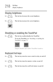
Fn + This hot key turns the numeric overlay on page 73. To use the TouchPad, see "Disabling or enabling the TouchPad" on and off. Fn + This hot key turns the scroll lock feature on and off . Disabling or enabling the TouchPad Fn + This hot key enables/disables the TouchPad. Fn + This hot key increases the screen brightness. Sample disable and enable TouchPad windows Keyboard hot keys Fn + This hot key turns the cursor control overlay on and off . 218 Hot Keys Display brightness Display brightness Fn + This hot key decreases the screen brightness.
Fn + This hot key turns the numeric overlay on page 73. To use the TouchPad, see "Disabling or enabling the TouchPad" on and off. Fn + This hot key turns the scroll lock feature on and off . Disabling or enabling the TouchPad Fn + This hot key enables/disables the TouchPad. Fn + This hot key increases the screen brightness. Sample disable and enable TouchPad windows Keyboard hot keys Fn + This hot key turns the cursor control overlay on and off . 218 Hot Keys Display brightness Display brightness Fn + This hot key decreases the screen brightness.
User Guide
Page 221
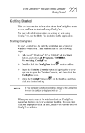
... connected to open the Toshiba Console, and then click the ConfigFree icon. ❖ Click the ConfigFree icon click the desired utility. 221 Using ConfigFree™ with an "X." You can then click the appropriate icon on setting up and using ConfigFree, see the Help File included in the application. For more detailed information on the Launcher to start and setup...
... connected to open the Toshiba Console, and then click the ConfigFree icon. ❖ Click the ConfigFree icon click the desired utility. 221 Using ConfigFree™ with an "X." You can then click the appropriate icon on setting up and using ConfigFree, see the Help File included in the application. For more detailed information on the Launcher to start and setup...
User Guide
Page 227
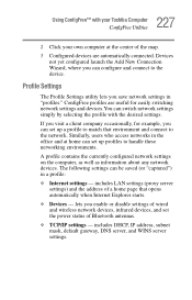
... set up profiles to the device. lets you enable or disable settings of wired and wireless network devices, infrared devices, and set the power status of the map. 3 Configured devices are useful for example, you save network settings in a profile: ❖ Internet settings - ConfigFree profiles are automatically connected. includes LAN settings (proxy server settings) and the address of a home page that environment and connect to match that opens automatically when Internet Explorer starts. ❖ Devices - Similarly, users who access networks...
... set up profiles to the device. lets you enable or disable settings of wired and wireless network devices, infrared devices, and set the power status of the map. 3 Configured devices are useful for example, you save network settings in a profile: ❖ Internet settings - ConfigFree profiles are automatically connected. includes LAN settings (proxy server settings) and the address of a home page that environment and connect to match that opens automatically when Internet Explorer starts. ❖ Devices - Similarly, users who access networks...
User Guide
Page 250
... setup 47 computer-friendly environment 41 computing tips 83 connecting to a power source 49 connection set up 144 control buttons 73 critical applications 3 Ctrl keys 86 D desktop creating new icon 139 major features 139 desktop exploration 138 desktop icons 139 Device Manager 193 checking properties 194 disabling a device 193, 194 devices keyboard 78 mouse 78 disable/enable TOSHIBA Touch and Launch 183 Disk Defragmenter 201 disk drive corrupted/damaged data files 201 missing files/trouble accessing a disk...
... setup 47 computer-friendly environment 41 computing tips 83 connecting to a power source 49 connection set up 144 control buttons 73 critical applications 3 Ctrl keys 86 D desktop creating new icon 139 major features 139 desktop exploration 138 desktop icons 139 Device Manager 193 checking properties 194 disabling a device 193, 194 devices keyboard 78 mouse 78 disable/enable TOSHIBA Touch and Launch 183 Disk Defragmenter 201 disk drive corrupted/damaged data files 201 missing files/trouble accessing a disk...
User Guide
Page 251
... display device external 76 display modes hot key 217 display output settings 77 display panel closing 76 display, external adjusting 78 disposal information 27 disposing of used batteries 127 DMA (Direct Memory Access) 192 double-click 73 DVD-ROM or multi-function drive cannot access disc 202 DVD-ROM/multi-function drive drive tray will not open 202 problems 202 troubleshooting 194 E energy saving features 114 ergonomics 44 error messages device driver conflict 191 general hardware problem 191 non-system disk or disk error 188, 202 problem with display settings/ current settings not working...
... display device external 76 display modes hot key 217 display output settings 77 display panel closing 76 display, external adjusting 78 disposal information 27 disposing of used batteries 127 DMA (Direct Memory Access) 192 double-click 73 DVD-ROM or multi-function drive cannot access disc 202 DVD-ROM/multi-function drive drive tray will not open 202 problems 202 troubleshooting 194 E energy saving features 114 ergonomics 44 error messages device driver conflict 191 general hardware problem 191 non-system disk or disk error 188, 202 problem with display settings/ current settings not working...
User Guide
Page 252
... mode 214 Stand By mode 215 volume mute 213 hot key power usage mode 129 hot key utility 168, 169 hot keys 213 hot swapping PC Cards 101 I icon 139 definition 39 desktop 139 hint 39 Internet Explorer 140 moving to desktop 139 recycle bin 140 safety 38 technical note 39 Industry Canada requirement 4 installation memory module 56 installing memory modules 55 mouse 78 instant passwords, using 175 Internal/External mode 199 Internet bookmarked site not found 190 connecting...
... mode 214 Stand By mode 215 volume mute 213 hot key power usage mode 129 hot key utility 168, 169 hot keys 213 hot swapping PC Cards 101 I icon 139 definition 39 desktop 139 hint 39 Internet Explorer 140 moving to desktop 139 recycle bin 140 safety 38 technical note 39 Industry Canada requirement 4 installation memory module 56 installing memory modules 55 mouse 78 instant passwords, using 175 Internal/External mode 199 Internet bookmarked site not found 190 connecting...
User Guide
Page 253
... upgrading 142 modules Wi-Fi Mini PC 136 monitor 76 connecting 76 not working 198 mouse installing 78 serial 78 using 132 N network 166 accessing 143 Dial-Up Networking Wizard 143 networking wireless 143 O office computing 131 opening the display panel 53 optional devices 131 other documentation 39 overlay keys 87 P password deleting a supervisor 177 disabling a user 176 supervisor set up 176 passwords instant, using 175 setting user 174 PC Card checklist 204 CIS (Card Information Structure) 204 configuring 158 errors 206 hot...
... upgrading 142 modules Wi-Fi Mini PC 136 monitor 76 connecting 76 not working 198 mouse installing 78 serial 78 using 132 N network 166 accessing 143 Dial-Up Networking Wizard 143 networking wireless 143 O office computing 131 opening the display panel 53 optional devices 131 other documentation 39 overlay keys 87 P password deleting a supervisor 177 disabling a user 176 supervisor set up 176 passwords instant, using 175 setting user 174 PC Card checklist 204 CIS (Card Information Structure) 204 configuring 158 errors 206 hot...
Maintenance Manual
Page 3
... safety instruction is a BTO-support personal computer. q If you replace the battery pack or RTC battery, be italicized and identified as shown below. The procedures described in safety hazards. Satellite A50/TECRA A 2 Maintenance Manual (960-478) iii Installation of the computer may result in this manual to bring important information to perform hardware service maintenance for the Toshiba Personal Computer Satellite A50/TECRA A2 series. NOTE: This Satellite A50/TECRA A2 series is...
... safety instruction is a BTO-support personal computer. q If you replace the battery pack or RTC battery, be italicized and identified as shown below. The procedures described in safety hazards. Satellite A50/TECRA A 2 Maintenance Manual (960-478) iii Installation of the computer may result in this manual to bring important information to perform hardware service maintenance for the Toshiba Personal Computer Satellite A50/TECRA A2 series. NOTE: This Satellite A50/TECRA A2 series is...
Maintenance Manual
Page 15
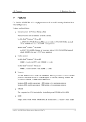
... (in 16-64MB. Memory modules can support 2GB in total as its maximum memory. Features are available in -one PC running a Pentium M or Celeron M processor. in 256MB, 512MB and 1,024MB sizes. Satellite A50/TECRA A 2 Maintenance Manual (960-478 ) 1-1 q HDD Single 20GB, 30GB, 40GB, 60GB or 80GB internal drive. 2.5 inch x 9.5mm height. 1.1 Features 1 Hardware Overview 1 Features 1.1 Features The Satellite A50/TECRA A2 is different from each model.
... (in 16-64MB. Memory modules can support 2GB in total as its maximum memory. Features are available in -one PC running a Pentium M or Celeron M processor. in 256MB, 512MB and 1,024MB sizes. Satellite A50/TECRA A 2 Maintenance Manual (960-478 ) 1-1 q HDD Single 20GB, 30GB, 40GB, 60GB or 80GB internal drive. 2.5 inch x 9.5mm height. 1.1 Features 1 Hardware Overview 1 Features 1.1 Features The Satellite A50/TECRA A2 is different from each model.

Maintenance Manual
Page 32
...-ROM: 105, DVD-ROM: 120, DVD-RAM: 130 (Typ.) CD-ROM: 105, DVD-ROM: 120, DVD-RAM: 130 (Typ.) CD-ROM: 105, DVD-ROM: 120, DVD-RAM: 130 (Typ.) 2,048KB CD-DA, CD+(E)G, CD-MIDI, CD-TEXT, CD-ROM, CDROM XA, CD -I, CD -I Bridge (Photo-CD, Video-CD), Multisession CD (Photo-CD, CD-EXTRA, CD-R, CD-RW, Portfolio), CD-R, CD-RW DVD-ROM (DVD-5, DVD-9, DVD-10, DVD-18), DVD-R (Ver.1.0, Ver.2.1) 1-18 Satellite A50/TECRA A2 Maintenance Manual...
...-ROM: 105, DVD-ROM: 120, DVD-RAM: 130 (Typ.) CD-ROM: 105, DVD-ROM: 120, DVD-RAM: 130 (Typ.) CD-ROM: 105, DVD-ROM: 120, DVD-RAM: 130 (Typ.) 2,048KB CD-DA, CD+(E)G, CD-MIDI, CD-TEXT, CD-ROM, CDROM XA, CD -I, CD -I Bridge (Photo-CD, Video-CD), Multisession CD (Photo-CD, CD-EXTRA, CD-R, CD-RW, Portfolio), CD-R, CD-RW DVD-ROM (DVD-5, DVD-9, DVD-10, DVD-18), DVD-R (Ver.1.0, Ver.2.1) 1-18 Satellite A50/TECRA A2 Maintenance Manual...
Maintenance Manual
Page 55
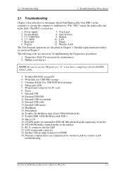
... Drive 9. Wireless LAN The Test Program operations are described in the field.) The FRUs covered are given in Chapter 4. Debug port LED 7. Microphone 16. LAN 11. RJ-11 connector checker LED 22. Keyboard 6. External USB FDD 11. Personal computer that can communicate by wireless LAN for PC card 8. Wraparound connector for wireless LAN troubleshooting Satellite A50/TECRA A2 Maintenance Manual (960-478) 2-1 External USB mouse 14. LAN wraparound connector 23. Toshiba CD-ROM test disk (ZA1217P01/P000204190) 17. 2.1 Troubleshooting 2 Troubleshooting Procedures...
... Drive 9. Wireless LAN The Test Program operations are described in the field.) The FRUs covered are given in Chapter 4. Debug port LED 7. Microphone 16. LAN 11. RJ-11 connector checker LED 22. Keyboard 6. External USB FDD 11. Personal computer that can communicate by wireless LAN for PC card 8. Wraparound connector for wireless LAN troubleshooting Satellite A50/TECRA A2 Maintenance Manual (960-478) 2-1 External USB mouse 14. LAN wraparound connector 23. Toshiba CD-ROM test disk (ZA1217P01/P000204190) 17. 2.1 Troubleshooting 2 Troubleshooting Procedures...

Maintenance Manual
Page 162
... out TX BUFFER FULL time out parity error framing error overrun error line status error modem status error Bad Command Error Address Mark Not Found Record Not Found HDC Not Reset Error Drive Not Initialize HDC overrun (DRQ) DMA Boundary Error Bad Sector Bad Track Error ECC Error ECC recover enable HDC Error Seek Error Time Out Error Drive Not Ready Undefined Error Write Fault Satellite A50/TECRA A2 Maintenance Manual (960 -478) 3-52
... out TX BUFFER FULL time out parity error framing error overrun error line status error modem status error Bad Command Error Address Mark Not Found Record Not Found HDC Not Reset Error Drive Not Initialize HDC overrun (DRQ) DMA Boundary Error Bad Sector Bad Track Error ECC Error ECC recover enable HDC Error Seek Error Time Out Error Drive Not Ready Undefined Error Write Fault Satellite A50/TECRA A2 Maintenance Manual (960 -478) 3-52
Maintenance Manual
Page 215
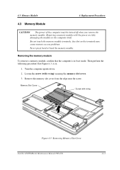
...remove the memory module. Removing the memory module To remove a memory module, confirm that the computer is in boot mode. Loosen the screw (with e-ring Figure 4-3 Removing Memory Slot Cover Satellite A50/TECRA A2 Maintenance Manual (960-478) 4-11 Memory Slot Cover Screw with e-ring) securing the memory slot cover. 3. Then perform the following procedure (See Figure 4-3, 4-4). 1. Turn the computer upside down. 2. Removing a memory module with the power on the terminals may cause memory access problems. Never press hard or bend the memory module. Do not touch the memory module...
...remove the memory module. Removing the memory module To remove a memory module, confirm that the computer is in boot mode. Loosen the screw (with e-ring Figure 4-3 Removing Memory Slot Cover Satellite A50/TECRA A2 Maintenance Manual (960-478) 4-11 Memory Slot Cover Screw with e-ring) securing the memory slot cover. 3. Then perform the following procedure (See Figure 4-3, 4-4). 1. Turn the computer upside down. 2. Removing a memory module with the power on the terminals may cause memory access problems. Never press hard or bend the memory module. Do not touch the memory module...
Maintenance Manual
Page 217
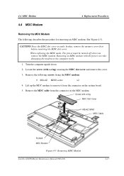
When replacing the MDC mode, The power must be turned off when you remove the MDC modem. Loosen the screw (with e-ring MDC Slot Cover M2x4Z BIND MDC Cable PJ3020 MDC Modem Figure 4-5 Removing MDC Modem Satellite A50/TECRA A2 Maintenance Manual (960-478) 4-13 Lift up the MDC modem to remove it from the connector on the MDC modem. Removing an MDC modem with the power on...
When replacing the MDC mode, The power must be turned off when you remove the MDC modem. Loosen the screw (with e-ring MDC Slot Cover M2x4Z BIND MDC Cable PJ3020 MDC Modem Figure 4-5 Removing MDC Modem Satellite A50/TECRA A2 Maintenance Manual (960-478) 4-13 Lift up the MDC modem to remove it from the connector on the MDC modem. Removing an MDC modem with the power on...


