
Replacement Instructions
Page 1
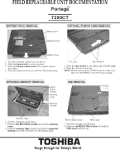
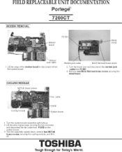
... eject buttonso the right to release the h.q. manager EXPANSION MEMORY REMOVAL black '17" omm HOD REMOVAL Memory clips TUI11 the computer upside down as shown. 2. FIELD REPLACEABLE UNIT DOCUMENTATION Portege" 7200CT BATTERY PACK REMOVAL Ba tery lock OPTIONAL PCMCIA CARD REMOVAL Release lever B tery Pack I Turn the computer upside down 2 RBMOVEI two WA hMuk screws securing the memory cover. cover 1 Turn the computer upside down 2 Remove one SUM black s crew securing the...
... eject buttonso the right to release the h.q. manager EXPANSION MEMORY REMOVAL black '17" omm HOD REMOVAL Memory clips TUI11 the computer upside down as shown. 2. FIELD REPLACEABLE UNIT DOCUMENTATION Portege" 7200CT BATTERY PACK REMOVAL Ba tery lock OPTIONAL PCMCIA CARD REMOVAL Release lever B tery Pack I Turn the computer upside down 2 RBMOVEI two WA hMuk screws securing the memory cover. cover 1 Turn the computer upside down 2 Remove one SUM black s crew securing the...
Replacement Instructions
Page 2
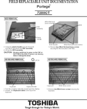
drive. holder at that, of the keyboard Keyboard 3 Remove two IQ. Remove four IL3x4 flat head brass screws secumg the HOD bracket to the HOD KEYBOARD REMOVAL Keyboard Keyboard holder 1 Turn the computer right side up and open.° display. 2 Unlatch the Keyha. KEYBOARD REMOVAL HOD et Iv13x4 flat heaa brass screws 5. FIELD REPLACEABLE UNIT DOCUMENTATION Portege" 7200CT HDD REMOVAL M3.4 (lal head boss.* HOD assembly HOD tic handle and...
drive. holder at that, of the keyboard Keyboard 3 Remove two IQ. Remove four IL3x4 flat head brass screws secumg the HOD bracket to the HOD KEYBOARD REMOVAL Keyboard Keyboard holder 1 Turn the computer right side up and open.° display. 2 Unlatch the Keyha. KEYBOARD REMOVAL HOD et Iv13x4 flat heaa brass screws 5. FIELD REPLACEABLE UNIT DOCUMENTATION Portege" 7200CT HDD REMOVAL M3.4 (lal head boss.* HOD assembly HOD tic handle and...
Replacement Instructions
Page 3
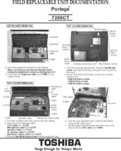
... Insulate. black screws -2 M2x14 black screws LCD cable nbr "ne FinLve, er PJ31 PJ770 PJ311 Mae braes PJ570 PJ741 Speaker cable Membrane switch cable S. meths lowers ver and Mrebra=li fraret lan KOZO 5 Remove two M2. Turn the computer right side up and open .° display. 4. Remove two M2.5. FIELD REPLACEABLE UNIT DOCUMENTATION Portege" 7200CT KEYBOARD REMOVAL TOP COVER REMOVAL Insulation MI6 blackw "IFT,P :tard 4 Lift out,M1e keyboard and set it...
... Insulate. black screws -2 M2x14 black screws LCD cable nbr "ne FinLve, er PJ31 PJ770 PJ311 Mae braes PJ570 PJ741 Speaker cable Membrane switch cable S. meths lowers ver and Mrebra=li fraret lan KOZO 5 Remove two M2. Turn the computer right side up and open .° display. 4. Remove two M2.5. FIELD REPLACEABLE UNIT DOCUMENTATION Portege" 7200CT KEYBOARD REMOVAL TOP COVER REMOVAL Insulation MI6 blackw "IFT,P :tard 4 Lift out,M1e keyboard and set it...

Replacement Instructions
Page 4
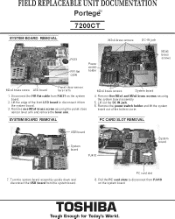
... the rnotlern jack cable and disconnect. brass screws securing the FIR board and lift it . switch COVer and remove the NembraneswItch FIR BOARD REMOVAL PJ1 FIR !la cable FIR boa C , IT' D:connect De RTC battery cable from RIM on the FIR board 2 Remove two IN2. je9r sard over and disconnect the FIR flat cable TOSHIBA Tough Enough for Today's World. FIELD REPLACEABLE UNIT DOCUMENTATION Portege" 7200CT SPEAKER REMOVAL MEMBRANE SWITCH REMOVAL aPv...
... the rnotlern jack cable and disconnect. brass screws securing the FIR board and lift it . switch COVer and remove the NembraneswItch FIR BOARD REMOVAL PJ1 FIR !la cable FIR boa C , IT' D:connect De RTC battery cable from RIM on the FIR board 2 Remove two IN2. je9r sard over and disconnect the FIR flat cable TOSHIBA Tough Enough for Today's World. FIELD REPLACEABLE UNIT DOCUMENTATION Portege" 7200CT SPEAKER REMOVAL MEMBRANE SWITCH REMOVAL aPv...
Replacement Instructions
Page 5
... PC card slot 8 Pull the PC card slots to disconnect from P.,110 on the system 2 .the edge OMB front LED board to disconnect it from N. lose sensor ler ,,L rrnect the Millie, cable from the system board. 3 Remove one IQ. on the system board TOSHIBA Tough Enough for Today's World. brass screw securing the panel close sensor lever arm a. FIELD REPLACEABLE UNIT DOCUMENTATION Portege" 7200CT SYSTEM BOARD REMOVAL...
... PC card slot 8 Pull the PC card slots to disconnect from P.,110 on the system 2 .the edge OMB front LED board to disconnect it from N. lose sensor ler ,,L rrnect the Millie, cable from the system board. 3 Remove one IQ. on the system board TOSHIBA Tough Enough for Today's World. brass screw securing the panel close sensor lever arm a. FIELD REPLACEABLE UNIT DOCUMENTATION Portege" 7200CT SYSTEM BOARD REMOVAL...
Replacement Instructions
Page 6
le and lift it from el shvesttrbOrar Modem jack cable 2 Tztna=r IA.3 flat head Nem screw and disconnect the modem jack 3 Remove one NI2r3 fiat head brass screw securing the metal brace COOLING MODULE Cooling Nodule Syetern board ,.em board assembly FI s.tle,uP... brass screws off four NI2.5. FIELD REPLACEABLE UNIT DOCUMENTATION Portege" 7200CT MODEM REMOVAL .rAt Modem bored Jae able 'dem board to disconnect it TOSHIBA Tough Enough for Today's World.
le and lift it from el shvesttrbOrar Modem jack cable 2 Tztna=r IA.3 flat head Nem screw and disconnect the modem jack 3 Remove one NI2r3 fiat head brass screw securing the metal brace COOLING MODULE Cooling Nodule Syetern board ,.em board assembly FI s.tle,uP... brass screws off four NI2.5. FIELD REPLACEABLE UNIT DOCUMENTATION Portege" 7200CT MODEM REMOVAL .rAt Modem bored Jae able 'dem board to disconnect it TOSHIBA Tough Enough for Today's World.
Replacement Instructions
Page 7
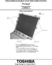
FIELD REPLACEABLE UNIT DOCUMENTATION Po rtege" 7200CT DISPLAY MASK REMOVAL Plastic seals f • Display mask ring the display e latches startIng TOSHIBA Tough Enough for Today's World.
FIELD REPLACEABLE UNIT DOCUMENTATION Po rtege" 7200CT DISPLAY MASK REMOVAL Plastic seals f • Display mask ring the display e latches startIng TOSHIBA Tough Enough for Today's World.
Replacement Instructions
Page 8
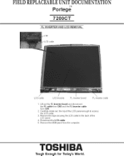
Carer* rotate out the top of the LCD panel enough to access the LCD cable 3 Remove the tape securing the LCD cable to the back of the LCD panel 4 Disconnect. LCD panel from the computer. TOSHIBA Tough Enough for Today's World. LCD cable 5 Remove*. FIELD REPLACEABLE UNIT DOCUMENTATION Po rtege" 7200CT FL INVERTER AND LCD REMOVAL LCD cable LCD cable LCD module FL inverter board FL inverter cable 1 Lift out the FL Inverter board and disconnect fromL cablefrom CN2 and the FL inverter cable cal 2.
Carer* rotate out the top of the LCD panel enough to access the LCD cable 3 Remove the tape securing the LCD cable to the back of the LCD panel 4 Disconnect. LCD panel from the computer. TOSHIBA Tough Enough for Today's World. LCD cable 5 Remove*. FIELD REPLACEABLE UNIT DOCUMENTATION Po rtege" 7200CT FL INVERTER AND LCD REMOVAL LCD cable LCD cable LCD module FL inverter board FL inverter cable 1 Lift out the FL Inverter board and disconnect fromL cablefrom CN2 and the FL inverter cable cal 2.


