Service Manual
Page 3
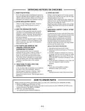
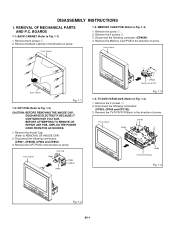
...keep the indications and notices in the original positions, or whether there are put these do not contact with the labels or seals on the TV. 3. MODEL NUMBER and VERSION LETTER The MODEL NUMBER can be more than 1M ohm, the inspection repair should be required. [Note 1] If... terminal HOW TO ORDER PARTS Please include the following informations when you order parts. (Particularly the VERSION LETTER.) 1. Remove the antenna terminal on TV and turn on the cabinet, chassis and parts. AVOID AN ELECTRIC SHOCK There is a high voltage part inside wiring is designed not to get...
...keep the indications and notices in the original positions, or whether there are put these do not contact with the labels or seals on the TV. 3. MODEL NUMBER and VERSION LETTER The MODEL NUMBER can be more than 1M ohm, the inspection repair should be required. [Note 1] If... terminal HOW TO ORDER PARTS Please include the following informations when you order parts. (Particularly the VERSION LETTER.) 1. Remove the antenna terminal on TV and turn on the cabinet, chassis and parts. AVOID AN ELECTRIC SHOCK There is a high voltage part inside wiring is designed not to get...

Service Manual
Page 8
... Cassette from the main unit as shown in the direction of the arrow by hand. (Refer to scratch the tape. Remove the Back Cabinet and TV/DVD/VCR Block. (Refer to wind the Video Tape in the direction of the DISASSEMBLY INSTRUCTIONS.) 2. TAPE REMOVAL METHOD AT NO POWER SUPPLY 1. Be... (Front Side) Fig. 2 DISC REMOVAL METHOD AT NO POWER SUPPLY 1. Rotate the Main Gear in the Cassette Case. 5. Manually open the Tray. Remove the TV/DVD/VCR block from the Deck Chassis. Repeat steps 3~4. Main Gear DVD Deck Fig. 1 A1-7 Rotate the Pinch Roller Cam in Fig. 1 below can be...
... Cassette from the main unit as shown in the direction of the arrow by hand. (Refer to scratch the tape. Remove the Back Cabinet and TV/DVD/VCR Block. (Refer to wind the Video Tape in the direction of the DISASSEMBLY INSTRUCTIONS.) 2. TAPE REMOVAL METHOD AT NO POWER SUPPLY 1. Be... (Front Side) Fig. 2 DISC REMOVAL METHOD AT NO POWER SUPPLY 1. Rotate the Main Gear in the Cassette Case. 5. Manually open the Tray. Remove the TV/DVD/VCR block from the Deck Chassis. Repeat steps 3~4. Main Gear DVD Deck Fig. 1 A1-7 Rotate the Pinch Roller Cam in Fig. 1 below can be...

Service Manual
Page 11
...CARD ...Y/C/AUDIO/HEAD AMP ...SERVO MICON ...REGULATOR ...IN/OUT ...SOUND AMP/SURROUND ...Hi-Fi/DEMODULATOR ...AV/SYNC COUNT/CONNECTOR ...TV ...TV MICON ...DVD IN/OUT ...INTERFACE ...MICON2 ...SCALER ...PRINTED CIRCUIT BOARDS DVD ...MAIN/CRT/OPERATION/CONNECTOR/VM COIL VCR ...HD-MI.../OUT ...SOUND AMP/SURROUND ...Hi-Fi ...TUNER/AV ...CHROMA/PROGRESSIVE/PIN CUSHION TV MICON ...SYNC COUNT/CONNECTOR ...ANALOG/DIGITAL CONVERTER ...SCALER ...DIGITAL COMB ...SDRAM ...IN/OUT/REGULATOR ...DEFLECTION ...TV POWER ...CRT/SVM ...POWER ...INTERFACE ...MICON2 ...LOADING MOTOR/SW ...INTERCONNECTION DIAGRAM1 ...
...CARD ...Y/C/AUDIO/HEAD AMP ...SERVO MICON ...REGULATOR ...IN/OUT ...SOUND AMP/SURROUND ...Hi-Fi/DEMODULATOR ...AV/SYNC COUNT/CONNECTOR ...TV ...TV MICON ...DVD IN/OUT ...INTERFACE ...MICON2 ...SCALER ...PRINTED CIRCUIT BOARDS DVD ...MAIN/CRT/OPERATION/CONNECTOR/VM COIL VCR ...HD-MI.../OUT ...SOUND AMP/SURROUND ...Hi-Fi ...TUNER/AV ...CHROMA/PROGRESSIVE/PIN CUSHION TV MICON ...SYNC COUNT/CONNECTOR ...ANALOG/DIGITAL CONVERTER ...SCALER ...DIGITAL COMB ...SDRAM ...IN/OUT/REGULATOR ...DEFLECTION ...TV POWER ...CRT/SVM ...POWER ...INTERFACE ...MICON2 ...LOADING MOTOR/SW ...INTERCONNECTION DIAGRAM1 ...
Service Manual
Page 12
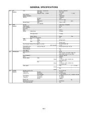
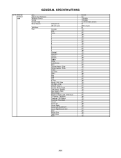
...System M 1 Tuner US (w/CABLE) 2~69, 4A,A-5~A-1, A~I, J~W,W+1~W+84 45.75MHz 41.25MHz 4.5MHz No US-Stereo Yes A3-1 Rev -- -- G-1 TV System G-2 VCR System G-3 DVD System G-4 Tuning System GENERAL SPECIFICATIONS CRT Color System Display Capability Speaker Sound Output System Video System Hi-Fi STEREO NTSC PB...Drive Search speed Fwd Actual Rev Actual Slow speed Actual Broadcasting System Tuner and Receive CH Intermediate Frequency Preset CH Stereo/Dual TV Sound Tuner Sound Muting System Destination CH Coverage Picture(FP) Sound(FS) FP-FS Actual 30 inch / 760mmV Flat ...
...System M 1 Tuner US (w/CABLE) 2~69, 4A,A-5~A-1, A~I, J~W,W+1~W+84 45.75MHz 41.25MHz 4.5MHz No US-Stereo Yes A3-1 Rev -- -- G-1 TV System G-2 VCR System G-3 DVD System G-4 Tuning System GENERAL SPECIFICATIONS CRT Color System Display Capability Speaker Sound Output System Video System Hi-Fi STEREO NTSC PB...Drive Search speed Fwd Actual Rev Actual Slow speed Actual Broadcasting System Tuner and Receive CH Intermediate Frequency Preset CH Stereo/Dual TV Sound Tuner Sound Muting System Destination CH Coverage Picture(FP) Sound(FS) FP-FS Actual 30 inch / 760mmV Flat ...

Service Manual
Page 14
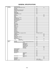
... Yes Bass Yes Treble Yes Balance Yes Stable Sound Yes Surround Yes HDMI Yes Reset Yes TV Setup Yes Language Yes Clock Set Yes Auto Clock Yes Standard Time Yes Daylight Saving Time Yes TV/CABLE Yes CH Program Yes ADD/Erase Yes Picture Size Yes Picture Scroll Yes Cinema Mode... Yes New Password Yes VCR Setup Yes Timer REC Set Yes Repeat Yes G-CODE(or SHOWVIEW or PLUSCODE)No. Entry Clock / Date No Yes TV/VCR Yes DVD Yes CH/AV(LINE) Yes Tape Counter(Linear Counter) Yes Tape Speed Yes Sleep Time Yes Stereo/Audio Output Yes Bilingual No...
... Yes Bass Yes Treble Yes Balance Yes Stable Sound Yes Surround Yes HDMI Yes Reset Yes TV Setup Yes Language Yes Clock Set Yes Auto Clock Yes Standard Time Yes Daylight Saving Time Yes TV/CABLE Yes CH Program Yes ADD/Erase Yes Picture Size Yes Picture Scroll Yes Cinema Mode... Yes New Password Yes VCR Setup Yes Timer REC Set Yes Repeat Yes G-CODE(or SHOWVIEW or PLUSCODE)No. Entry Clock / Date No Yes TV/VCR Yes DVD Yes CH/AV(LINE) Yes Tape Counter(Linear Counter) Yes Tape Speed Yes Sleep Time Yes Stereo/Audio Output Yes Bilingual No...
Service Manual
Page 15
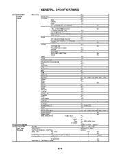
...and Timer Back-up GENERAL SPECIFICATIONS Menu (DVD) Menu Type Language Menu Subtitle Audio OSD Language(Set up Language) Video E.B.L. (Enhanced Black Level) TV Screen Size(4:3/16:9) OSD Display On/Off Picture Mode (Video/Film/Auto) JPEG Interval Audio DRC (Dynamic Range Control) Dialogue (On DRC...[TV] / Off DRC[Std]) Surround System Disc/Card Slot Password Lock/ Un Lock Parental Select Files HDMI (480p/1080i/720p) Output Open Close No...
...and Timer Back-up GENERAL SPECIFICATIONS Menu (DVD) Menu Type Language Menu Subtitle Audio OSD Language(Set up Language) Video E.B.L. (Enhanced Black Level) TV Screen Size(4:3/16:9) OSD Display On/Off Picture Mode (Video/Film/Auto) JPEG Interval Audio DRC (Dynamic Range Control) Dialogue (On DRC...[TV] / Off DRC[Std]) Surround System Disc/Card Slot Password Lock/ Un Lock Parental Select Files HDMI (480p/1080i/720p) Output Open Close No...
Service Manual
Page 16
...Menu Tracking- / Play Mode Cancel Cursor Up Cursor Down Cursor Left/Favorite CHCursor Right/Favorite CH+ Enter Picture Size Open/Close Eject RC-KH Yes TOSHIBA TOSHIBA 40-BFh,44-BBh,45-BAh 3V UM-4 x 2 pcs 50 Yes Yes Yes Yes Yes Yes Yes Yes Yes Yes Yes Yes Yes Yes...-5 G-14 Remote Control Unit GENERAL SPECIFICATIONS Unit Glow in Dark Remocon Remocon Format Format Custom Code Power Source Total Keys Keys Voltage(D.C) UM size x pcs TV/VCR DVD Power 1 2 3 4 5 6 7 8 9 0 ChannelChannel+ VolumeVolume+ Display Sleep Audio Select Mute Channel Return / SkipClosed Caption / Skip+ T-REC Rec/OTR Slow+ Play...
...Menu Tracking- / Play Mode Cancel Cursor Up Cursor Down Cursor Left/Favorite CHCursor Right/Favorite CH+ Enter Picture Size Open/Close Eject RC-KH Yes TOSHIBA TOSHIBA 40-BFh,44-BBh,45-BAh 3V UM-4 x 2 pcs 50 Yes Yes Yes Yes Yes Yes Yes Yes Yes Yes Yes Yes Yes Yes...-5 G-14 Remote Control Unit GENERAL SPECIFICATIONS Unit Glow in Dark Remocon Remocon Format Format Custom Code Power Source Total Keys Keys Voltage(D.C) UM size x pcs TV/VCR DVD Power 1 2 3 4 5 6 7 8 9 0 ChannelChannel+ VolumeVolume+ Display Sleep Audio Select Mute Channel Return / SkipClosed Caption / Skip+ T-REC Rec/OTR Slow+ Play...
Service Manual
Page 17
...Head Cleaning VIDEO PLUS+(SHOWVIEW,G-CODE) Auto Clock Auto Setup Forward / Reverse Picture Search CH Program (Auto CH Memory) Surround Stable Sound Closed Caption TV Auto Shut off Function End Call Index Search SQPB CABLE CM Skip(30sec x 6 Times) Comb Filter (3D) Mode (Picture Preference) Color ...ON/OFF Timer Favorite CH CH Label Video Label CH Lock Video Lock Game Timer Front Panel Lock Available Scan Rates (Component/HDMI) TV Monitor Program Extend Choke Coil Energy Star Protect of FBT Leak Circuit Zero Return Power On Memory V-chip USA V-chip CANADA V-chip ...
...Head Cleaning VIDEO PLUS+(SHOWVIEW,G-CODE) Auto Clock Auto Setup Forward / Reverse Picture Search CH Program (Auto CH Memory) Surround Stable Sound Closed Caption TV Auto Shut off Function End Call Index Search SQPB CABLE CM Skip(30sec x 6 Times) Comb Filter (3D) Mode (Picture Preference) Color ...ON/OFF Timer Favorite CH CH Label Video Label CH Lock Video Lock Game Timer Front Panel Lock Available Scan Rates (Component/HDMI) TV Monitor Program Extend Choke Coil Energy Star Protect of FBT Leak Circuit Zero Return Power On Memory V-chip USA V-chip CANADA V-chip ...

Service Manual
Page 18
.../OTR (VCR) Play (DVD) Stop (DVD) Skip+ /Search+ (DVD) Skip- /Search- (DVD) Open/Close (DVD) Input Select Main Power SW Indicator Power REC/OTR T-REC TV/VCR DVD Terminals Front Video Input Audio Input S Input 4 in 1 Card Slot Rear Compact Flash Card Slot Other Terminal Video Input Audio Input S Input Video...
.../OTR (VCR) Play (DVD) Stop (DVD) Skip+ /Search+ (DVD) Skip- /Search- (DVD) Open/Close (DVD) Input Select Main Power SW Indicator Power REC/OTR T-REC TV/VCR DVD Terminals Front Video Input Audio Input S Input 4 in 1 Card Slot Rear Compact Flash Card Slot Other Terminal Video Input Audio Input S Input Video...
Service Manual
Page 20
... POWER CORD FROM THE AC SOURCE. 1. Front Cabinet CRT PCB CP852 CP803 CP802B CP801 2 21 2 2 CP9604 Memory Card PCB Fig. 1-3 1-4: TV/DVD/VCR BLOCK (Refer to Fig. 1-2) CAUTION: BEFORE REMOVING THE ANODE CAP, DISCHARGE ELECTRICITY BECAUSE IT CONTAINS HIGH VOLTAGE. Remove the screw 1. 2.... Remove the 2 screws 1. 2. Front Cabinet CP1702 1 CP303 1 CP404 TV/DVD/VCR Block Fig. 1-4 Fig. 1-2 B1-1 Remove the Back Cabinet in the direction of arrow. Remove the CRT PCB in the direction of arrow...
... POWER CORD FROM THE AC SOURCE. 1. Front Cabinet CRT PCB CP852 CP803 CP802B CP801 2 21 2 2 CP9604 Memory Card PCB Fig. 1-3 1-4: TV/DVD/VCR BLOCK (Refer to Fig. 1-2) CAUTION: BEFORE REMOVING THE ANODE CAP, DISCHARGE ELECTRICITY BECAUSE IT CONTAINS HIGH VOLTAGE. Remove the screw 1. 2.... Remove the 2 screws 1. 2. Front Cabinet CP1702 1 CP303 1 CP404 TV/DVD/VCR Block Fig. 1-4 Fig. 1-2 B1-1 Remove the Back Cabinet in the direction of arrow. Remove the CRT PCB in the direction of arrow...

Service Manual
Page 21
... arrow. 1 Top Shield 1 1 1 1 1 1 1 1 1 1 Fig. 1-5 1-6: MAIN PCB (Refer to Fig. 1-5) 1. Disconnect the following connectors: (CP1701 and CP1707). 3. Disconnect the following connectors: (CP401). 4. CP1707 1 Power PCB CP1701 TV/DVD/VCR Block 1-7: TOP SHIELD (Refer to Fig. 1-8) 1. Remove the 4 screws 1. 2. Remove the 2 screws 2. 3. Remove the 2 screws 1. 2. Remove the Main PCB in the direction of...
... arrow. 1 Top Shield 1 1 1 1 1 1 1 1 1 1 Fig. 1-5 1-6: MAIN PCB (Refer to Fig. 1-5) 1. Disconnect the following connectors: (CP1701 and CP1707). 3. Disconnect the following connectors: (CP401). 4. CP1707 1 Power PCB CP1701 TV/DVD/VCR Block 1-7: TOP SHIELD (Refer to Fig. 1-8) 1. Remove the 4 screws 1. 2. Remove the 2 screws 2. 3. Remove the 2 screws 1. 2. Remove the Main PCB in the direction of...
Service Manual
Page 39
... the Tracking to the "ELECTRICAL ADJUSTMENT" (PG SHIFTER). 2 Adjusting of DVD disc at DVD mode. Set Condition Set Key Remocon Standard Key Time Operations TV mode VOL. (-) MIN 0 TV mode VOL. (-) MIN 1 VCR mode (Playback) VOL. (-) MIN 2 VCR mode VOL. (-) MIN (Playback) 3 VCR mode (Playback) VOL. (-) MIN 4 ... DVD mode (No disc) REC/OTR 4 2 Can be checked of the INITIAL DATA of MEMORY IC. Initialization of MEMORY IC. RATING LEVEL". TV mode VOL. (-) MIN 6 2 Can be checked of the INITIAL DATA of factory on the screen when the Tray Lock is provided with the ...
... the Tracking to the "ELECTRICAL ADJUSTMENT" (PG SHIFTER). 2 Adjusting of DVD disc at DVD mode. Set Condition Set Key Remocon Standard Key Time Operations TV mode VOL. (-) MIN 0 TV mode VOL. (-) MIN 1 VCR mode (Playback) VOL. (-) MIN 2 VCR mode VOL. (-) MIN (Playback) 3 VCR mode (Playback) VOL. (-) MIN 4 ... DVD mode (No disc) REC/OTR 4 2 Can be checked of the INITIAL DATA of MEMORY IC. Initialization of MEMORY IC. RATING LEVEL". TV mode VOL. (-) MIN 6 2 Can be checked of the INITIAL DATA of factory on the screen when the Tray Lock is provided with the ...

Service Manual
Page 40
... the rubber, and parts which the rubber touches. Clean the Head : Clean : Check it and if necessary, replace it. NOTE: If you set to the TV mode. 2. DOWN button on the set and Channel button (6) on the POWER, and set a factory initialization, the total hours is reset to minimum. 3. PREVENTIVE CHECKS...
... the rubber, and parts which the rubber touches. Clean the Head : Clean : Check it and if necessary, replace it. NOTE: If you set to the TV mode. 2. DOWN button on the set and Channel button (6) on the POWER, and set a factory initialization, the total hours is reset to minimum. 3. PREVENTIVE CHECKS...

Service Manual
Page 42
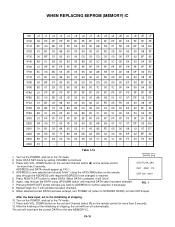
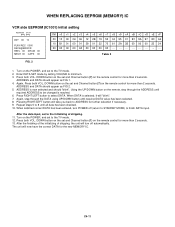
... has been required to change the MEMORY IC, the following steps should be taken to ensure correct data settings while making reference to TABLE 1 and 2. TV side EEPROM (IC101) initial setting INI +0 +1 +2 +3 +4 +5 +6 +7 +8 +9 +A +B +C +D +E +F 0000 FF 72 3D 01 A2 1F 97 FF 4A E4 B3 03 0D 36 03 64 0010 01...
... has been required to change the MEMORY IC, the following steps should be taken to ensure correct data settings while making reference to TABLE 1 and 2. TV side EEPROM (IC101) initial setting INI +0 +1 +2 +3 +4 +5 +6 +7 +8 +9 +A +B +C +D +E +F 0000 FF 72 3D 01 A2 1F 97 FF 4A E4 B3 03 0D 36 03 64 0010 01...
Service Manual
Page 51
... 2 seconds. 12. Press both VOL. After the finishing of the initializing of shipping. 10. The unit will take you back to the TV mode. 11. C4-10 Enter DATA SET mode by setting VOLUME to select DATA. Pressing RIGHT/LEFT button will now have the correct DATA ... been entered, turn off (return to STANDBY MODE) to the initializing of shipping, the unit will "blink". 6. Turn on the POWER, and set to the TV mode. 2. ADDRESS and DATA should "blink". FIG. 1 8. ADDRESS is reached. Press RIGHT/LEFT button to minimum. 3. Again, step through the ADDRESS until...
... 2 seconds. 12. Press both VOL. After the finishing of the initializing of shipping. 10. The unit will take you back to the TV mode. 11. C4-10 Enter DATA SET mode by setting VOLUME to select DATA. Pressing RIGHT/LEFT button will now have the correct DATA ... been entered, turn off (return to STANDBY MODE) to the initializing of shipping, the unit will "blink". 6. Turn on the POWER, and set to the TV mode. 2. ADDRESS and DATA should "blink". FIG. 1 8. ADDRESS is reached. Press RIGHT/LEFT button to minimum. 3. Again, step through the ADDRESS until...
Service Manual
Page 52
... will "blink". 7. When DATA is now selected and should appear as FIG 1. 4. Repeat steps 5 to finish DATA input. Press RIGHT/LEFT button to the TV mode. 12. Press both VOL. Turn on the POWER, and set and Channel button (7) on the remote control for more than 2 seconds. 13. DOWN button..., step through the DATA using UP/DOWN button until all data has been checked. 10. Using the UP/DOWN button on the set to the TV mode. 2. ADDRESS is selected, it will now have the correct DATA for more than 2 seconds. After the finishing of the initializing of shipping. 11....
... will "blink". 7. When DATA is now selected and should appear as FIG 1. 4. Repeat steps 5 to finish DATA input. Press RIGHT/LEFT button to the TV mode. 12. Press both VOL. Turn on the POWER, and set and Channel button (7) on the remote control for more than 2 seconds. 13. DOWN button..., step through the DATA using UP/DOWN button until all data has been checked. 10. Using the UP/DOWN button on the set to the TV mode. 2. ADDRESS is selected, it will now have the correct DATA for more than 2 seconds. After the finishing of the initializing of shipping. 11....

Service Manual
Page 53
... Playback PREPARATION FOR SERVICING How to insert or eject a cassette tape. Turn on a paper so that they have no short-circuit each other. 2. Remove the TV/DVD/VCR Block from the set. No.
... Playback PREPARATION FOR SERVICING How to insert or eject a cassette tape. Turn on a paper so that they have no short-circuit each other. 2. Remove the TV/DVD/VCR Block from the set. No.
Service Manual
Page 58
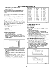
...POSI 03 V.POSI 04 H. Multi-sound Generator 4. Playback the alignment tape. 3. When the REC indicator is completed. (If the above adjustments doesn't work well:) TV FULL 00 OSD H 1 Fig. 1-1 5. Press the MENU button on the remote control for more than 2 seconds to select the options shown in its original... position. • When you exchange IC and Transistor for AV, CS and HD-MI mode, press the TV/VIDEO button on the remote control to set and the channel button (3) on the screen as shown in Fig. 1-1. (VCR SECTION) 2-1: PG SHIFTER...
...POSI 03 V.POSI 04 H. Multi-sound Generator 4. Playback the alignment tape. 3. When the REC indicator is completed. (If the above adjustments doesn't work well:) TV FULL 00 OSD H 1 Fig. 1-1 5. Press the MENU button on the remote control for more than 2 seconds to select the options shown in its original... position. • When you exchange IC and Transistor for AV, CS and HD-MI mode, press the TV/VIDEO button on the remote control to set and the channel button (3) on the screen as shown in Fig. 1-1. (VCR SECTION) 2-1: PG SHIFTER...
Service Manual
Page 59
... clockwise once. (Refer to select 1080i. 5. Receive the gray scale pattern from the Pattern Generator. 3. Receive the monoscope pattern. 9. Focus VR F1 VR F2 VR TV FULL 00 OSD H 1 A B Fig. 2-3 2-6: HORIZONTAL POSITION/ HORIZONTAL SIZE 1. And, then press the LEFT/ RIGHT button on the remote control to Fig. 2-3) NOTE: Adjust after performing...
... clockwise once. (Refer to select 1080i. 5. Receive the gray scale pattern from the Pattern Generator. 3. Receive the monoscope pattern. 9. Focus VR F1 VR F2 VR TV FULL 00 OSD H 1 A B Fig. 2-3 2-6: HORIZONTAL POSITION/ HORIZONTAL SIZE 1. And, then press the LEFT/ RIGHT button on the remote control to Fig. 2-3) NOTE: Adjust after performing...
Service Manual
Page 60
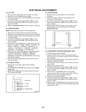
...screen mode to select 1080i. 5. Press the VOL. Receive the monoscope pattern. 9. Set the screen mode to the CS mode. 10. Press the TV/VIDEO button on the remote control to set to the CS mode.Then perform the above adjustments 2~5. 2-10: SUB CONTRAST 1. Check if the step ... adjustment mode display of Fig. 1-1 and press the channel button (05) on the remote control until the white 2.7% is normal. 5. Press the TV/VIDEO button on the remote control to the AV mode. SUB CONT is normal. Press the MENU button. Receive the monoscope pattern. (Audio Video Input...
...screen mode to select 1080i. 5. Press the VOL. Receive the monoscope pattern. 9. Set the screen mode to the CS mode. 10. Press the TV/VIDEO button on the remote control to set to the CS mode.Then perform the above adjustments 2~5. 2-10: SUB CONTRAST 1. Check if the step ... adjustment mode display of Fig. 1-1 and press the channel button (05) on the remote control until the white 2.7% is normal. 5. Press the TV/VIDEO button on the remote control to the AV mode. SUB CONT is normal. Press the MENU button. Receive the monoscope pattern. (Audio Video Input...


