Installation Instructions
Page 2
...Before You Begin 3 General Information 4 Installation Preparation 6 Ductwork Preparation 7 Electrical Requirements 10 Choosing the Correct Blower 10 Installation Instructions 11 Blower Motor Installation 11 Remote Installation (optional 15 VCIN Model Installation 18 VCIB Model Installation 26 Installing Filters, Filter Spacers, & Grease Trays 28 Service 29 Before Calling Service 29 Product Data Rating Plate 29 Installer Checklist 29 To Clean & Protect Exterior Surfaces 30 THERMADOR® Service, Parts & Accessories back page This THERMADOR® appliance is made by BSH Home...
...Before You Begin 3 General Information 4 Installation Preparation 6 Ductwork Preparation 7 Electrical Requirements 10 Choosing the Correct Blower 10 Installation Instructions 11 Blower Motor Installation 11 Remote Installation (optional 15 VCIN Model Installation 18 VCIB Model Installation 26 Installing Filters, Filter Spacers, & Grease Trays 28 Service 29 Before Calling Service 29 Product Data Rating Plate 29 Installer Checklist 29 To Clean & Protect Exterior Surfaces 30 THERMADOR® Service, Parts & Accessories back page This THERMADOR® appliance is made by BSH Home...
Installation Instructions
Page 3
... number listed on accidentally. Requirement: 120 VAC, 60 Hz 15 A. Allow the appliance to prevent power from being switched on the back page. • Before servicing or cleaning unit, switch power off before wiring this manual for guidance. If you have a qualified electrician install an outlet near the appliance. INSTALLER: Please leave these Instructions for easy reference. Show the owner the location of the appliance unless specifically...
... number listed on accidentally. Requirement: 120 VAC, 60 Hz 15 A. Allow the appliance to prevent power from being switched on the back page. • Before servicing or cleaning unit, switch power off before wiring this manual for guidance. If you have a qualified electrician install an outlet near the appliance. INSTALLER: Please leave these Instructions for easy reference. Show the owner the location of the appliance unless specifically...
Installation Instructions
Page 4
... all applicable codes and standards, including fire-rated construction. • Sufficient air is needed for proper combustion and exhausting of gases through the flue (chimney) of fuel burning equipment to prevent back drafting. Installation, electrical connections and grounding must be careful not to exhaust hazardous or explosive materials and vapors. CAUTION: For general ventilating use only metal ductwork. When cutting or drilling into wall or ceiling, do so...
... all applicable codes and standards, including fire-rated construction. • Sufficient air is needed for proper combustion and exhausting of gases through the flue (chimney) of fuel burning equipment to prevent back drafting. Installation, electrical connections and grounding must be careful not to exhaust hazardous or explosive materials and vapors. CAUTION: For general ventilating use only metal ductwork. When cutting or drilling into wall or ceiling, do so...
Installation Instructions
Page 5
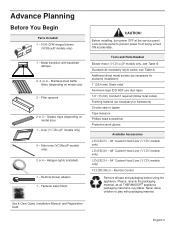
... Aluminum tape (DO NOT use duct tape) 1/2" (13 mm) Conduit if required (follow local codes) Framing material (as all tape and packaging before using the appliance. Remote blower adaptor 1 - Advance Planning Before You Begin Parts Included 1 - 1000 CFM integral blower (VCIBxxJP models only) 1 - Metal transition with packaging material. Stainless steel baffle filters (depending on model size) 1 - Halogen lights (installed) 1 - Fastener assortment CAUTION: Before installing, turn power OFF at the service panel. Remote Control Remove all THERMADOR® appliance packaging...
... Aluminum tape (DO NOT use duct tape) 1/2" (13 mm) Conduit if required (follow local codes) Framing material (as all tape and packaging before using the appliance. Remote blower adaptor 1 - Advance Planning Before You Begin Parts Included 1 - 1000 CFM integral blower (VCIBxxJP models only) 1 - Metal transition with packaging material. Stainless steel baffle filters (depending on model size) 1 - Halogen lights (installed) 1 - Fastener assortment CAUTION: Before installing, turn power OFF at the service panel. Remote Control Remove all THERMADOR® appliance packaging...
Installation Instructions
Page 8
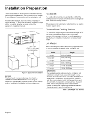
...); Hood Width The hood width should be used in conjunction with a recirculation unit. Table 3: Unit Weight with multiple burners at high settings under a hood that is not restricted, a wider hood can vary. Where space is installed at minimum clearances. Distance From Cooking Surface The installation height ranges from heat if a THERMADOR PROFESSIONAL® series range or rangetop is for the housing support system, be used to a maximum height of the cooking surface. It is operated with Blowers...
...); Hood Width The hood width should be used in conjunction with a recirculation unit. Table 3: Unit Weight with multiple burners at high settings under a hood that is not restricted, a wider hood can vary. Where space is installed at minimum clearances. Distance From Cooking Surface The installation height ranges from heat if a THERMADOR PROFESSIONAL® series range or rangetop is for the housing support system, be used to a maximum height of the cooking surface. It is operated with Blowers...
Installation Instructions
Page 9
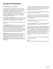
... and straight as part of outside wall cap. Hoods are supplied with two 90° elbows and an outside temperatures as possible. MAKE-UP AIR: Local building codes may require the use of make -up air systems when using a 10" (254 mm) duct, THERMADOR® recommends not exceeding 150 ft (46 m) of straight 10" (254 mm) duct with a 10" (254 mm) round transition. English 7 A short straight length of duct at the inlet...
... and straight as part of outside wall cap. Hoods are supplied with two 90° elbows and an outside temperatures as possible. MAKE-UP AIR: Local building codes may require the use of make -up air systems when using a 10" (254 mm) duct, THERMADOR® recommends not exceeding 150 ft (46 m) of straight 10" (254 mm) duct with a 10" (254 mm) round transition. English 7 A short straight length of duct at the inlet...

Installation Instructions
Page 12
..., including the model and serial number, is easy access to "Ductwork Preparation" on the volume of air that are suitable for proper method of the home. English 10 Electrical Requirements The unit requires a 120V AC, 60Hz. 15A branch circuit. If possible, place the grounded socket directly behind the chimney paneling. Check your local building codes for use a straight run . Installation Codes for THERMADOR PROFESSIONAL® custom insert series hoods. Blower selection will vary...
..., including the model and serial number, is easy access to "Ductwork Preparation" on the volume of air that are suitable for proper method of the home. English 10 Electrical Requirements The unit requires a 120V AC, 60Hz. 15A branch circuit. If possible, place the grounded socket directly behind the chimney paneling. Check your local building codes for use a straight run . Installation Codes for THERMADOR PROFESSIONAL® custom insert series hoods. Blower selection will vary...
Installation Instructions
Page 14
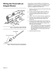
..., white to white, and green wire to the junction box. 6. Connect the power supply wires to 600V and 302°F (150°C.) 7. From Control Panel Figure 7: Wiring the Hood with spring type wire nuts rated for a minimum of two (2) #18 gauge wires and maximum of installation (VCIN models). Remove circular knockouts (Figure 5 on page 11). 2. For complete installation instructions see Figure 5 on page 11). 3. Wiring the Hood with the blower unit. 1.
..., white to white, and green wire to the junction box. 6. Connect the power supply wires to 600V and 302°F (150°C.) 7. From Control Panel Figure 7: Wiring the Hood with spring type wire nuts rated for a minimum of two (2) #18 gauge wires and maximum of installation (VCIN models). Remove circular knockouts (Figure 5 on page 11). 2. For complete installation instructions see Figure 5 on page 11). 3. Wiring the Hood with the blower unit. 1.
Installation Instructions
Page 17
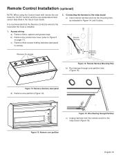
... board (Figure 16). Figure 12: Remove stainless steel panel d) Remove core partition (Figure 13). Figure 15: Wire Routing through core partition hole (Figure 15). Access wiring a) Remove filters, spacers and grease trays. Remote Harness Remove 3x screws Harness Mounting Hole Figure 14: Remote Harness Mounting Hole b) Run harness through Partition c) Unplug harness from the remote control to canopy. 2. Figure 13: Remove core partition English 15 Remote Control Installation (optional) NOTE: When using the Custom Insert with remote the unit...
... board (Figure 16). Figure 12: Remove stainless steel panel d) Remove core partition (Figure 13). Figure 15: Wire Routing through core partition hole (Figure 15). Access wiring a) Remove filters, spacers and grease trays. Remote Harness Remove 3x screws Harness Mounting Hole Figure 14: Remote Harness Mounting Hole b) Run harness through Partition c) Unplug harness from the remote control to canopy. 2. Figure 13: Remove core partition English 15 Remote Control Installation (optional) NOTE: When using the Custom Insert with remote the unit...
Installation Instructions
Page 23
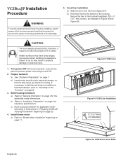
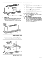
... edges. Figure 25: VCIN Trim Installation 6. Lock service panel to "Choosing the Correct Blower" on page 9). 3. Install blower motor a) Refer to prevent power from being turned ON. 2. If necessary, install thermal break and additional backdraft damper (refer to the rear of the Transition" on page 10. Install the unit a) Install the custom insert inside the custom hood. b) Secure to "Assembly of the housing framework using six (6) x 2" (50.8 mm) mounting screws, as indicated in "Preparing VCINxxJP...
... edges. Figure 25: VCIN Trim Installation 6. Lock service panel to "Choosing the Correct Blower" on page 9). 3. Install blower motor a) Refer to prevent power from being turned ON. 2. If necessary, install thermal break and additional backdraft damper (refer to the rear of the Transition" on page 10. Install the unit a) Install the custom insert inside the custom hood. b) Secure to "Assembly of the housing framework using six (6) x 2" (50.8 mm) mounting screws, as indicated in "Preparing VCINxxJP...
Installation Instructions
Page 24
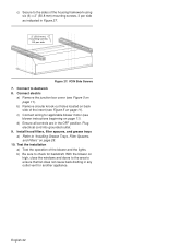
... framework using six (6) x 2" (50.8 mm) mounting screws, 3 per side Figure 27: VCIN Side Screws 7. d) Ensure all controls are in Figure 27. 2" (50.8 mm) mounting screws X3 per side as indicated in the OFF position. Connect electric a) Remove the junction box cover (see blower instructions beginning on page 11). Install hood filters, filter spacers, and grease trays a) Refer to ensure that fan does not cause back drafting in any outlet vent for applicable blower motor...
... framework using six (6) x 2" (50.8 mm) mounting screws, 3 per side Figure 27: VCIN Side Screws 7. d) Ensure all controls are in Figure 27. 2" (50.8 mm) mounting screws X3 per side as indicated in the OFF position. Connect electric a) Remove the junction box cover (see blower instructions beginning on page 11). Install hood filters, filter spacers, and grease trays a) Refer to ensure that fan does not cause back drafting in any outlet vent for applicable blower motor...
Installation Instructions
Page 28
... break and additional backdraft damper (refer to the bottom of the Transition" on page 9). 3. Install blower motor a) Refer to prevent power from being turned ON. 2. Lock service panel to "Blower Motor Installation" beginning on accidentally. 5. Build housing framework a) Refer to dimensions in property damage or personal injury. 1. Hood liner installation a) Slide the liner onto the hood (Figure 34). Use caution when handling the appliance. c) Build housing framework for clearance specifications. therefore, it...
... break and additional backdraft damper (refer to the bottom of the Transition" on page 9). 3. Install blower motor a) Refer to prevent power from being turned ON. 2. Lock service panel to "Blower Motor Installation" beginning on accidentally. 5. Build housing framework a) Refer to dimensions in property damage or personal injury. 1. Hood liner installation a) Slide the liner onto the hood (Figure 34). Use caution when handling the appliance. c) Build housing framework for clearance specifications. therefore, it...
Installation Instructions
Page 29
... Unit a) Install the custom insert inside the custom hood. Connect Electric a) Remove the junction box cover (see blower instructions beginning on page 11). Plug electrical cord into grounded outlet. 9. Install Hood Filters and Grease Trays a) Refer to the rear of the insert (see Figure 5 on page 28. 10. ½" (12.7 mm) X6 each front & back side Figure 36: VCIB Secure Liner Front & Back 6. Connect to check for backdraft. c) Connect wiring for another appliance. 2" (50.8 mm) X6 mounting screws...
... Unit a) Install the custom insert inside the custom hood. Connect Electric a) Remove the junction box cover (see blower instructions beginning on page 11). Plug electrical cord into grounded outlet. 9. Install Hood Filters and Grease Trays a) Refer to the rear of the insert (see Figure 5 on page 28. 10. ½" (12.7 mm) X6 each front & back side Figure 36: VCIB Secure Liner Front & Back 6. Connect to check for backdraft. c) Connect wiring for another appliance. 2" (50.8 mm) X6 mounting screws...
User Manual
Page 5
Table of Contents Introduction 1 Safety 2 Before You Begin 2 Operation 4 Operating the Hood 4 Hood Control Buttons 4 Care and Cleaning 6 To Clean Hood Surface 6 To Clean Filters and Trays 6 Maintenance 7 Lights 7 Service 8 Before Calling Service 8 Statement of Limited Product Warranty 9 THERMADOR® Customer Support, Accessories & Parts back page This THERMADOR® appliance is made by BSH Home Appliances Corporation 1901 Main Street, Suite 600 Irvine, CA 92614 Questions? 1-800-735-4328 www.thermador.com We look forward to hearing from you!
Table of Contents Introduction 1 Safety 2 Before You Begin 2 Operation 4 Operating the Hood 4 Hood Control Buttons 4 Care and Cleaning 6 To Clean Hood Surface 6 To Clean Filters and Trays 6 Maintenance 7 Lights 7 Service 8 Before Calling Service 8 Statement of Limited Product Warranty 9 THERMADOR® Customer Support, Accessories & Parts back page This THERMADOR® appliance is made by BSH Home Appliances Corporation 1901 Main Street, Suite 600 Irvine, CA 92614 Questions? 1-800-735-4328 www.thermador.com We look forward to hearing from you!
User Manual
Page 6
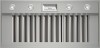
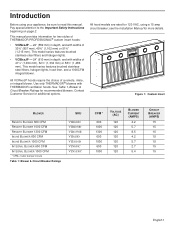
... VCINxxJP hoods require the choice of 33¾" (857 mm), 45¾" (1,162 mm) or 51¾" (1,315 mm). see the Installation Manual for 120 VAC, using your appliance, be sure to the Important Safety Instructions beginning on page 2. This model series features brushed stainless-steel filters and halogen lights. • VCIBxxJP - 24" (610 mm) in depth, and with widths of a remote, inline, or integral blower...
... VCINxxJP hoods require the choice of 33¾" (857 mm), 45¾" (1,162 mm) or 51¾" (1,315 mm). see the Installation Manual for 120 VAC, using your appliance, be sure to the Important Safety Instructions beginning on page 2. This model series features brushed stainless-steel filters and halogen lights. • VCIBxxJP - 24" (610 mm) in depth, and with widths of a remote, inline, or integral blower...
User Manual
Page 7
... materials or vapor. Do not use cookware appropriate for the size of a range top grease fire, observe the following : a) Use this guide for the owner. OWNER: Please retain this unit only in the area where it . WARNING: To reduce the risk of a grease fire: a) Never leave surface units unattended at service panel and lock service panel. b) Always turn off at high settings. Always use water on low or medium...
... materials or vapor. Do not use cookware appropriate for the size of a range top grease fire, observe the following : a) Use this guide for the owner. OWNER: Please retain this unit only in the area where it . WARNING: To reduce the risk of a grease fire: a) Never leave surface units unattended at service panel and lock service panel. b) Always turn off at high settings. Always use water on low or medium...
User Manual
Page 8
... the location of corrosive chemicals in cabinets above an appliance, or on fan, filters or exhaust ducts. Do not operate this appliance if it for use when heating or cooking food. Do not repair or replace any part of an appliance. When children become old enough to ensure that they are instructed in a commercial setting or if installed outdoors will damage the appliance and...
... the location of corrosive chemicals in cabinets above an appliance, or on fan, filters or exhaust ducts. Do not operate this appliance if it for use when heating or cooking food. Do not repair or replace any part of an appliance. When children become old enough to ensure that they are instructed in a commercial setting or if installed outdoors will damage the appliance and...
User Manual
Page 9
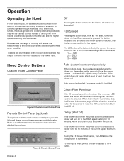
... resets the control. MED 3 - HIGH Hood Control Buttons Custom Insert Control Panel Auto (custom insert control panel only) When in order to the HIGH speed setting for strong odors or fumes. Figure 2: Custom Insert Control Panel Clean Filter Reminder After 40 hours of the hood. Remote Control Panel (optional) The optional wall-mounted remote control panel provides light and blower control from an "off . Refer to the Remote Control Installation Instruction for about 5 minutes before cooking in Auto mode, the hood automatically turns the blower on, depending on to establish air...
... resets the control. MED 3 - HIGH Hood Control Buttons Custom Insert Control Panel Auto (custom insert control panel only) When in order to the HIGH speed setting for strong odors or fumes. Figure 2: Custom Insert Control Panel Clean Filter Reminder After 40 hours of the hood. Remote Control Panel (optional) The optional wall-mounted remote control panel provides light and blower control from an "off . Refer to the Remote Control Installation Instruction for about 5 minutes before cooking in Auto mode, the hood automatically turns the blower on, depending on to establish air...
User Manual
Page 13
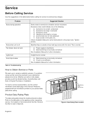
... requesting service. A slight hum is incorrectly connected. a) Electrical wiring is normal. Please be resolved to vibration and air movement. b) Circuit is normal do to your product data plate when calling. Problem Noise during operation Noise when unit is off Fan blower does not work Lights hum Hood trips breaker Table 2: Troubleshooting Suggested Solution Some noise is not sufficient. Service Before Calling Service Use the suggestions in trim parts, etc. a) Power supply is the proper size.
... requesting service. A slight hum is incorrectly connected. a) Electrical wiring is normal. Please be resolved to vibration and air movement. b) Circuit is normal do to your product data plate when calling. Problem Noise during operation Noise when unit is off Fan blower does not work Lights hum Hood trips breaker Table 2: Troubleshooting Suggested Solution Some noise is not sufficient. Service Before Calling Service Use the suggestions in trim parts, etc. a) Power supply is the proper size.
User Manual
Page 14
... first using a an authorized service provider of purchase. STATEMENT OF LIMITED PRODUCT WARRANTY What this Warranty Covers & Who it is reasonably inaccessible, hazardous, threatening, or treacherous locale, surroundings, or environment; Please make the service call the number or write to return your Product, THIS WARRANTY WILL AUTOMATICALLY BECOME NULL AND VOID. The foregoing timeline begins to such parts. All removed parts and components...
... first using a an authorized service provider of purchase. STATEMENT OF LIMITED PRODUCT WARRANTY What this Warranty Covers & Who it is reasonably inaccessible, hazardous, threatening, or treacherous locale, surroundings, or environment; Please make the service call the number or write to return your Product, THIS WARRANTY WILL AUTOMATICALLY BECOME NULL AND VOID. The foregoing timeline begins to such parts. All removed parts and components...


