Service Manual
Page 1
... RMS power, with no sound output. While holding down DIMMER, press ?/1. SERVICE MANUAL Ver. 1.1 2007.03 STR-K790 US Model Canadian Model AEP Model UK Model • STR-K790 is the tuner and the amplifier section in any AM station, turn off the receiver. Inputs Analog Sensitivity: 800... reset the scale to rated output. FM STEREO/FM-AM RECEIVER 9-887-542-02 2007C16-1 © 2007.03 Sony Corporation Home Audio Division Published by Sony Techno Create Corporation SPECIFICATIONS AUDIO POWER SPECIFICATIONS POWER OUTPUT AND TOTAL HARMONIC DISTORTION: (Models of DTS, Inc. Depending on...
... RMS power, with no sound output. While holding down DIMMER, press ?/1. SERVICE MANUAL Ver. 1.1 2007.03 STR-K790 US Model Canadian Model AEP Model UK Model • STR-K790 is the tuner and the amplifier section in any AM station, turn off the receiver. Inputs Analog Sensitivity: 800... reset the scale to rated output. FM STEREO/FM-AM RECEIVER 9-887-542-02 2007C16-1 © 2007.03 Sony Corporation Home Audio Division Published by Sony Techno Create Corporation SPECIFICATIONS AUDIO POWER SPECIFICATIONS POWER OUTPUT AND TOTAL HARMONIC DISTORTION: (Models of DTS, Inc. Depending on...
Service Manual
Page 2
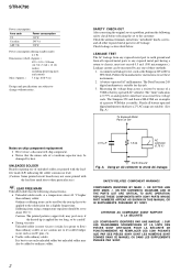
... low-voltage scale. A. Using an AC voltmeter to change without notice. REPLACE THESE COMPONENTS WITH SONY PARTS WHOSE PART NUMBERS APPEAR AS SHOWN IN THIS MANUAL OR IN SUPPLEMENTS PUBLISHED BY SONY. A battery-operated AC milliammeter. ATTENTION AU COMPOSANT AYANT RAPPORT À LA SÉCURITÉ... LES NUMÉROS SONT DONNÉS DANS CE MANUEL OU DANS LES SUPPLÉMENTS PUBLIÉS PAR SONY. 2 STR-K790 Power consumption Area code Power consumption US 210 W Canadian 290 VA AEP, UK 220 W Power consumption (during standby mode) 0.3 W Dimensions (w/h/d) (Approx.) ...
... low-voltage scale. A. Using an AC voltmeter to change without notice. REPLACE THESE COMPONENTS WITH SONY PARTS WHOSE PART NUMBERS APPEAR AS SHOWN IN THIS MANUAL OR IN SUPPLEMENTS PUBLISHED BY SONY. A battery-operated AC milliammeter. ATTENTION AU COMPOSANT AYANT RAPPORT À LA SÉCURITÉ... LES NUMÉROS SONT DONNÉS DANS CE MANUEL OU DANS LES SUPPLÉMENTS PUBLIÉS PAR SONY. 2 STR-K790 Power consumption Area code Power consumption US 210 W Canadian 290 VA AEP, UK 220 W Power consumption (during standby mode) 0.3 W Dimensions (w/h/d) (Approx.) ...
Service Manual
Page 3
... LIST 44 3 DIGITAL Board (Side A) - ...... 16 4-4. Schematic Diagram - Schematic Diagram - DIGITAL Board (3/5 20 4-8. Schematic Diagram - Printed Wiring Board - POWER Board, DCAC Board, HEADPHONE Board 34 5. STR-K790 About area codes The area code of the receiver you purchased is shown on the lower right portion of area code AA only". Rear Panel...
... LIST 44 3 DIGITAL Board (Side A) - ...... 16 4-4. Schematic Diagram - Schematic Diagram - DIGITAL Board (3/5 20 4-8. Schematic Diagram - Printed Wiring Board - POWER Board, DCAC Board, HEADPHONE Board 34 5. STR-K790 About area codes The area code of the receiver you purchased is shown on the lower right portion of area code AA only". Rear Panel...
Service Manual
Page 4
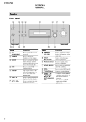
... MIC jack Function Turn to the supplied optimizer microphone for the Auto Calibration function. - Connects to adjust the volume level of selectable items appears here. STR-K790 Receiver Front panel 1 234 ?/1 VIDEO 1 IN/ PORTABLE AUDIO IN/ AUTO CAL MIC DIMMER SLEEP 2CH A.F.D. MOVIE MUSIC PHONES SECTION 1 GENERAL 5 67 8 DISPLAY AUTO CAL INPUT...
... MIC jack Function Turn to the supplied optimizer microphone for the Auto Calibration function. - Connects to adjust the volume level of selectable items appears here. STR-K790 Receiver Front panel 1 234 ?/1 VIDEO 1 IN/ PORTABLE AUDIO IN/ AUTO CAL MIC DIMMER SLEEP 2CH A.F.D. MOVIE MUSIC PHONES SECTION 1 GENERAL 5 67 8 DISPLAY AUTO CAL INPUT...
Service Manual
Page 5
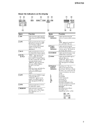
... dynamic range compression is activated. Lights up when the receiver applies Pro Logic processing to 2 channel signals in order to tune in radio stations, etc. STR-K790 About the indicators on presetting radio stations. Front Left Front Right Center (monaural) Surround Left Surround Right Surround (monaural or the surround components obtained by...
... dynamic range compression is activated. Lights up when the receiver applies Pro Logic processing to 2 channel signals in order to tune in radio stations, etc. STR-K790 About the indicators on presetting radio stations. Front Left Front Right Center (monaural) Surround Left Surround Right Surround (monaural or the surround components obtained by...
Service Manual
Page 6
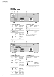
... IN jack player, etc. B ANTENNA section FM ANTENNA jack AM ANTENNA terminals Connects to the speakers and sub woofer*. * The numbers of loud jack sound. STR-K790 Rear panel US, Canadian models 12 3 4 DIGITAL OPTICAL VIDEO 2/ BD IN COAXIAL DVD IN ANTENNA AM L R AUDIO IN AUDIO IN AUDIO IN SA-CD/CD...
... IN jack player, etc. B ANTENNA section FM ANTENNA jack AM ANTENNA terminals Connects to the speakers and sub woofer*. * The numbers of loud jack sound. STR-K790 Rear panel US, Canadian models 12 3 4 DIGITAL OPTICAL VIDEO 2/ BD IN COAXIAL DVD IN ANTENNA AM L R AUDIO IN AUDIO IN AUDIO IN SA-CD/CD...
Service Manual
Page 7
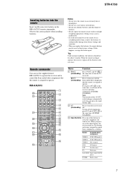
STR-K790 Inserting batteries into the remote Insert two R6 (size-AA) batteries in tuner 7 When the remote no longer operates the receiver, replace all components, press ?/1 ... of the AV ?/1 switch changes automatically each time you want to use the supplied remote RM-AAU013 to operate the receiver and to control the Sony audio/video components that the remote is assigned to use a new battery with new ones. When you press ?/1 (B) at (on/standby) the same time to...
STR-K790 Inserting batteries into the remote Insert two R6 (size-AA) batteries in tuner 7 When the remote no longer operates the receiver, replace all components, press ?/1 ... of the AV ?/1 switch changes automatically each time you want to use the supplied remote RM-AAU013 to operate the receiver and to control the Sony audio/video components that the remote is assigned to use a new battery with new ones. When you press ?/1 (B) at (on/standby) the same time to...
Service Manual
Page 8
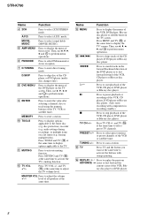
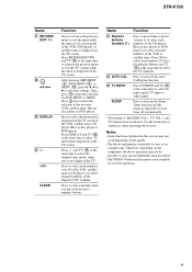
... scan a station. erasing multiple titles). and TV (O) at the same time to display options applicable to perform menu operations. Then, use V, v, B, b and to the TV. STR-K790 Name Function D 2CH Press to enter direct tuning mode. PRESET +/- G D.TUNING Press to select 2CH STEREO mode. level of the VCR, CD player or Blu...
... scan a station. erasing multiple titles). and TV (O) at the same time to display options applicable to perform menu operations. Then, use V, v, B, b and to the TV. STR-K790 Name Function D 2CH Press to enter direct tuning mode. PRESET +/- G D.TUNING Press to select 2CH STEREO mode. level of the VCR, CD player or Blu...
Service Manual
Page 9
... or CD player or to select channel numbers of the TV. Press TV INPUT and TV (O) at the same time to select the TV channels. STR-K790 Name Q RETURN/ EXIT O R V/v/B/b S DISPLAY T -/->10/x CLEAR Function Press to return to the previous menu or exit the menu while the menu or on-screen guide...
... or CD player or to select channel numbers of the TV. Press TV INPUT and TV (O) at the same time to select the TV channels. STR-K790 Name Q RETURN/ EXIT O R V/v/B/b S DISPLAY T -/->10/x CLEAR Function Press to return to the previous menu or exit the menu while the menu or on-screen guide...
Service Manual
Page 10
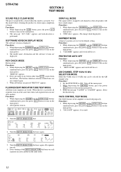
STR-K790 SECTION 2 TEST MODE SOUND FIELD CLEAR MODE The preset sound field is cleared when this mode is displayed. SOFTWARE VERSION DISPLAY MODE The software version ...
STR-K790 SECTION 2 TEST MODE SOUND FIELD CLEAR MODE The preset sound field is cleared when this mode is displayed. SOFTWARE VERSION DISPLAY MODE The software version ...
Service Manual
Page 11
... Front Left 1. DCAC board Checking Connect front left speaker, and the display will be test tone sound output from front left speaker of test tone) STR-K790 11 Afterward, press the DIMMER to 255 (depends on loudness of the receiver and AUTO CAL microphone. Turn MASTER VOLUME jog, there will change accordingly...
... Front Left 1. DCAC board Checking Connect front left speaker, and the display will be test tone sound output from front left speaker of test tone) STR-K790 11 Afterward, press the DIMMER to 255 (depends on loudness of the receiver and AUTO CAL microphone. Turn MASTER VOLUME jog, there will change accordingly...
Service Manual
Page 12
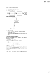
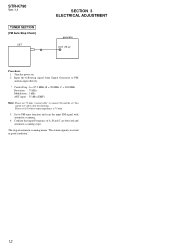
... on. 2. Confirm that input Frequency of automatic scanning means "The station signal is 75 ohm. 3. The stop of A, B and C are detected and automatic scanning stops. STR-K790 Ver. 1.1 TUNER SECTION [FM Auto Stop Check] SET SECTION 3 ELECTRICAL ADJUSTMENT generator OUT (75 Ω) Procedure: 1. Set to FM antenna input directly. * Carrier Freq : A = 87...
... on. 2. Confirm that input Frequency of automatic scanning means "The station signal is 75 ohm. 3. The stop of A, B and C are detected and automatic scanning stops. STR-K790 Ver. 1.1 TUNER SECTION [FM Auto Stop Check] SET SECTION 3 ELECTRICAL ADJUSTMENT generator OUT (75 Ω) Procedure: 1. Set to FM antenna input directly. * Carrier Freq : A = 87...
Service Manual
Page 13
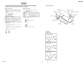
... 1 IC1905 9 (MCLK1) 72 ns 1 V/DIV, 40 ns/DIV 2 IC1101 id (X1) 3.5 Vp-p 41.6 ns 1 V/DIV, 20 ns/DIV 3 IC1301 ws (XIN) 4.2 Vp-p STR-K790 81.4 ns 1 V/DIV, 40 ns/DIV 4.2 Vp-p 13 13 Note: • X : parts extracted from the component side. • a : Through hole. • f : internal... designation. No mark : FM • Voltages are omitted. • Circuit Boards Location STANDBY board POWER board DCAC board HEADPHONE board DISPLAY board STR-K790 HDMI SW board (AEP,UK) HDMI BRIDGE board (AEP,UK) DIGITAL board MAIN board • Waveforms - der no-signal (detuned) conditions....
... 1 IC1905 9 (MCLK1) 72 ns 1 V/DIV, 40 ns/DIV 2 IC1101 id (X1) 3.5 Vp-p 41.6 ns 1 V/DIV, 20 ns/DIV 3 IC1301 ws (XIN) 4.2 Vp-p STR-K790 81.4 ns 1 V/DIV, 40 ns/DIV 4.2 Vp-p 13 13 Note: • X : parts extracted from the component side. • a : Through hole. • f : internal... designation. No mark : FM • Voltages are omitted. • Circuit Boards Location STANDBY board POWER board DCAC board HEADPHONE board DISPLAY board STR-K790 HDMI SW board (AEP,UK) HDMI BRIDGE board (AEP,UK) DIGITAL board MAIN board • Waveforms - der no-signal (detuned) conditions....
Service Manual
Page 15
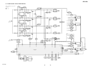
DISPLAY/POWER SECTION - STR-K790 • R-CH is omitted due to same as L-CH. • Signal Path : FM L IC501 POWER AMP +V OUT2 12 8 IN2 NF2 9 Q501,502 LIMITER Q503 BOOSTER -V ... F2 D1001 IC1904 3 +3.3V REG 1 D910-913 F901 AC IN Q911 AC DET D914 D915 T900(AEP,UK) T902(US,CND) Q901 RELAY DRIVE RY901 STR-K790 15 15 BLOCK DIAGRAM - 4-2.
DISPLAY/POWER SECTION - STR-K790 • R-CH is omitted due to same as L-CH. • Signal Path : FM L IC501 POWER AMP +V OUT2 12 8 IN2 NF2 9 Q501,502 LIMITER Q503 BOOSTER -V ... F2 D1001 IC1904 3 +3.3V REG 1 D910-913 F901 AC IN Q911 AC DET D914 D915 T900(AEP,UK) T902(US,CND) Q901 RELAY DRIVE RY901 STR-K790 15 15 BLOCK DIAGRAM - 4-2.
Service Manual
Page 16
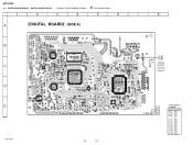
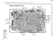
... BOARD (SIDE A) - • See page 13 for Circuit Boards Location. :Uses unleaded solder. 1 2 3 4 5 6 7 8 A DIGITAL BOARD (SIDE A) R1943 C1913 B C D E STR-K790 R1096 FB1350 R1318 C1315 R1321 R1253 FB1306 IC1301 R1313 R1312 R1311 R1555 C1031 FB1310 C1301 R1557 RB1500 C1302 R1301 C1304 R1304 D1302 JR1005 R1303 R1325 ...• Semiconductor Location Ref. No. Location D1001 B-6 D1109 C-7 D1301 C-3 D1302 C-2 IC1101 D-6 IC1111 C-7 IC1131 E-6 IC1301 B-3 IC1303 C-3 IC1401 E-2 IC1452 D-3 IC1502 C-4 IC1503 D-5 IC1905 C-4 16 16 PRINTED WIRING BOARD - STR-K790 4-3.
... BOARD (SIDE A) - • See page 13 for Circuit Boards Location. :Uses unleaded solder. 1 2 3 4 5 6 7 8 A DIGITAL BOARD (SIDE A) R1943 C1913 B C D E STR-K790 R1096 FB1350 R1318 C1315 R1321 R1253 FB1306 IC1301 R1313 R1312 R1311 R1555 C1031 FB1310 C1301 R1557 RB1500 C1302 R1301 C1304 R1304 D1302 JR1005 R1303 R1325 ...• Semiconductor Location Ref. No. Location D1001 B-6 D1109 C-7 D1301 C-3 D1302 C-2 IC1101 D-6 IC1111 C-7 IC1131 E-6 IC1301 B-3 IC1303 C-3 IC1401 E-2 IC1452 D-3 IC1502 C-4 IC1503 D-5 IC1905 C-4 16 16 PRINTED WIRING BOARD - STR-K790 4-3.
Service Manual
Page 17
... (Page 31) for Circuit Boards Location. :Uses unleaded solder. Location D1003 D-3 D1004 D-3 D1107 C-6 D1108 C-6 D1110 C-6 D1111 C-7 D1501 C-3 D1502 C-3 D1503 D-3 IC1001 E-3 IC1031 B-7 IC1351 C-2 IC1901 B-7 IC1902 B-5 IC1904 B-6 STR-K790 DIGITAL BOARD (SIDE B) STANDBY BOARD C CNP801 (Page 26) AM TUNER FM 75 COAXIAL AEP,UK HDMI BRIDGE A BOARD CNS199 (Page 23) HS1903 HS1901 CL026 IC1031...
... (Page 31) for Circuit Boards Location. :Uses unleaded solder. Location D1003 D-3 D1004 D-3 D1107 C-6 D1108 C-6 D1110 C-6 D1111 C-7 D1501 C-3 D1502 C-3 D1503 D-3 IC1001 E-3 IC1031 B-7 IC1351 C-2 IC1901 B-7 IC1902 B-5 IC1904 B-6 STR-K790 DIGITAL BOARD (SIDE B) STANDBY BOARD C CNP801 (Page 26) AM TUNER FM 75 COAXIAL AEP,UK HDMI BRIDGE A BOARD CNS199 (Page 23) HS1903 HS1901 CL026 IC1031...

Service Manual
Page 21
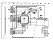
4-8. DIGITAL BOARD (4/5) - SCHEMATIC DIAGRAM - STR-K790 1 2 3 4 5 6 7 8 9 10 11 MAIN BOARD STANDBY (3/4) BOARD A CNP504 D (Page 29) CNP801 C (Page 28) 1 +R2 2 STOP 3 STDBY GND 4 +9V (STDBY) 5 PW_RY 6 +R4 7 R4 GND H/P_RY H/P CTRL C/REAR/... 95 96 98 a1 a2 a5 a4 a6 a3 a7 a8 b8 a9 b1 b2 b3 b5 b4 b6 b7 14 DIGITAL BOARD (5/5) (Page 22) STR-K790 21 21
4-8. DIGITAL BOARD (4/5) - SCHEMATIC DIAGRAM - STR-K790 1 2 3 4 5 6 7 8 9 10 11 MAIN BOARD STANDBY (3/4) BOARD A CNP504 D (Page 29) CNP801 C (Page 28) 1 +R2 2 STOP 3 STDBY GND 4 +9V (STDBY) 5 PW_RY 6 +R4 7 R4 GND H/P_RY H/P CTRL C/REAR/... 95 96 98 a1 a2 a5 a4 a6 a3 a7 a8 b8 a9 b1 b2 b3 b5 b4 b6 b7 14 DIGITAL BOARD (5/5) (Page 22) STR-K790 21 21

Service Manual
Page 23
IC5001 IC5002 IC5003 IC5004 IC5005 IC5006 Location C-3 C-4 C-4 B-4 B-4 C-2 1 F STR-K790 B199 1-873-511- 23 23 STR-K790 PRINTED WIRING BOARDS - 4-10. HDMI SW BOARD, HDMI BRIDGE BOARD (AEP, UK only) - • See page 13 for Circuit Boards Location. :Uses unleaded solder. 1 2 3 4 5 6 7 8 AEP,...
IC5001 IC5002 IC5003 IC5004 IC5005 IC5006 Location C-3 C-4 C-4 B-4 B-4 C-2 1 F STR-K790 B199 1-873-511- 23 23 STR-K790 PRINTED WIRING BOARDS - 4-10. HDMI SW BOARD, HDMI BRIDGE BOARD (AEP, UK only) - • See page 13 for Circuit Boards Location. :Uses unleaded solder. 1 2 3 4 5 6 7 8 AEP,...
Service Manual
Page 24
... SW BOARD, HDMI BRIDGE BOARD (AEP, UK only) - • See page 37 for IC Block Diagrams. AEP,UK VIDEO 2/BD IN STR-K790 HDMI SW BOARD R5047 0 R5068 100k TP5016 R5016 0 R5017 0 CN5001 19P CN5002 19P R5048 0 R5069 100k R5018 1k R5019 0 R5020 0 C5002 0.01 TP5001 C5011 0.01 ...
... SW BOARD, HDMI BRIDGE BOARD (AEP, UK only) - • See page 37 for IC Block Diagrams. AEP,UK VIDEO 2/BD IN STR-K790 HDMI SW BOARD R5047 0 R5068 100k TP5016 R5016 0 R5017 0 CN5001 19P CN5002 19P R5048 0 R5069 100k R5018 1k R5019 0 R5020 0 C5002 0.01 TP5001 C5011 0.01 ...
Service Manual
Page 25
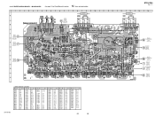
MAIN BOARD - • See page 13 for Circuit Boards Location. :Uses unleaded solder. No. STR-K790 Ver. 1.1 1 A B C DCAC E BOARD CN2001 (4pin-6pin) (Page 33) D DIGITAL F BOARD CNS501 (Page 17) E DIGITAL G F BOARD CNS502 (Page 17) G H 2 3 4 5 6 7 8 9 10 11 12 ... H-7 Ref. No. Q706 Q707 Q708 Q751 Q752 Q753 Q754 Q755 Q756 Q801 Q851 Q852 Q881 Q882 Q883 Location G-4 G-3 C-6 G-5 H-6 H-5 H-6 G-6 G-5 F-14 F-11 E-9 E-12 F-12 F-12 STR-K790 25 25 No. No. No. Location Ref. Q605 Q606 Q607 Q608 Q651 Q652 Q653 Q654 Q655 Q656 Q657 Q701 Q702 Q703 Q704 Q705 Location G-10...
MAIN BOARD - • See page 13 for Circuit Boards Location. :Uses unleaded solder. No. STR-K790 Ver. 1.1 1 A B C DCAC E BOARD CN2001 (4pin-6pin) (Page 33) D DIGITAL F BOARD CNS501 (Page 17) E DIGITAL G F BOARD CNS502 (Page 17) G H 2 3 4 5 6 7 8 9 10 11 12 ... H-7 Ref. No. Q706 Q707 Q708 Q751 Q752 Q753 Q754 Q755 Q756 Q801 Q851 Q852 Q881 Q882 Q883 Location G-4 G-3 C-6 G-5 H-6 H-5 H-6 G-6 G-5 F-14 F-11 E-9 E-12 F-12 F-12 STR-K790 25 25 No. No. No. Location Ref. Q605 Q606 Q607 Q608 Q651 Q652 Q653 Q654 Q655 Q656 Q657 Q701 Q702 Q703 Q704 Q705 Location G-10...