
Limited Warranty (US Only)
Page 1
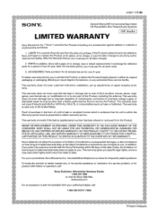
... of purchase, if this Product (including any part of the Product, including the antenna. has established telephone numbers for one (1) year. 4-557-172-02 General Stereo/Hifi Components/Tape Decks ® CD Players/Mini Disc Players/Audio Systems Hifi Audio LIMITED WARRANTY Sony Electronics Inc. ("Sony") warrants this Product is within the Warranty period...
... of purchase, if this Product (including any part of the Product, including the antenna. has established telephone numbers for one (1) year. 4-557-172-02 General Stereo/Hifi Components/Tape Decks ® CD Players/Mini Disc Players/Audio Systems Hifi Audio LIMITED WARRANTY Sony Electronics Inc. ("Sony") warrants this Product is within the Warranty period...
Marketing Specifications (HTDDW700 Home Theater System)
Page 2
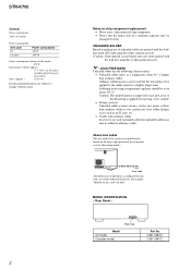
...-222-7669 • www.sony.com Last Updated: 04/04/2006 HT-DDW700 Component Home Theater System Specifications Receiver Audio Audio Power Output: 800W (133w x 5 + 135w (1KHz, 10% THD)) Inputs and Outputs Analog Audio Input(s): 4 (Rear) Antenna Terminal(s): Yes (FM 75ohms, AM Loop) Coaxial ...108.0 MHz Station Preset(s): 10 AM, 20 FM Tuner Type: AM, FM Front Speaker Speaker Speaker Type: Enclosure- Nonmetric weights and measures are trademarks of Dolby Laboratories. All other are approximate. Reproduction in whole or in part without notice. Bass Reflex (Ported) Woofer(s): ...
...-222-7669 • www.sony.com Last Updated: 04/04/2006 HT-DDW700 Component Home Theater System Specifications Receiver Audio Audio Power Output: 800W (133w x 5 + 135w (1KHz, 10% THD)) Inputs and Outputs Analog Audio Input(s): 4 (Rear) Antenna Terminal(s): Yes (FM 75ohms, AM Loop) Coaxial ...108.0 MHz Station Preset(s): 10 AM, 20 FM Tuner Type: AM, FM Front Speaker Speaker Speaker Type: Enclosure- Nonmetric weights and measures are trademarks of Dolby Laboratories. All other are approximate. Reproduction in whole or in part without notice. Bass Reflex (Ported) Woofer(s): ...

Operating Instructions
Page 2
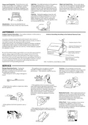
... equipment does cause harmful interference to radio or television reception, which the receiver is intended to alert the user to provide reasonable protection against harmful interference in this manual could void your authority to Part 15 of the FCC Rules. Connect the equipment into an outlet on ... to constitute a risk of electric shock to correct the interference by one or more of the following measures: Reorient or relocate the receiving antenna. dispose of the apparatus with general house waste; Consult the dealer or an experienced radio/TV technician for proper grounding and, ...
... equipment does cause harmful interference to radio or television reception, which the receiver is intended to alert the user to provide reasonable protection against harmful interference in this manual could void your authority to Part 15 of the FCC Rules. Connect the equipment into an outlet on ... to constitute a risk of electric shock to correct the interference by one or more of the following measures: Reorient or relocate the receiving antenna. dispose of the apparatus with general house waste; Consult the dealer or an experienced radio/TV technician for proper grounding and, ...
Operating Instructions
Page 4
Table of Contents Getting Started Description and location of parts 5 1: Installing speakers 12 2: Connecting speakers 14 3: Connecting the audio/video components 15 4: Connecting the antennas 18 5: Preparing the receiver and the remote 19 6: Calibrating the appropriate settings automatically (AUTO CALIBRATION) 20 ... sound field 39 Using only the front speakers and sub woofer (2CH STEREO) 42 Resetting sound fields to the initial settings 42 Tuner Operations Listening to FM/AM radio 43 Presetting radio stations 44 Other Operation Switching the audio input...
Table of Contents Getting Started Description and location of parts 5 1: Installing speakers 12 2: Connecting speakers 14 3: Connecting the audio/video components 15 4: Connecting the antennas 18 5: Preparing the receiver and the remote 19 6: Calibrating the appropriate settings automatically (AUTO CALIBRATION) 20 ... sound field 39 Using only the front speakers and sub woofer (2CH STEREO) 42 Resetting sound fields to the initial settings 42 Tuner Operations Listening to FM/AM radio 43 Presetting radio stations 44 Other Operation Switching the audio input...
Operating Instructions
Page 5
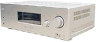
...on or off automatically (page 6, 48). Turn to select the input source to select 2CH STEREO mode (page 34). Press to adjust the brightness of selectable items appears here (page 6). Receives signals from remote commander. mode (page 38). Press to both digital and analog jacks (page... 47). papels Bugle° Description and location of parts Receiver Front panel -21 4 t 5 6 Name 1 ii(1) 121 DIMMER 3 SLEEP 4 2CH 5 Display 6 DISPLAY 7 INPUT MODE Function Press to turn the receiver on the display (page 48, 54). Press to activate the Sleep Timer function...
...on or off automatically (page 6, 48). Turn to select the input source to select 2CH STEREO mode (page 34). Press to adjust the brightness of selectable items appears here (page 6). Receives signals from remote commander. mode (page 38). Press to both digital and analog jacks (page... 47). papels Bugle° Description and location of parts Receiver Front panel -21 4 t 5 6 Name 1 ii(1) 121 DIMMER 3 SLEEP 4 2CH 5 Display 6 DISPLAY 7 INPUT MODE Function Press to turn the receiver on the display (page 48, 54). Press to activate the Sleep Timer function...
Operating Instructions
Page 56
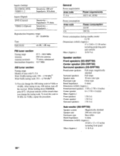
... off the receiver. Inputs (Analog) SA-CD/CD, DVD, VIDEO 1, 2 Sensitivity: 800 mV Impedance: 50 kohms Inputs (Digital) DVD (Coaxial) VIDEO 2 (Optical) Sensitivity: - Reproduction frequency range: 28 - 20,000 Hz Tone Gain levels ±6 dB, 1 dB step FM tuner section ...Power consumption 210 W 290 VA Power consumption (during standby mode) 0.2 W Dimensions (w/h/d) (Approx.) 17 x 5 6/8 x 12 1/8 inches including projecting parts and controls Mass (Approx.) 16 lb 9 oz Speaker section Front speakers (SS-MSP700) Center speaker (SS-CNP700) Surround speakers (SS-SRP700) Front/center...
... off the receiver. Inputs (Analog) SA-CD/CD, DVD, VIDEO 1, 2 Sensitivity: 800 mV Impedance: 50 kohms Inputs (Digital) DVD (Coaxial) VIDEO 2 (Optical) Sensitivity: - Reproduction frequency range: 28 - 20,000 Hz Tone Gain levels ±6 dB, 1 dB step FM tuner section ...Power consumption 210 W 290 VA Power consumption (during standby mode) 0.2 W Dimensions (w/h/d) (Approx.) 17 x 5 6/8 x 12 1/8 inches including projecting parts and controls Mass (Approx.) 16 lb 9 oz Speaker section Front speakers (SS-MSP700) Center speaker (SS-CNP700) Surround speakers (SS-SRP700) Front/center...
Operating Instructions
Page 63
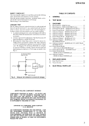
...servicing to the National Electrical Code An outdoor antenna system should not be sure the service technician has used replacement parts specified by Sony that have fallen into the appliance through openings as opening or removing covers may result in the operating instructions. Antenna...Attachments - Refer all servicing to rain or water. - This will often require extensive work by Sony. Use a cloth lightly dampened with such power lines or circuits. Safety Check - All SETS RECEIVE OUR OK .SAFETY CHECK. Route the power cord so that are required, be located in contact...
...servicing to the National Electrical Code An outdoor antenna system should not be sure the service technician has used replacement parts specified by Sony that have fallen into the appliance through openings as opening or removing covers may result in the operating instructions. Antenna...Attachments - Refer all servicing to rain or water. - This will often require extensive work by Sony. Use a cloth lightly dampened with such power lines or circuits. Safety Check - All SETS RECEIVE OUR OK .SAFETY CHECK. Route the power cord so that are required, be located in contact...
Operating Instructions
Page 65
...part not available from state to any authorized Sony service facility. To obtain warranty service, you . This warranty is valid only in material or workmanship as fuses or batteries). REPAIR OR REPLACEMENT AS PROVIDED UNDER THIS WARRANTY IS THE EXCLUSIVE REMEDY OF THE CONSUMER. 4-557-173-02 SONY® General Stereo.../Hifi Components/Tape Decks CD Players/Mini Disc Players/Audio Systems Hifi Audio LIMITED WARRANTY Sony Electronics Inc. ("Sony") warrants this Product is determined to be presented to any...
...part not available from state to any authorized Sony service facility. To obtain warranty service, you . This warranty is valid only in material or workmanship as fuses or batteries). REPAIR OR REPLACEMENT AS PROVIDED UNDER THIS WARRANTY IS THE EXCLUSIVE REMEDY OF THE CONSUMER. 4-557-173-02 SONY® General Stereo.../Hifi Components/Tape Decks CD Players/Mini Disc Players/Audio Systems Hifi Audio LIMITED WARRANTY Sony Electronics Inc. ("Sony") warrants this Product is determined to be presented to any...
Service Manual
Page 2
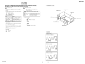
...solder It is shown on the lower right portion of the rear panel (see the illustration below). MODEL IDENTIFICATION - Parts No. Model US model Canadian model Part No. 2-661-458-0[] 2-661-458-1[] STR-K700 General Power requirements 120 V AC, 60 Hz Power consumption Area code US Canadian Power consumption 210 W 290 VA ... damaged by heat. Caution: The printed pattern (copper foil) may peel away if the heated tip is applied for example, "Models of the receiver you purchased is best to use caution not to let solder bridges occur such as on IC pins, etc. • Usable with the lead ...
...solder It is shown on the lower right portion of the rear panel (see the illustration below). MODEL IDENTIFICATION - Parts No. Model US model Canadian model Part No. 2-661-458-0[] 2-661-458-1[] STR-K700 General Power requirements 120 V AC, 60 Hz Power consumption Area code US Canadian Power consumption 210 W 290 VA ... damaged by heat. Caution: The printed pattern (copper foil) may peel away if the heated tip is applied for example, "Models of the receiver you purchased is best to use caution not to let solder bridges occur such as on IC pins, etc. • Usable with the lead ...
Service Manual
Page 3
... Board 24 3-14. Schematic Diagram - DIAGRAMS 3-1. MAIN Section 12 3-2. Printed Wiring Board - REPLACE THESE COMPONENTS WITH SONY PARTS WHOSE PART NUMBERS APPEAR AS SHOWN IN THIS MANUAL OR IN SUPPLEMENTS PUBLISHED BY SONY. DIGITAL Board (Side B) - ...... 15 3-5. STR-K700 SAFETY CHECK-OUT After correcting the original service problem, perform the following safety check before releasing the...
... Board 24 3-14. Schematic Diagram - DIAGRAMS 3-1. MAIN Section 12 3-2. Printed Wiring Board - REPLACE THESE COMPONENTS WITH SONY PARTS WHOSE PART NUMBERS APPEAR AS SHOWN IN THIS MANUAL OR IN SUPPLEMENTS PUBLISHED BY SONY. DIGITAL Board (Side B) - ...... 15 3-5. STR-K700 SAFETY CHECK-OUT After correcting the original service problem, perform the following safety check before releasing the...
Service Manual
Page 11
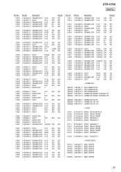
...FM • Voltages are dc with a VOM (Input impedance 10 MΩ). Parts on the pattern face side seen from the pattern face are taken with part number specified. DIGITAL Board - 1 IC1501 9 (MCLK1) 72 ns 1 V/DIV, 40 ns/DIV 2 IC1101 id (X1) 3.4 Vp-p 41.6 ns 1 V/DIV, 20 ns/DIV 3 IC1301 ws (XIN) 4.2 Vp-p STR-K700.... • All resistors are omitted. • Circuit Boards Location POWER board STANDBY board MAIN board STR-K700 ADCC board HEADPHONE board DISPLAY board DIGITAL board • Waveforms - Note: The components identified by mark 0 or dotted line ...
...FM • Voltages are dc with a VOM (Input impedance 10 MΩ). Parts on the pattern face side seen from the pattern face are taken with part number specified. DIGITAL Board - 1 IC1501 9 (MCLK1) 72 ns 1 V/DIV, 40 ns/DIV 2 IC1101 id (X1) 3.4 Vp-p 41.6 ns 1 V/DIV, 20 ns/DIV 3 IC1301 ws (XIN) 4.2 Vp-p STR-K700.... • All resistors are omitted. • Circuit Boards Location POWER board STANDBY board MAIN board STR-K700 ADCC board HEADPHONE board DISPLAY board DIGITAL board • Waveforms - Note: The components identified by mark 0 or dotted line ...

Service Manual
Page 34
...views are not supplied. • Items marked "*" are not stocked since they may have some difference from the original one. • The mechanical parts with RV102 1 3 4 #1 8 chassis section Ref. Description A-1156-368-A DISPLAY BOARD, COMPLETE 1-829-004-11 WIRE (FLAT TYPE) (19...5 3-087-053-01 +BVTP2.6 (3CR) Remark Ref. No. 6 7 8 9 Part No. STR-K700 SECTION 4 EXPLODED VIEWS NOTE: • -XX and -X mean standardized parts, so they are critical for routine service. No. 1 2 3 3 4 Part No. Replace only with mark 0 are seldom required for safety. FRONT PANEL SECTION The ...
...views are not supplied. • Items marked "*" are not stocked since they may have some difference from the original one. • The mechanical parts with RV102 1 3 4 #1 8 chassis section Ref. Description A-1156-368-A DISPLAY BOARD, COMPLETE 1-829-004-11 WIRE (FLAT TYPE) (19...5 3-087-053-01 +BVTP2.6 (3CR) Remark Ref. No. 6 7 8 9 Part No. STR-K700 SECTION 4 EXPLODED VIEWS NOTE: • -XX and -X mean standardized parts, so they are critical for routine service. No. 1 2 3 3 4 Part No. Replace only with mark 0 are seldom required for safety. FRONT PANEL SECTION The ...

Service Manual
Page 35
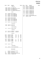
STR-K700 4-2. Description 3-701-748-00 CLAMP 4-249-675-01 +BV SUMITITE S 4X6 ROUND A-1156-365-A STANDBY BOARD, COMPLETE 3-077-331-21 +BV3 (3-CR) 3-905-609-01 ...-21 TUNER 7-685-646-79 SCREW +BVTP 3X8 TYPE2 IT-3 Remark 35 No. Q553 Q554 Q603 Q604 Q653 Q654 Q703 Q704 Q753 Q754 0 T901 TN1 #1 Part No. CHASSIS SECTION 51 52 54 not supplied #1 not supplied Q554 Q654 Q553 Q604 Q503 Q504 Q754 55 Q653 Q603 Q753 Q703 Q704 54 #1 54... TN1 #1 60 59 not supplied 61 #1 #1 61 not supplied Ref. No. 51 52 53 54 55 * 56 0 57 58 59 60 61 0 F901 Q503 Q504 Part No.
STR-K700 4-2. Description 3-701-748-00 CLAMP 4-249-675-01 +BV SUMITITE S 4X6 ROUND A-1156-365-A STANDBY BOARD, COMPLETE 3-077-331-21 +BV3 (3-CR) 3-905-609-01 ...-21 TUNER 7-685-646-79 SCREW +BVTP 3X8 TYPE2 IT-3 Remark 35 No. Q553 Q554 Q603 Q604 Q653 Q654 Q703 Q704 Q753 Q754 0 T901 TN1 #1 Part No. CHASSIS SECTION 51 52 54 not supplied #1 not supplied Q554 Q654 Q553 Q604 Q503 Q504 Q754 55 Q653 Q603 Q753 Q703 Q704 54 #1 54... TN1 #1 60 59 not supplied 61 #1 #1 61 not supplied Ref. No. 51 52 53 54 55 * 56 0 57 58 59 60 61 0 F901 Q503 Q504 Part No.
Service Manual
Page 36
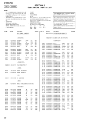
... Les composants identifiés par une marque 0 sont critiques pour la sécurité. STR-K700 ADCC DIGITAL SECTION 5 ELECTRICAL PARTS LIST NOTE: • Due to standardization, replacements in the parts list may be anticipated when ordering these items. • SEMICONDUCTORS In each case, u: µ...film resistor. uPA. . : µPA. . uPB. . : µPB. . uPD. . : µPD. . When indicating parts by mark 0 or dotted line with part number specified. Replace only with mark 0 are critical for example: uA. . : µA. . No. Description A-1156-372-A DIGITAL BOARD, ...
... Les composants identifiés par une marque 0 sont critiques pour la sécurité. STR-K700 ADCC DIGITAL SECTION 5 ELECTRICAL PARTS LIST NOTE: • Due to standardization, replacements in the parts list may be anticipated when ordering these items. • SEMICONDUCTORS In each case, u: µ...film resistor. uPA. . : µPA. . uPB. . : µPB. . uPD. . : µPD. . When indicating parts by mark 0 or dotted line with part number specified. Replace only with mark 0 are critical for example: uA. . : µA. . No. Description A-1156-372-A DIGITAL BOARD, ...
Service Manual
Page 37
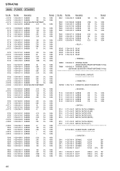
...-862-11 BEAD, FERRITE BEAD, FERRITE BEAD, FERRITE BEAD, FERRITE BEAD, FERRITE FB1405 1-400-862-11 BEAD, FERRITE 37 No. STR-K700 DIGITAL Ref. C1305 C1306 C1308 C1309 C1310 Part No. C1511 C1513 Part No. Description 1-100-566-91 CERAMIC CHIP 1-126-947-11 ELECT 1-100-566-91 CERAMIC CHIP 1-162-918-11 CERAMIC...
...-862-11 BEAD, FERRITE BEAD, FERRITE BEAD, FERRITE BEAD, FERRITE BEAD, FERRITE FB1405 1-400-862-11 BEAD, FERRITE 37 No. STR-K700 DIGITAL Ref. C1305 C1306 C1308 C1309 C1310 Part No. C1511 C1513 Part No. Description 1-100-566-91 CERAMIC CHIP 1-126-947-11 ELECT 1-100-566-91 CERAMIC CHIP 1-162-918-11 CERAMIC...
Service Manual
Page 40
... Remark Ref. No. STR-K700 DIGITAL DISPLAY HEADPHONE MAIN Ref. No. Part No. Description X1502 1-813-276-21 QUARTZ CRYSTAL (13.9MHz) R198 1-249-381-11 CARBON 1 R199 1-249-381-11 CARBON 1 Remark 5% 1/4W 5% 1/4W A-1156-368-A ...
... Remark Ref. No. STR-K700 DIGITAL DISPLAY HEADPHONE MAIN Ref. No. Part No. Description X1502 1-813-276-21 QUARTZ CRYSTAL (13.9MHz) R198 1-249-381-11 CARBON 1 R199 1-249-381-11 CARBON 1 Remark 5% 1/4W 5% 1/4W A-1156-368-A ...
Service Manual
Page 44
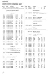
... 1/4W 1/4W 1/4W 1/4W 1/4W 1/4W 1/4W 1/4W 1/4W 1/4W 1/4W 1/4W 1/4W 1/6W 1/6W 1/4W 1/4W 1/4W 1/4W 1/4W 1/4W 1/4W 1/4W 1/4W Ref. Part No. No. Description Remark R857 1-249-429-11 CARBON 10K 5% 1/4W R862 R863 R864 R865 R882 1-247-895-00 1-249-429-11 1-247-871-91...-11 ELECT 1-126-943-11 ELECT 1-126-942-61 ELECT 3300uF 20% 16V 2200uF 20% 25V 1000uF 20% 25V 44 No. 0 R708 0 R709 0 R710 R711 Part No. STR-K700 MAIN POWER STANDBY Ref.
... 1/4W 1/4W 1/4W 1/4W 1/4W 1/4W 1/4W 1/4W 1/4W 1/4W 1/4W 1/4W 1/4W 1/6W 1/6W 1/4W 1/4W 1/4W 1/4W 1/4W 1/4W 1/4W 1/4W 1/4W Ref. Part No. No. Description Remark R857 1-249-429-11 CARBON 10K 5% 1/4W R862 R863 R864 R865 R882 1-247-895-00 1-249-429-11 1-247-871-91...-11 ELECT 1-126-943-11 ELECT 1-126-942-61 ELECT 3300uF 20% 16V 2200uF 20% 25V 1000uF 20% 25V 44 No. 0 R708 0 R709 0 R710 R711 Part No. STR-K700 MAIN POWER STANDBY Ref.
Service Manual
Page 45
... (DIA. 5) (4A/125V) 6-702-390-01 IC MN2488-OPY-MK Remark 45 Q504 Q553 Q554 Q603 Q604 Q653 Q654 Q703 Q704 Q753 Q754 0 T901 TN1 Part No. Description < CONNECTOR > Remark CNP801 1-784-922-11 PIN, CONNECTOR 5P CNP900 1-564-321-00 PIN, CONNECTOR (3.96mm PITCH) 2P CNP903 1-564-506-11 PLUG... 6-500-522-11 DIODE 10EDB40-TA2B5 6-500-522-11 DIODE 10EDB40-TA2B5 6-500-522-11 DIODE 10EDB40-TA2B5 6-500-522-11 DIODE 10EDB40-TA2B5 Ref. Part No. No. STR-K700 STANDBY Ref.
... (DIA. 5) (4A/125V) 6-702-390-01 IC MN2488-OPY-MK Remark 45 Q504 Q553 Q554 Q603 Q604 Q653 Q654 Q703 Q704 Q753 Q754 0 T901 TN1 Part No. Description < CONNECTOR > Remark CNP801 1-784-922-11 PIN, CONNECTOR 5P CNP900 1-564-321-00 PIN, CONNECTOR (3.96mm PITCH) 2P CNP903 1-564-506-11 PLUG... 6-500-522-11 DIODE 10EDB40-TA2B5 6-500-522-11 DIODE 10EDB40-TA2B5 6-500-522-11 DIODE 10EDB40-TA2B5 6-500-522-11 DIODE 10EDB40-TA2B5 Ref. Part No. No. STR-K700 STANDBY Ref.


