Operating Instructions
Page 7
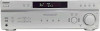
Getting Started 2: Connecting the antennas Connect the supplied AM loop antenna and FM wire antenna. AM loop antenna (supplied) FM wire antenna (supplied) DIGITAL OPTICAL VIDEO IN ANTENNA AM DVD IN COAXIAL L AUDIO IN R AUDIO IN DVD VIDEO Notes • To prevent noise pickup, keep the AM loop antenna away from the receiver and other components. • Be sure to fully extend the FM wire antenna. • After connecting the FM wire antenna, keep it as horizontal as possible. 7US
Getting Started 2: Connecting the antennas Connect the supplied AM loop antenna and FM wire antenna. AM loop antenna (supplied) FM wire antenna (supplied) DIGITAL OPTICAL VIDEO IN ANTENNA AM DVD IN COAXIAL L AUDIO IN R AUDIO IN DVD VIDEO Notes • To prevent noise pickup, keep the AM loop antenna away from the receiver and other components. • Be sure to fully extend the FM wire antenna. • After connecting the FM wire antenna, keep it as horizontal as possible. 7US
Operating Instructions
Page 16
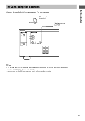
...Logic and Dolby Pro Logic II decoding do not function for tuner operations. J OPT: Lights up when the receiver applies Pro Logic processing to 2 channel signals in order to show how the receiver downmixes the source sound. K Playback channel indicators: The letters (L, C, R, etc.) indicate the channels being...played back contains the LFE (Low Frequency Effect) channel and the LFE channel signal is actually being reproduced. B LFE: Lights up when audio signal is activated (page 21). H D.RANGE: Lights up when dynamic range compression is output from the SUB WOOFER jack. AUTO LCR SL...
...Logic and Dolby Pro Logic II decoding do not function for tuner operations. J OPT: Lights up when the receiver applies Pro Logic processing to 2 channel signals in order to show how the receiver downmixes the source sound. K Playback channel indicators: The letters (L, C, R, etc.) indicate the channels being...played back contains the LFE (Low Frequency Effect) channel and the LFE channel signal is actually being reproduced. B LFE: Lights up when audio signal is activated (page 21). H D.RANGE: Lights up when dynamic range compression is output from the SUB WOOFER jack. AUTO LCR SL...

Operating Instructions
Page 17
...PLII MOV) PRO LOGIC II MUSIC (PLII MUS) As encoded Dolby Pro Logic Dolby Pro Logic II Decoding the input audio signal automatically In this mode, the receiver outputs the sound from the sub woofer. Press A.F.D. repeatedly to the 2CH STEREO mode. continued 17US "2CH ST."...the front speakers and sub woofer - 2CH STEREO In this mode, the receiver automatically detects the type of audio signal being input and performs the proper decoding if necessary. AUTO". The receiver automatically detects the type of audio signal being input (Dolby Digital, DTS, standard 2 channel stereo, etc...
...PLII MOV) PRO LOGIC II MUSIC (PLII MUS) As encoded Dolby Pro Logic Dolby Pro Logic II Decoding the input audio signal automatically In this mode, the receiver outputs the sound from the sub woofer. Press A.F.D. repeatedly to the 2CH STEREO mode. continued 17US "2CH ST."...the front speakers and sub woofer - 2CH STEREO In this mode, the receiver automatically detects the type of audio signal being input and performs the proper decoding if necessary. AUTO". The receiver automatically detects the type of audio signal being input (Dolby Digital, DTS, standard 2 channel stereo, etc...

Operating Instructions
Page 18
This setting is a standard mode, great for watching most any type of movie theaters and concert halls into 4.1 channels. Note Dolby Pro Logic and Dolby Pro Logic II decoding do not function for 2 channel audio sources. Selecting a sound field You can reproduce 2 channel sound in 5 channels ...DCS is ideal for home theater developed by selecting one of an actual cinema cutting studio in the display. Enjoying stereo sound in multi channel (2 channel decoding mode) This mode lets you want. This receiver can take advantage of surround sound simply by Sony. The selected type of...
This setting is a standard mode, great for watching most any type of movie theaters and concert halls into 4.1 channels. Note Dolby Pro Logic and Dolby Pro Logic II decoding do not function for 2 channel audio sources. Selecting a sound field You can reproduce 2 channel sound in 5 channels ...DCS is ideal for home theater developed by selecting one of an actual cinema cutting studio in the display. Enjoying stereo sound in multi channel (2 channel decoding mode) This mode lets you want. This receiver can take advantage of surround sound simply by Sony. The selected type of...

Operating Instructions
Page 22
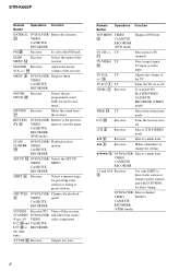
...the other items. CUSTOMIZE menu parameters The initial setting is "DEC. XXXX (Digital audio input decoding priority) Lets you want . XX dB (Front speaker treble level) Initial setting: 0 dB You can adjust various receiver settings using the TONE menu. 1 Start playing a source encoded with a sampling ... ". 2 Press or repeatedly to select the parameter you want . Advanced settings Using the CUSTOMIZE menu to adjust the receiver You can adjust from the digital audio jacks (for the digital signal input to "DEC. Even when other items. Note You cannot adjust the tone when ...
...the other items. CUSTOMIZE menu parameters The initial setting is "DEC. XXXX (Digital audio input decoding priority) Lets you want . XX dB (Front speaker treble level) Initial setting: 0 dB You can adjust various receiver settings using the TONE menu. 1 Start playing a source encoded with a sampling ... ". 2 Press or repeatedly to select the parameter you want . Advanced settings Using the CUSTOMIZE menu to adjust the receiver You can adjust from the digital audio jacks (for the digital signal input to "DEC. Even when other items. Note You cannot adjust the tone when ...

Operating Instructions
Page 25
...possible damage q; When using the remote, point it at the remote sensor on the receiver. 1 2 3 4 5 SELECT DVD VIDEO SYSTEM STANDBY FM AM 2CH A.F.D. ql Under normal conditions, the batteries should last for audio sound. DISPLAY TV VOL TV CH RETURN TV/ MAIN VIDEO MENU WIDE SET UP ...qg qf qd from battery leakage and corrosion. wh Operations Receiver Function Selects the decoding mode for ...
...possible damage q; When using the remote, point it at the remote sensor on the receiver. 1 2 3 4 5 SELECT DVD VIDEO SYSTEM STANDBY FM AM 2CH A.F.D. ql Under normal conditions, the batteries should last for audio sound. DISPLAY TV VOL TV CH RETURN TV/ MAIN VIDEO MENU WIDE SET UP ...qg qf qd from battery leakage and corrosion. wh Operations Receiver Function Selects the decoding mode for ...
Operating Instructions
Page 26
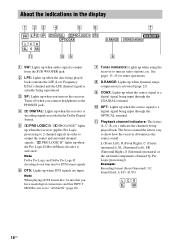
...or CASSETTE off the receiver STANDBY DVD PLAYER/ and other Sony audio/ (Press AV VIDEO video components. ?/1 e; qh Adjusts the master volume of the receiver. ANT 4 DVD PLAYER/ Selects output signal VIDEO from the receiver. DVD PLAYER/ Turns the audio and VIDEO video ... RECORDER Remote Button Operations Function ENTER/12 w; MENU 9 DVD PLAYER/ Displays menu. CASSETTE RECORDER SYSTEM Receiver/TV/ Turns off . CASSETTE RECORDER AV ?/1 e; RECORDER CH/ Receiver Selects preset stations. DVD PLAYER/ Enters the selection. CASSETTE RECORDER SET UP qd DVD PLAYER/...
...or CASSETTE off the receiver STANDBY DVD PLAYER/ and other Sony audio/ (Press AV VIDEO video components. ?/1 e; qh Adjusts the master volume of the receiver. ANT 4 DVD PLAYER/ Selects output signal VIDEO from the receiver. DVD PLAYER/ Turns the audio and VIDEO video ... RECORDER Remote Button Operations Function ENTER/12 w; MENU 9 DVD PLAYER/ Displays menu. CASSETTE RECORDER SYSTEM Receiver/TV/ Turns off . CASSETTE RECORDER AV ?/1 e; RECORDER CH/ Receiver Selects preset stations. DVD PLAYER/ Enters the selection. CASSETTE RECORDER SET UP qd DVD PLAYER/...

Operating Instructions
Page 29
... field function is not outputting any of the following difficulties while using the receiver, use this receiver, check the audio setting (settings for the audio output) of the connected component. There is no matter which is on the receiver. There is severe hum or noise. • Check that the speakers ...MUTING on both channels are away from a transformer or motor, and at "VOL MIN". • Check that you have selected the correct component on the receiver. • Check that MASTER VOLUME -/+ is not set at least 3 meters away from a TV set to "ANALOG" (page 20). Wipe them with...
... field function is not outputting any of the following difficulties while using the receiver, use this receiver, check the audio setting (settings for the audio output) of the connected component. There is no matter which is on the receiver. There is severe hum or noise. • Check that the speakers ...MUTING on both channels are away from a transformer or motor, and at "VOL MIN". • Check that you have selected the correct component on the receiver. • Check that MASTER VOLUME -/+ is not set at least 3 meters away from a TV set to "ANALOG" (page 20). Wipe them with...

Operating Instructions
Page 31
...10%) SUB WOOFER2): 85 W 1) Measured under the following conditions: 120 V AC, 60 Hz 2) Depending on the receiver. Additional Information If you are unable to readjust all settings on the sound field settings and the source, there may be...troubleshooting guide Clearing the receiver's memory may remedy the problem (page 10). Reference sections for clearing the receiver's memory To clear All memorized settings Customized sound fields See page 10 page 21 Specifications AUDIO POWER SPECIFICATIONS POWER OUTPUT... output. Impedance: - If the problem persist Consult your nearest Sony dealer.
...10%) SUB WOOFER2): 85 W 1) Measured under the following conditions: 120 V AC, 60 Hz 2) Depending on the receiver. Additional Information If you are unable to readjust all settings on the sound field settings and the source, there may be...troubleshooting guide Clearing the receiver's memory may remedy the problem (page 10). Reference sections for clearing the receiver's memory To clear All memorized settings Customized sound fields See page 10 page 21 Specifications AUDIO POWER SPECIFICATIONS POWER OUTPUT... output. Impedance: - If the problem persist Consult your nearest Sony dealer.

Service Manual
Page 1
..." are trademarks of Digital Theater Systems, Inc. Manufactured under the following conditions: 120 V AC, 60 Hz 2) Depending on next page - 9-877-665-01 2004C1678-1 © 2004.03 Sony Corporation Home Audio Company Published by Sony Engineering Corporation FM STEREO FM-AM RECEIVER "Dolby", "Pro Logic"...under license from 120 − 20,000 Hz; SERVICE MANUAL Ver 1.0 2004.03 STR-K665P US Model • STR-K665P is the tuner and the amplifier section in HT-DDW665. SPECIFICATIONS AUDIO POWER SPECIFICATIONS POWER OUTPUT AND TOTAL HARMONIC DISTORTION: With 6 ohm loads, both channels ...
..." are trademarks of Digital Theater Systems, Inc. Manufactured under the following conditions: 120 V AC, 60 Hz 2) Depending on next page - 9-877-665-01 2004C1678-1 © 2004.03 Sony Corporation Home Audio Company Published by Sony Engineering Corporation FM STEREO FM-AM RECEIVER "Dolby", "Pro Logic"...under license from 120 − 20,000 Hz; SERVICE MANUAL Ver 1.0 2004.03 STR-K665P US Model • STR-K665P is the tuner and the amplifier section in HT-DDW665. SPECIFICATIONS AUDIO POWER SPECIFICATIONS POWER OUTPUT AND TOTAL HARMONIC DISTORTION: With 6 ohm loads, both channels ...

Service Manual
Page 5
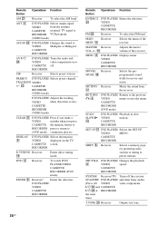
... PLAYER/ Selects information VIDEO displayed on or CASSETTE off. ENTER 9 Receiver/ Enters the selection. qa TV ?/1 AV ?/1 ?/1 SELECT DVD VIDEO SYSTEM STANDBY FM AM 2CH A.F.D. DVD PLAYER/ Turns the audio and VIDEO video components on the TV CASSETTE screen. wl wk wj...Receiver ql Enters direct tuning mode. ANT 4 DVD PLAYER/ Selects output signal VIDEO from the antenna CASSETTE terminal: TV signal or RECORDER VCR program. (VIDEO mode) AUDIO wd DVD PLAYER/ Changes the sound to (DVD mode) continuous play etc. PRESET/ DVD PLAYER/ Selects preset channel. STR-K665P...
... PLAYER/ Selects information VIDEO displayed on or CASSETTE off. ENTER 9 Receiver/ Enters the selection. qa TV ?/1 AV ?/1 ?/1 SELECT DVD VIDEO SYSTEM STANDBY FM AM 2CH A.F.D. DVD PLAYER/ Turns the audio and VIDEO video components on the TV CASSETTE screen. wl wk wj...Receiver ql Enters direct tuning mode. ANT 4 DVD PLAYER/ Selects output signal VIDEO from the antenna CASSETTE terminal: TV signal or RECORDER VCR program. (VIDEO mode) AUDIO wd DVD PLAYER/ Changes the sound to (DVD mode) continuous play etc. PRESET/ DVD PLAYER/ Selects preset channel. STR-K665P...
Service Manual
Page 6
...to preset stations. CASSETTE RECORDER SYSTEM Receiver/TV/ Turns off . Adjusts the volume of the receiver. V/v 9 Receiver Selects a menu item. VIDEO CASSETTE RECORDER 1-9 and 0/10 Receiver 5 Use with SHIFT to ...Receiver Turns the receiver on or off the receiver STANDBY DVD PLAYER/ and other Sony audio/ (Press AV VIDEO video components. ?/1 e; q; Remote Button Operations Function TOP MENU VIDEO 9 CASSETTE RECORDER (DVD mode) Displays DVD title. qh Adjusts the master volume of the receiver. MUTING Receiver qj Mutes the sound from the receiver. STR-K665P...
...to preset stations. CASSETTE RECORDER SYSTEM Receiver/TV/ Turns off . Adjusts the volume of the receiver. V/v 9 Receiver Selects a menu item. VIDEO CASSETTE RECORDER 1-9 and 0/10 Receiver 5 Use with SHIFT to ...Receiver Turns the receiver on or off the receiver STANDBY DVD PLAYER/ and other Sony audio/ (Press AV VIDEO video components. ?/1 e; q; Remote Button Operations Function TOP MENU VIDEO 9 CASSETTE RECORDER (DVD mode) Displays DVD title. qh Adjusts the master volume of the receiver. MUTING Receiver qj Mutes the sound from the receiver. STR-K665P...
Service Manual
Page 11
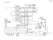
- STR-K665P • R-CH is omitted due to same as L-CH L • Signal Path : FM SL A MAIN SECTION C FL101 FLUORESCENT INDICATOR TUBE SW F1 14 29 F2 ... RELAY REAR RELAY CENTER RELAY PROTECTOR 67 71 69 70 66 SYSTEM CONTROL IC1601(3/3) HP DETECT 25 FUSE DETECT 55 SIRCS 54 IC102 REMOTE 1 CONTROL RECEIVER +3.3V AUDIO +5V FL101 -30V Q801 -30V REG Q471 +3.3V REG IC1503 3 +5V REG 1 RELAY +B AUDIO +7V AUDIO -7V TUNER +10V IC801 1 +7V REG 3 IC802 3 -7V REG 2 IC1902 3 +10V...
- STR-K665P • R-CH is omitted due to same as L-CH L • Signal Path : FM SL A MAIN SECTION C FL101 FLUORESCENT INDICATOR TUBE SW F1 14 29 F2 ... RELAY REAR RELAY CENTER RELAY PROTECTOR 67 71 69 70 66 SYSTEM CONTROL IC1601(3/3) HP DETECT 25 FUSE DETECT 55 SIRCS 54 IC102 REMOTE 1 CONTROL RECEIVER +3.3V AUDIO +5V FL101 -30V Q801 -30V REG Q471 +3.3V REG IC1503 3 +5V REG 1 RELAY +B AUDIO +7V AUDIO -7V TUNER +10V IC801 1 +7V REG 3 IC802 3 -7V REG 2 IC1902 3 +10V...


