
Limited Warranty (U.S. Only)
Page 1
...DAMAGES FOR BREACH OF ANY EXPRESS OR IMPLIED WARRANTY ON THIS PRODUCT. In addition, if you enter into a service contract with the Sony Partnership within the Warranty period must pay for all accessories are for all labor charges. 2. has established telephone numbers for product information ... the date of protection, to service the Product. 4-557-173-02 General Stereo/Hifi Components/Tape Decks ® CD Players/Mini Disc Players/Audio Systems Hifi Audio LIMITED WARRANTY Sony Electronics Inc. ("Sony") warrants this Product is invalid if the factory applied serial number has been ...
...DAMAGES FOR BREACH OF ANY EXPRESS OR IMPLIED WARRANTY ON THIS PRODUCT. In addition, if you enter into a service contract with the Sony Partnership within the Warranty period must pay for all accessories are for all labor charges. 2. has established telephone numbers for product information ... the date of protection, to service the Product. 4-557-173-02 General Stereo/Hifi Components/Tape Decks ® CD Players/Mini Disc Players/Audio Systems Hifi Audio LIMITED WARRANTY Sony Electronics Inc. ("Sony") warrants this Product is invalid if the factory applied serial number has been ...
Operating Instructions (HT-DDW650)
Page 1
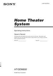
HT-DDW650 © 2003 Sony Corporation 4-244-183-71(1) Home Theater System Operating Instructions Owner's Record The model and serial numbers are located at the rear of the unit. Record the serial number in the space provided below. Serial No. Refer to them whenever you call upon your Sony dealer regarding this product. Model No.
HT-DDW650 © 2003 Sony Corporation 4-244-183-71(1) Home Theater System Operating Instructions Owner's Record The model and serial numbers are located at the rear of the unit. Record the serial number in the space provided below. Serial No. Refer to them whenever you call upon your Sony dealer regarding this product. Model No.
Operating Instructions (HT-DDW650)
Page 2
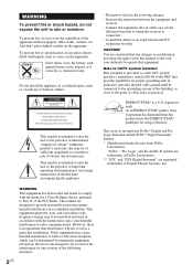
.... WARNING This equipment has been tested and found to provide reasonable protection against harmful interference in a residential installation. Reorient or relocate the receiving antenna. - "Dolby", "Pro Logic" and the double-D symbol are trademarks of Dolby Laboratories. ** "DTS" and "DTS Digital ...instructions, may be of sufficient magnitude to constitute a risk of electric shock to which the receiver is connected. - As an ENERGY STAR® partner, Sony Corporation has determined that may cause harmful interference to correct the interference by turning the equipment...
.... WARNING This equipment has been tested and found to provide reasonable protection against harmful interference in a residential installation. Reorient or relocate the receiving antenna. - "Dolby", "Pro Logic" and the double-D symbol are trademarks of Dolby Laboratories. ** "DTS" and "DTS Digital ...instructions, may be of sufficient magnitude to constitute a risk of electric shock to which the receiver is connected. - As an ENERGY STAR® partner, Sony Corporation has determined that may cause harmful interference to correct the interference by turning the equipment...
Operating Instructions (HT-DDW650)
Page 3
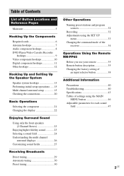
...display 22 Enjoying Surround Sound Using only the front speakers (2 Channel Stereo 23 Enjoying higher fidelity sound 23 Selecting a sound field 24 Understanding the multi channel surround displays 26 Customizing sound fields 27 Receiving Broadcasts Direct tuning 29 Automatic tuning 30 Preset tuning 30 Other Operations...Naming preset stations and program sources 32 Recording 32 Adjustments using the SET UP menu 33 Changing the command mode of the receiver 34 Operations Using the Remote RM-PP65 Before you use your remote 35 Remote button description 35 Changing the factory setting ...
...display 22 Enjoying Surround Sound Using only the front speakers (2 Channel Stereo 23 Enjoying higher fidelity sound 23 Selecting a sound field 24 Understanding the multi channel surround displays 26 Customizing sound fields 27 Receiving Broadcasts Direct tuning 29 Automatic tuning 30 Preset tuning 30 Other Operations...Naming preset stations and program sources 32 Recording 32 Adjustments using the SET UP menu 33 Changing the command mode of the receiver 34 Operations Using the Remote RM-PP65 Before you use your remote 35 Remote button description 35 Changing the factory setting ...
Operating Instructions (HT-DDW650)
Page 4
Receiver STR-K650P - Note for the supplied remote For RM-PP65 The >10/11 and 12 buttons on the use the controls on the supplied remote if they have the same or similar names as those on the receiver. For details on the remote are not available. 4US About This Manual The HT-DDW650 consists of your remote, see pages 35 - 39. You can also use of : - Speaker system • Front/surround speakers SS-MSP75 • Center speaker SS-CNP75 • Sub woofer SA-WMSP85 Tip The instructions in this manual describe the controls on the receiver.
Receiver STR-K650P - Note for the supplied remote For RM-PP65 The >10/11 and 12 buttons on the use the controls on the supplied remote if they have the same or similar names as those on the receiver. For details on the remote are not available. 4US About This Manual The HT-DDW650 consists of your remote, see pages 35 - 39. You can also use of : - Speaker system • Front/surround speakers SS-MSP75 • Center speaker SS-CNP75 • Sub woofer SA-WMSP85 Tip The instructions in this manual describe the controls on the receiver.
Operating Instructions (HT-DDW650)
Page 5
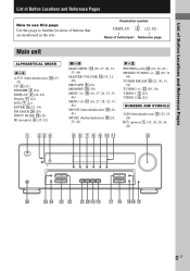
...are mentioned in the text. L A.F.D. (button/indicator) w; (23- 25) CD 9 (21) DIMMER 3 (22) DISPLAY 2 (22, 42) Display qa (22) DVD 7 (21) ENTER qg (32, 34) FM MODE wf (29) INPUT MODE qd (21) IR (receptor) 4 (35, 42) 1 23 4 M - wd (29, 30) VIDEO 1 5 (21) VIDEO 2 6 (21) NUMBERS AND SYMBOLS 2CH (button/...indicator) wa (23, 25, 28) `/1 (power) 1 (15, 20, 28, 34, 44) qs ?/1 g wh wg wf wd ws wa w; ws (30, 31, 44) TUNER FM/AM q; (21, 30, 31, 32) TUNING +/- Z PHONES (jack) wh (21, 26, 41) PRESET TUNING +/- List of Button Locations and Reference Pages List of Button Locations...
...are mentioned in the text. L A.F.D. (button/indicator) w; (23- 25) CD 9 (21) DIMMER 3 (22) DISPLAY 2 (22, 42) Display qa (22) DVD 7 (21) ENTER qg (32, 34) FM MODE wf (29) INPUT MODE qd (21) IR (receptor) 4 (35, 42) 1 23 4 M - wd (29, 30) VIDEO 1 5 (21) VIDEO 2 6 (21) NUMBERS AND SYMBOLS 2CH (button/...indicator) wa (23, 25, 28) `/1 (power) 1 (15, 20, 28, 34, 44) qs ?/1 g wh wg wf wd ws wa w; ws (30, 31, 44) TUNER FM/AM q; (21, 30, 31, 32) TUNING +/- Z PHONES (jack) wh (21, 26, 41) PRESET TUNING +/- List of Button Locations and Reference Pages List of Button Locations...
Operating Instructions (HT-DDW650)
Page 6
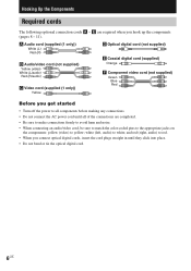
white (left, audio) to yellow; A Audio cord (supplied (1 only)) White (L) Red (R) B Audio/video cord (not supplied) Yellow (video) White (L/audio) Red (R/audio) C Video cord (supplied (1 only)) Yellow D Optical digital cord (not supplied) E Coaxial digital cord (supplied) Orange F Component video cord (not supplied) Green Blue Red Before you get started • Turn off the power to all components before making any connections. • Do not connect the AC power cord until all of the connections are required when you connect optical digital cords, insert the cord plugs straight in ...
white (left, audio) to yellow; A Audio cord (supplied (1 only)) White (L) Red (R) B Audio/video cord (not supplied) Yellow (video) White (L/audio) Red (R/audio) C Video cord (supplied (1 only)) Yellow D Optical digital cord (not supplied) E Coaxial digital cord (supplied) Orange F Component video cord (not supplied) Green Blue Red Before you get started • Turn off the power to all components before making any connections. • Do not connect the AC power cord until all of the connections are required when you connect optical digital cords, insert the cord plugs straight in ...
Operating Instructions (HT-DDW650)
Page 7
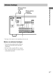
Hooking Up the Components Antenna hookups AM loop antenna (supplied) FM wire antenna (supplied) DIGITAL OPTICAL VIDEO 2 IN DVD IN COAXIAL ANTENNA AM y FM 75Ω COAXIAL MONITOR VIDEO IN VIDEO IN VIDEO OUT VIDEO IN VIDEO OUT L AUDIO OUT R IN CD OUT IN AUDIO IN AUDIO IN ... connector varies depending on antenna hookups • To prevent noise pickup, keep the AM loop antenna away from the receiver and other components. • Be sure to fully extend the FM wire antenna. • After connecting the FM wire antenna, keep it as horizontal as possible. 7US Notes on the area code.
Hooking Up the Components Antenna hookups AM loop antenna (supplied) FM wire antenna (supplied) DIGITAL OPTICAL VIDEO 2 IN DVD IN COAXIAL ANTENNA AM y FM 75Ω COAXIAL MONITOR VIDEO IN VIDEO IN VIDEO OUT VIDEO IN VIDEO OUT L AUDIO OUT R IN CD OUT IN AUDIO IN AUDIO IN ... connector varies depending on antenna hookups • To prevent noise pickup, keep the AM loop antenna away from the receiver and other components. • Be sure to fully extend the FM wire antenna. • After connecting the FM wire antenna, keep it as horizontal as possible. 7US Notes on the area code.
Operating Instructions (HT-DDW650)
Page 8
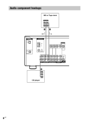
Audio component hookups DIGITAL OPTICAL VIDEO 2 IN DVD IN COAXIAL MD or Tape deck INPUT OUTPUT LINE LINE L R A A OUT IN ç ç ANTENNA AM y FM 75Ω COAXIAL MONITOR VIDEO IN VIDEO IN VIDEO OUT VIDEO IN VIDEO OUT L AUDIO OUT R IN CD OUT IN AUDIO IN AUDIO IN AUDIO OUT AUDIO IN SUB MD/TAPE DVD VIDEO 2 VIDEO 1 WOOFER A OUTPUT LINE L R CD player 8US
Audio component hookups DIGITAL OPTICAL VIDEO 2 IN DVD IN COAXIAL MD or Tape deck INPUT OUTPUT LINE LINE L R A A OUT IN ç ç ANTENNA AM y FM 75Ω COAXIAL MONITOR VIDEO IN VIDEO IN VIDEO OUT VIDEO IN VIDEO OUT L AUDIO OUT R IN CD OUT IN AUDIO IN AUDIO IN AUDIO OUT AUDIO IN SUB MD/TAPE DVD VIDEO 2 VIDEO 1 WOOFER A OUTPUT LINE L R CD player 8US
Operating Instructions (HT-DDW650)
Page 9
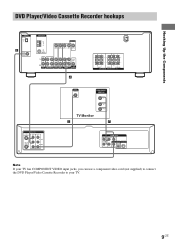
Hooking Up the Components DVD Player/Video Cassette Recorder hookups DIGITAL OPTICAL VIDEO 2 IN E DVD IN COAXIAL ANTENNA AM y FM 75Ω COAXIAL MONITOR VIDEO IN VIDEO IN VIDEO OUT VIDEO IN VIDEO OUT L AUDIO OUT R IN CD OUT IN AUDIO IN AUDIO IN AUDIO ...
Hooking Up the Components DVD Player/Video Cassette Recorder hookups DIGITAL OPTICAL VIDEO 2 IN E DVD IN COAXIAL ANTENNA AM y FM 75Ω COAXIAL MONITOR VIDEO IN VIDEO IN VIDEO OUT VIDEO IN VIDEO OUT L AUDIO OUT R IN CD OUT IN AUDIO IN AUDIO IN AUDIO ...
Operating Instructions (HT-DDW650)
Page 10
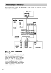
... tuner, connect both the audio and video output jacks to the VIDEO 2 AUDIO IN jacks on the receiver. DVD player OUTPUT AUDIO OUT R L VIDEO OUT B DIGITAL OPTICAL VIDEO 2 IN DVD IN COAXIAL ANTENNA AM y FM 75Ω COAXIAL MONITOR VIDEO IN VIDEO IN VIDEO OUT VIDEO IN VIDEO OUT L AUDIO OUT R...VIDEO VIDEO IN OUT AUDIO AUDIO IN OUT L R VCR Note on video component hookups You can hookup your TV's audio output jacks to the receiver as shown below. C INPUT VIDEO IN TV monitor 10US Video component hookups If you can connect your video components as shown above.
... tuner, connect both the audio and video output jacks to the VIDEO 2 AUDIO IN jacks on the receiver. DVD player OUTPUT AUDIO OUT R L VIDEO OUT B DIGITAL OPTICAL VIDEO 2 IN DVD IN COAXIAL ANTENNA AM y FM 75Ω COAXIAL MONITOR VIDEO IN VIDEO IN VIDEO OUT VIDEO IN VIDEO OUT L AUDIO OUT R...VIDEO VIDEO IN OUT AUDIO AUDIO IN OUT L R VCR Note on video component hookups You can hookup your TV's audio output jacks to the receiver as shown below. C INPUT VIDEO IN TV monitor 10US Video component hookups If you can connect your video components as shown above.
Operating Instructions (HT-DDW650)
Page 11
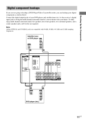
.... Satellite tuner or DVD player OUTPUT VIDEO OUT OUTPUT DIGITAL OPTICAL AUDIO OUT L R D B DIGITAL OPTICAL VIDEO 2 IN DVD IN COAXIAL ANTENNA AM y FM 75Ω COAXIAL MONITOR VIDEO IN VIDEO IN VIDEO OUT VIDEO IN VIDEO OUT L AUDIO OUT R IN CD OUT IN AUDIO IN AUDIO IN AUDIO...OUTPUT VIDEO OUT AUDIO OUT L R DVD player (etc.) 11US Connect the digital output jacks of your DVD player and satellite tuner (etc.) to the receiver's digital input jacks to hookup a DVD Player/Video Cassette Recorder, you are not going to bring the multi channel surround sound of a movie theater into...
.... Satellite tuner or DVD player OUTPUT VIDEO OUT OUTPUT DIGITAL OPTICAL AUDIO OUT L R D B DIGITAL OPTICAL VIDEO 2 IN DVD IN COAXIAL ANTENNA AM y FM 75Ω COAXIAL MONITOR VIDEO IN VIDEO IN VIDEO OUT VIDEO IN VIDEO OUT L AUDIO OUT R IN CD OUT IN AUDIO IN AUDIO IN AUDIO...OUTPUT VIDEO OUT AUDIO OUT L R DVD player (etc.) 11US Connect the digital output jacks of your DVD player and satellite tuner (etc.) to the receiver's digital input jacks to hookup a DVD Player/Video Cassette Recorder, you are not going to bring the multi channel surround sound of a movie theater into...
Operating Instructions (HT-DDW650)
Page 12
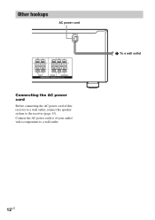
Other hookups AC power cord RL RL RL RL FRONT CENTER SURROUND SPEAKERS IMPEDANCE USE 8 - 16Ω Connecting the AC power cord Before connecting the AC power cord of your audio/ video components to the receiver (page 13). b To a wall outlet 12US Connect the AC power cord(s) of this receiver to a wall outlet, connect the speaker system to a wall outlet.
Other hookups AC power cord RL RL RL RL FRONT CENTER SURROUND SPEAKERS IMPEDANCE USE 8 - 16Ω Connecting the AC power cord Before connecting the AC power cord of your audio/ video components to the receiver (page 13). b To a wall outlet 12US Connect the AC power cord(s) of this receiver to a wall outlet, connect the speaker system to a wall outlet.
Operating Instructions (HT-DDW650)
Page 13
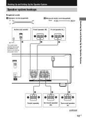
Hooking Up and Setting Up the Speaker System Hooking Up and Setting Up the Speaker System Speaker system hookups Required cords A Speaker cords (supplied) (+) (-) B Monaural audio cord (supplied) Black Active sub woofer INPUT AUDIO IN Front speaker (R) Front speaker (L) e Ee E b B To a wall outlet (Switch the power (POWER) to off before connecting the power cord.) A A MONITOR VIDEO OUT AUDIO OUT SUB WOOFER RL RL RL RL FRONT CENTER SURROUND SPEAKERS IMPEDANCE USE 8 - 16Ω E A A A e Ee Ee Center speaker Surround speaker Surround speaker (R) (L) continued ...
Hooking Up and Setting Up the Speaker System Hooking Up and Setting Up the Speaker System Speaker system hookups Required cords A Speaker cords (supplied) (+) (-) B Monaural audio cord (supplied) Black Active sub woofer INPUT AUDIO IN Front speaker (R) Front speaker (L) e Ee E b B To a wall outlet (Switch the power (POWER) to off before connecting the power cord.) A A MONITOR VIDEO OUT AUDIO OUT SUB WOOFER RL RL RL RL FRONT CENTER SURROUND SPEAKERS IMPEDANCE USE 8 - 16Ω E A A A e Ee Ee Center speaker Surround speaker Surround speaker (R) (L) continued ...
Operating Instructions (HT-DDW650)
Page 14
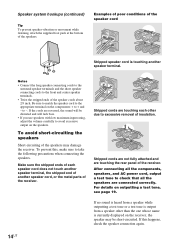
...the components: + to the appropriate terminal on outputting a test tone, see page 19. Stripped cords are touching the rear panel of the receiver. Stripped cords are not fully attached and are touching each speaker cord does not touch another speaker terminal, the stripped end of another speaker ...while listening, attach the supplied foot pads at the bottom of the speaker cords about 2/3 inch. Examples of poor conditions of the receiver. to excessive removal of the speakers may be distorted and will be short-circuited. If the cords are connected correctly. To avoid short...
...the components: + to the appropriate terminal on outputting a test tone, see page 19. Stripped cords are touching the rear panel of the receiver. Stripped cords are not fully attached and are touching each speaker cord does not touch another speaker terminal, the stripped end of another speaker ...while listening, attach the supplied foot pads at the bottom of the speaker cords about 2/3 inch. Examples of poor conditions of the receiver. to excessive removal of the speakers may be distorted and will be short-circuited. If the cords are connected correctly. To avoid short...
Operating Instructions (HT-DDW650)
Page 15
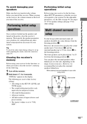
... using your side (long room) B A A 45° Sub woofer C C 90° 20° continued 15US However, we recommend that the receiver correspond to "VOL MIN". "INITIAL" appears in the SET UP, LEVEL and TONE menus. • The sound field memorized for each input selector and ... 5 seconds. Performing initial setup operations Once you have hooked up the speakers and turned on page 46. The following . 1 Turn off the receiver. Tip To check the audio output during settings (to set to your system. You can be the same distance from the listening position (A). When...
... using your side (long room) B A A 45° Sub woofer C C 90° 20° continued 15US However, we recommend that the receiver correspond to "VOL MIN". "INITIAL" appears in the SET UP, LEVEL and TONE menus. • The sound field memorized for each input selector and ... 5 seconds. Performing initial setup operations Once you have hooked up the speakers and turned on page 46. The following . 1 Turn off the receiver. Tip To check the audio output during settings (to set to your system. You can be the same distance from the listening position (A). When...
Operating Instructions (HT-DDW650)
Page 16
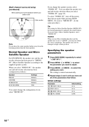
....", do the same procedure.) Tip The setting for Micro Satellite Speaker (MICRO SP.) has been programmed to the supplied speaker system. Caution When you use Sony's Micro Satellite Speakers, select "MICRO SP.". to select the setting you want . Initial settings Parameter L R DIST. XX ft. SP.". XX ft. SL SR DIST. SL...
....", do the same procedure.) Tip The setting for Micro Satellite Speaker (MICRO SP.) has been programmed to the supplied speaker system. Caution When you use Sony's Micro Satellite Speakers, select "MICRO SP.". to select the setting you want . Initial settings Parameter L R DIST. XX ft. SP.". XX ft. SL SR DIST. SL...
Operating Instructions (HT-DDW650)
Page 17
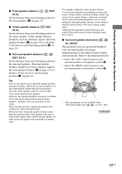
... speaker distance ( L R DIST. And they can not be set the center speaker further than the front speakers. x Surround speaker placement ( SL SR PL. Tip The receiver allows you specify the height of distance. In other words, the speaker will cause a delay in much better surround sound. XXXX)* This parameter lets you...
... speaker distance ( L R DIST. And they can not be set the center speaker further than the front speakers. x Surround speaker placement ( SL SR PL. Tip The receiver allows you specify the height of distance. In other words, the speaker will cause a delay in much better surround sound. XXXX)* This parameter lets you...
Operating Instructions (HT-DDW650)
Page 18
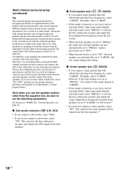
All modes with virtual elements will not be sure to set to "LARGE") or sub woofer.*1 • If you playback multi channel surround encoded software and listen to the effect each listening environment has many variables, like wall reflections. Nevertheless, each setting has on "NORM. Therefore, we recommend that you do not connect a sub woofer, select "NO". XXX) • If you connect a sub woofer, select "YES". • If you connect a large speaker that will effectively reproduce bass frequencies, select "LARGE". This activates the bass redirection circuitry and outputs the...
All modes with virtual elements will not be sure to set to "LARGE") or sub woofer.*1 • If you playback multi channel surround encoded software and listen to the effect each listening environment has many variables, like wall reflections. Nevertheless, each setting has on "NORM. Therefore, we recommend that you do not connect a sub woofer, select "NO". XXX) • If you connect a sub woofer, select "YES". • If you connect a large speaker that will effectively reproduce bass frequencies, select "LARGE". This activates the bass redirection circuitry and outputs the...
Operating Instructions (HT-DDW650)
Page 19
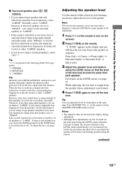
... described above and adjust the speaker levels from each speaker. Press MASTER VOL +/- on the remote or turn on the receiver. 2 Press T.TONE on the receiver. However, if the front speakers are shown in the TONE menu to output the bass frequencies from that channel. Adjusting ...using the LEVEL menu (when the test tone is performed. 4 Press T.TONE again to the following Dolby Pro Logic modes *1 NORMAL *2 PHANTOM *3 3 STEREO Tip Internally, the LARGE and SMALL settings for easier speaker level adjustment. 1 Press ?/1 on the remote to "LARGE". For details on the LEVEL menu,...
... described above and adjust the speaker levels from each speaker. Press MASTER VOL +/- on the remote or turn on the receiver. 2 Press T.TONE on the receiver. However, if the front speakers are shown in the TONE menu to output the bass frequencies from that channel. Adjusting ...using the LEVEL menu (when the test tone is performed. 4 Press T.TONE again to the following Dolby Pro Logic modes *1 NORMAL *2 PHANTOM *3 3 STEREO Tip Internally, the LARGE and SMALL settings for easier speaker level adjustment. 1 Press ?/1 on the remote to "LARGE". For details on the LEVEL menu,...