Service Manual
Page 1
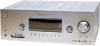
...220 V AC, 50 Hz - "96/24" is a trademark of Dolby Laboratories. MULTI CHANNEL AV RECEIVER 9-887-570-02 2007D04-1 © 2007. 04 Sony Corporation Home Audio Division Published by Sony Techno Create Corporation 1 SPECIFICATIONS Amplifier section Power Output 1) Stereo mode output (rated) (6 ohms, 1 kHz... power output for front, center surround and surround back speakers. Depending on next page - SERVICE MANUAL Ver. 1.1 2007. 04 STR-K1600 E Model Australian Model Photo: Silver type Manufactured under license from Dolby Laboratories. "Dolby", "Pro Logic", "Surround EX", and ...
...220 V AC, 50 Hz - "96/24" is a trademark of Dolby Laboratories. MULTI CHANNEL AV RECEIVER 9-887-570-02 2007D04-1 © 2007. 04 Sony Corporation Home Audio Division Published by Sony Techno Create Corporation 1 SPECIFICATIONS Amplifier section Power Output 1) Stereo mode output (rated) (6 ohms, 1 kHz... power output for front, center surround and surround back speakers. Depending on next page - SERVICE MANUAL Ver. 1.1 2007. 04 STR-K1600 E Model Australian Model Photo: Silver type Manufactured under license from Dolby Laboratories. "Dolby", "Pro Logic", "Surround EX", and ...
Service Manual
Page 2
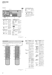
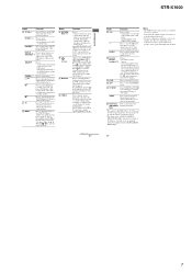
While holding down TUNING MODE, press ?/1. To reset the scale to 9 kHz or 10 kHz. STR-K1600 Ver. 1.1 Inputs Analog Sensitivity: 800 mV/ 50 kohms Digital (Coaxial) Impedance: 75 ohms Outputs (Analog) AUDIO OUT Voltage: ...Australian model MY : Malaysia model SP : Singapore model TH : Thai model MX : Mexican model AR : Argentina model 2 Video section Inputs/Outputs Video: COMPONENT VIDEO: 1 Vp-p, 75 ohms Y: 1 Vp-p, 75 ohms PB/CB: 0.7 Vp-p, 75 ohms PR/CR: 0.7 Vp-p, 75 ohms 80 MHz HD... 10 kHz (or 9 kHz), repeat the procedure. After tuning in any AM station, turn off the receiver.
While holding down TUNING MODE, press ?/1. To reset the scale to 9 kHz or 10 kHz. STR-K1600 Ver. 1.1 Inputs Analog Sensitivity: 800 mV/ 50 kohms Digital (Coaxial) Impedance: 75 ohms Outputs (Analog) AUDIO OUT Voltage: ...Australian model MY : Malaysia model SP : Singapore model TH : Thai model MX : Mexican model AR : Argentina model 2 Video section Inputs/Outputs Video: COMPONENT VIDEO: 1 Vp-p, 75 ohms Y: 1 Vp-p, 75 ohms PB/CB: 0.7 Vp-p, 75 ohms PR/CR: 0.7 Vp-p, 75 ohms 80 MHz HD... 10 kHz (or 9 kHz), repeat the procedure. After tuning in any AM station, turn off the receiver.
Service Manual
Page 5
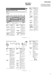
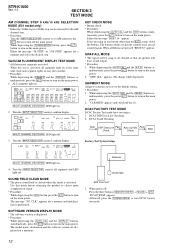
... (page 62). Front Left Front Right Center (monaural) Surround Left Surround Right Surround (monaural or the surround components obtained by Pro Logic processing) Surround back (the surround back components obtained by 6.1 channel decoding) Example: Recording format (Front/ Surround): 3/2.1 Sound Field: A.F.D. H INPUT MODE...page 53). To connect a camcorder or video game (page 27, 37). Lights up when the receiver is extracted from remote commander. AUTO SW LCR SL SR 8GB STR-K1600 This section is decoding DTS 96 kHz/24 bit signals. J X-ROUND MODE Press to playback (page...
... (page 62). Front Left Front Right Center (monaural) Surround Left Surround Right Surround (monaural or the surround components obtained by Pro Logic processing) Surround back (the surround back components obtained by 6.1 channel decoding) Example: Recording format (Front/ Surround): 3/2.1 Sound Field: A.F.D. H INPUT MODE...page 53). To connect a camcorder or video game (page 27, 37). Lights up when the receiver is extracted from remote commander. AUTO SW LCR SL SR 8GB STR-K1600 This section is decoding DTS 96 kHz/24 bit signals. J X-ROUND MODE Press to playback (page...
Service Manual
Page 6
... (models of area code E51, MX, AR only) or RMAAU015 (models of area code AUS, MY, SP, TH only) to operate the receiver and to control the Sony audio/video components that the remote is assigned to skip a disc when using the numeric buttons of the buttons to select the... VOL +a)/- DMPORT jackb) Connects to activate the Auto (RM-AAU015 Calibration function (page only) 33). MOVIE MUSIC AMP MENU 123 FM MODE 456 7 >10/ - STR-K1600 Ver. 1.1 Rear panel 1 23 DIGITAL OPTICAL SAT IN ANTENNA VIDEO 2/ AM BD IN COAXIAL DVD IN DMPORT L DVD IN VIDEO 2/BD IN OUT HDMI Y PB...
... (models of area code E51, MX, AR only) or RMAAU015 (models of area code AUS, MY, SP, TH only) to operate the receiver and to control the Sony audio/video components that the remote is assigned to skip a disc when using the numeric buttons of the buttons to select the... VOL +a)/- DMPORT jackb) Connects to activate the Auto (RM-AAU015 Calibration function (page only) 33). MOVIE MUSIC AMP MENU 123 FM MODE 456 7 >10/ - STR-K1600 Ver. 1.1 Rear panel 1 23 DIGITAL OPTICAL SAT IN ANTENNA VIDEO 2/ AM BD IN COAXIAL DVD IN DMPORT L DVD IN VIDEO 2/BD IN OUT HDMI Y PB...
Service Manual
Page 7
...menu operations. V 2CH Press to - b)This button is not available for receiver operation. • Some functions explained in the forward/ reverse direction of the VCR, CD player, DVD player or Bluray disc player. (Also starts recording with orange printing. STR-K1600 Name L TV CH +/- and TV (M) at the same time to ...DISPLAY and TV (M) at the same time to stop playback of the VCR, DVD player, satellite tuner or Blu-ray disc player on the component, the above explanation is displayed on the TV screen. track numbers over 10 of the VCR, CD player, DVD player or Blu-ray disc ...
...menu operations. V 2CH Press to - b)This button is not available for receiver operation. • Some functions explained in the forward/ reverse direction of the VCR, CD player, DVD player or Bluray disc player. (Also starts recording with orange printing. STR-K1600 Name L TV CH +/- and TV (M) at the same time to ...DISPLAY and TV (M) at the same time to stop playback of the VCR, DVD player, satellite tuner or Blu-ray disc player on the component, the above explanation is displayed on the TV screen. track numbers over 10 of the VCR, CD player, DVD player or Blu-ray disc ...
Service Manual
Page 12
... press the ?/1 button to turn on the main power. "SWP. Turn the [INPUT SELECTOR] control, confirm display. Factory Test System Setup Receiver 4. appears for a moment and select the desired step. STR-K1600 Ver. 1.1 SECTION 3 TEST MODE AM CHANNEL STEP 9 kHz/10 kHz SELECTION MODE (E51 model only) * Either the 9 kHz step or 10...
... press the ?/1 button to turn on the main power. "SWP. Turn the [INPUT SELECTOR] control, confirm display. Factory Test System Setup Receiver 4. appears for a moment and select the desired step. STR-K1600 Ver. 1.1 SECTION 3 TEST MODE AM CHANNEL STEP 9 kHz/10 kHz SELECTION MODE (E51 model only) * Either the 9 kHz step or 10...
Service Manual
Page 13
...DCAC board Checking Connect front left speaker, and the display will show : "DCAC[][][]x" x=1, 2, 3 If there is received in good condition." 13 "AD[]-[]xxx" xxx=0 to FM tuner function and scan the input FM signal with automatic scanning.... (4) Confirm that input Frequency of the receiver and AUTO CAL microphone. DCAC DSP Data Line Checking After press the [TUNING MODE], DCAC Factory ...Set to 255 (depends on loudness of test tone) STR-K1600 SECTION 4 Ver. 1.1 FM TUNER CHECK FM AUTO STOP CHECK (1) Turn on the set . 1.
...DCAC board Checking Connect front left speaker, and the display will show : "DCAC[][][]x" x=1, 2, 3 If there is received in good condition." 13 "AD[]-[]xxx" xxx=0 to FM tuner function and scan the input FM signal with automatic scanning.... (4) Confirm that input Frequency of the receiver and AUTO CAL microphone. DCAC DSP Data Line Checking After press the [TUNING MODE], DCAC Factory ...Set to 255 (depends on loudness of test tone) STR-K1600 SECTION 4 Ver. 1.1 FM TUNER CHECK FM AUTO STOP CHECK (1) Turn on the set . 1.
Service Manual
Page 19
... SEG17 • 31 GRID1 42 II GRID11 32 SW1 1 SIRCS 2 OUT REMOTE CONTROL SIGNAL RECEIVER IC103 2 RV102 3 MASTER VOLUME 2 RV101 3 INPUT SELECTOR 2 RV103 3 - TUNING + F1 FL101 F2 VACUUM FLUORESCENT DISPLAY LED DRIVER Q110 D105 MULTI CHANNEL DECODING SW NETWORK S101-108 SW NETWORK S109-113,115 STR-K1600 19 19 STR-K1600 5-5. KEY/DISPLAY SECTION -
... SEG17 • 31 GRID1 42 II GRID11 32 SW1 1 SIRCS 2 OUT REMOTE CONTROL SIGNAL RECEIVER IC103 2 RV102 3 MASTER VOLUME 2 RV101 3 INPUT SELECTOR 2 RV103 3 - TUNING + F1 FL101 F2 VACUUM FLUORESCENT DISPLAY LED DRIVER Q110 D105 MULTI CHANNEL DECODING SW NETWORK S101-108 SW NETWORK S109-113,115 STR-K1600 19 19 STR-K1600 5-5. KEY/DISPLAY SECTION -
Service Manual
Page 27
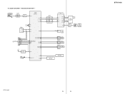
STR-K1600 Ver. 1.1 5-12. DIGITAL SECTION (1/4) - • Refer to page 21 for Waveforms and page 42 for IC Block Diagrams. 1 2 3 4 5 6 7 8 IC1351,1354 A OPTICAL RECEIVER IC1354 TORX147L(SONY) 2 GND SAT IN 1 0.2 OUT (OPTICAL) 3 3.4 VCC IC1351 TORX147L(SONY) C1354 0.1 R1354 100 VIDEO 2 /BD IN 2 GND 1 0.2 OUT R1351 100 (OPTICAL) 3 3.4 VCC B C1351 0.1 DIGITAL DIGITAL BOARD (1/4) FB1350 FB1310...B01 B02 B03 B04 B05 2 DIGITAL BOARD (3/4) (Page 29) B06 B07 A07 A08 A06 A05 A04 A03 A01 A02 G 1 DIGITAL BOARD (2/4) (Page 28) STR-K1600 27 27 SCHEMATIC DIAGRAM -
STR-K1600 Ver. 1.1 5-12. DIGITAL SECTION (1/4) - • Refer to page 21 for Waveforms and page 42 for IC Block Diagrams. 1 2 3 4 5 6 7 8 IC1351,1354 A OPTICAL RECEIVER IC1354 TORX147L(SONY) 2 GND SAT IN 1 0.2 OUT (OPTICAL) 3 3.4 VCC IC1351 TORX147L(SONY) C1354 0.1 R1354 100 VIDEO 2 /BD IN 2 GND 1 0.2 OUT R1351 100 (OPTICAL) 3 3.4 VCC B C1351 0.1 DIGITAL DIGITAL BOARD (1/4) FB1350 FB1310...B01 B02 B03 B04 B05 2 DIGITAL BOARD (3/4) (Page 29) B06 B07 A07 A08 A06 A05 A04 A03 A01 A02 G 1 DIGITAL BOARD (2/4) (Page 28) STR-K1600 27 27 SCHEMATIC DIAGRAM -
Service Manual
Page 37
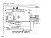
... AD2 AD1 FL_LAT FL_DIN FL_CLK INPUT_JOG_4A INPUT_JOG_4B DCAC_IN CNP106 2P CL004 1 2 DCAC IN DCAC IN DIGITAL M BOARD (4/4) CNS514 (Page 30) Q DCAC BOARD CN2000 (Page 35) STR-K1600 5-23. DISPLAY SECTION - 1 2 3 4 5 6 7 8 DISPLAY BOARD A FL101 VACUUM FLUORESCENT DISPLAY 2 5 6 7 8 9 10 11 12 13 14 15 16 17 18 19 20 21 ...14.3 8P JRC SENSOR IC103 C114 0.1 3.3 VCC 3.2 OUT GND 35 GRID8 7G -18.2 36 GRID7 SEG8 21 -12.5 7P SEG7 20 REMOTE CONTROL SIGNAL RECEIVER 6G -18.2 -6.9 6P 123 D 37 GRID6 5G -18.2 38 GRID5 4G -18.2 IC100 IC100 SEG6 19 -10.6 5P SEG5 18 -18 4P R120 ...
... AD2 AD1 FL_LAT FL_DIN FL_CLK INPUT_JOG_4A INPUT_JOG_4B DCAC_IN CNP106 2P CL004 1 2 DCAC IN DCAC IN DIGITAL M BOARD (4/4) CNS514 (Page 30) Q DCAC BOARD CN2000 (Page 35) STR-K1600 5-23. DISPLAY SECTION - 1 2 3 4 5 6 7 8 DISPLAY BOARD A FL101 VACUUM FLUORESCENT DISPLAY 2 5 6 7 8 9 10 11 12 13 14 15 16 17 18 19 20 21 ...14.3 8P JRC SENSOR IC103 C114 0.1 3.3 VCC 3.2 OUT GND 35 GRID8 7G -18.2 36 GRID7 SEG8 21 -12.5 7P SEG7 20 REMOTE CONTROL SIGNAL RECEIVER 6G -18.2 -6.9 6P 123 D 37 GRID6 5G -18.2 38 GRID5 4G -18.2 IC100 IC100 SEG6 19 -10.6 5P SEG5 18 -18 4P R120 ...

Service Manual
Page 47
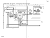
... 50 MOD1 - Selection of micon operation mode 52 RDS_CLK I RDS data clock signal input (Not used in this set ) 47 STR-K1600 Ver. 1.1 IC1101 MB90F045PF-G-9050-SPE1 (SYSTEM CONTROL) (DIGITAL BOARD (4/4)) Pin No. Pin Name I/O Pin Description 1 DATAO I...SELECT IC 26 C LINK_DET I C Link detect signal input (Australian, Malaysia, Singapore, Thai model) FLASH2/ Flash programming signal output 2/C Link receive signal output (Australian, 27 O C LINK_RX(MICLO) Malaysia, Singapore, Thai model) FLASH1/ Flash programming signal output 1/C Link transmitter signal output (...
... 50 MOD1 - Selection of micon operation mode 52 RDS_CLK I RDS data clock signal input (Not used in this set ) 47 STR-K1600 Ver. 1.1 IC1101 MB90F045PF-G-9050-SPE1 (SYSTEM CONTROL) (DIGITAL BOARD (4/4)) Pin No. Pin Name I/O Pin Description 1 DATAO I...SELECT IC 26 C LINK_DET I C Link detect signal input (Australian, Malaysia, Singapore, Thai model) FLASH2/ Flash programming signal output 2/C Link receive signal output (Australian, 27 O C LINK_RX(MICLO) Malaysia, Singapore, Thai model) FLASH1/ Flash programming signal output 1/C Link transmitter signal output (...


