
Service Manual
Page 2
...code Any differences in operation, according to 10 kHz (or 9 kHz), repeat the procedure. To reset the scale to the area code, are subject to 9 kHz or 10 kHz. All preset stations... for example, "Models of area code AA only". 2 Video section Inputs/Outputs Video: 1 Vp-p, 75 ohms COMPONENT VIDEO: Y: 1 Vp-p, 75 ohms PB/CB/B-Y: 0.7 Vp-p, 75 ohms PR/CR/R-Y: 0.7 Vp-p, 75 ohms...Mass (Approx.) 8.0 kg Design and specifications are clearly indicated in any AM station, turn off the receiver. STR-K1500 Ver. 1.1 AM tuner section Tuning range Models of area code SP, SP6, AUS With 9-kHz...
...code Any differences in operation, according to 10 kHz (or 9 kHz), repeat the procedure. To reset the scale to the area code, are subject to 9 kHz or 10 kHz. All preset stations... for example, "Models of area code AA only". 2 Video section Inputs/Outputs Video: 1 Vp-p, 75 ohms COMPONENT VIDEO: Y: 1 Vp-p, 75 ohms PB/CB/B-Y: 0.7 Vp-p, 75 ohms PR/CR/R-Y: 0.7 Vp-p, 75 ohms...Mass (Approx.) 8.0 kg Design and specifications are clearly indicated in any AM station, turn off the receiver. STR-K1500 Ver. 1.1 AM tuner section Tuning range Models of area code SP, SP6, AUS With 9-kHz...

Service Manual
Page 12
...button to turn on the main power. 2. "CLEARED" appears and switch off . 6. While depressing the TUNING MODE and the A.F.D. " PROT. STR-K1500 SECTION 2 TEST MODE FACTORY PRESET MODE All preset contents are not counted again. 3. Procedure: 1. Turn off the main power. 2. While depressing... DISPLAY MODE The software version is activated, all buttons are pressed "REST 00" appears. The buttons which are already counted once are reset to clients upon completion of repair. PROTECTOR Procedure: 1. EVER" appears. (3 second) DECODE AUTO ALL Procedure: 1. Select the desired step...
...button to turn on the main power. 2. "CLEARED" appears and switch off . 6. While depressing the TUNING MODE and the A.F.D. " PROT. STR-K1500 SECTION 2 TEST MODE FACTORY PRESET MODE All preset contents are not counted again. 3. Procedure: 1. Turn off the main power. 2. While depressing... DISPLAY MODE The software version is activated, all buttons are pressed "REST 00" appears. The buttons which are already counted once are reset to clients upon completion of repair. PROTECTOR Procedure: 1. EVER" appears. (3 second) DECODE AUTO ALL Procedure: 1. Select the desired step...

Service Manual
Page 17
... 789 B MAIN SECTION (Page 16) FL_DATA FL_CLK IC101 BUFFER 9 -V OUT1 3 Q110 LED DRIVE D105 Q534 BOOSTER FL_LAT SYSTEM CONTROL IC1101(2/2) X0 X1 A/D1 A/D2 ADCC STR-K1500 J2000 AUTO CAL MIC 82 83 39 40 38 X1101 24MHz FUNCTION KEY S108-111,115 FUNCTION KEY S101-107 IC2000 5 AMP 1 VOL_ENC(B) VOL_ENC(A) ENC_B... 66 69 68 67 56 58 S100 ?/1 FUSE DETECT 63 SIRCS 54 AVCC 35 VCC3 84 VCC5 23 RSTX 77 STOP 48 IC102 REMOTE 1 CONTROL RECEIVER IC1111 1 RESET 2 +3.3V +2.5V +5V TUNER +10V RELAY +B AUDIO +7V AUDIO +5V AUDIO -7V +3.3V (STBY) 17 17 Q801 -20V REG D802 R803 T901 Q691,...
... 789 B MAIN SECTION (Page 16) FL_DATA FL_CLK IC101 BUFFER 9 -V OUT1 3 Q110 LED DRIVE D105 Q534 BOOSTER FL_LAT SYSTEM CONTROL IC1101(2/2) X0 X1 A/D1 A/D2 ADCC STR-K1500 J2000 AUTO CAL MIC 82 83 39 40 38 X1101 24MHz FUNCTION KEY S108-111,115 FUNCTION KEY S101-107 IC2000 5 AMP 1 VOL_ENC(B) VOL_ENC(A) ENC_B... 66 69 68 67 56 58 S100 ?/1 FUSE DETECT 63 SIRCS 54 AVCC 35 VCC3 84 VCC5 23 RSTX 77 STOP 48 IC102 REMOTE 1 CONTROL RECEIVER IC1111 1 RESET 2 +3.3V +2.5V +5V TUNER +10V RELAY +B AUDIO +7V AUDIO +5V AUDIO -7V +3.3V (STBY) 17 17 Q801 -20V REG D802 R803 T901 Q691,...
Service Manual
Page 44
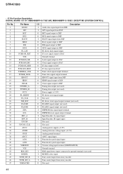
Power supply (+3.3V) O FL driver reset signal output O Not used - Not used - Analog power supply (+3.3V) I Version setting input terminal (DESTINATION) - Analog ground terminal I ADCC signal input I Function key push signal ... output to DSP O PM signal output to DSP O GP12 signal output to DSP O FL driver latch signal output O IC reset signal output to DAC - STR-K1500 • IC Pin Function Description DIGITAL BOARD IC1101 MB90488BPF-G-175E1:MX, MB90488BPF-G-193E1: EXCEPT MX (SYSTEM CONTROL) Pin No. 1 2 3 4 5 6 7 8 9 10 11 12 13 14 15 ...
Power supply (+3.3V) O FL driver reset signal output O Not used - Not used - Analog power supply (+3.3V) I Version setting input terminal (DESTINATION) - Analog ground terminal I ADCC signal input I Function key push signal ... output to DSP O PM signal output to DSP O GP12 signal output to DSP O FL driver latch signal output O IC reset signal output to DAC - STR-K1500 • IC Pin Function Description DIGITAL BOARD IC1101 MB90488BPF-G-175E1:MX, MB90488BPF-G-193E1: EXCEPT MX (SYSTEM CONTROL) Pin No. 1 2 3 4 5 6 7 8 9 10 11 12 13 14 15 ...

Service Manual
Page 45
... - Not used - Connection for a crystal resonator - Not used - Not used O BST signal output terminal O Reset signal output to DIR O CKSEL control signal output to DIR O Clock signal output to DIR O Chip enable signal output to DIR STR-K1500 45 Ground terminal - Ground terminal - Pin No. 48 49 50 51 52 53 54 55...
... - Not used - Connection for a crystal resonator - Not used - Not used O BST signal output terminal O Reset signal output to DIR O CKSEL control signal output to DIR O Clock signal output to DIR O Chip enable signal output to DIR STR-K1500 45 Ground terminal - Ground terminal - Pin No. 48 49 50 51 52 53 54 55...


