
Limited Warranty (U.S. Only)
Page 1
...OF ANY EXPRESS OR IMPLIED WARRANTY ON THIS PRODUCT. 4-557-173-02 General Stereo/Hifi Components/Tape Decks ® CD Players/Mini Disc Players/Audio Systems Hifi Audio LIMITED WARRANTY Sony Electronics Inc. ("Sony") warrants this Product is within 90 days of the date of the Product,...WARRANTY OF MERCHANTABILITY OR FITNESS FOR A PARTICULAR PURPOSE ON THIS PRODUCT IS LIMITED IN DURATION TO THE DURATION OF THIS WARRANTY. PARTS: In addition, Sony will repair or replace the Product, at its original packaging or packaging affording an equal degree of incidental or consequential damages, or...
...OF ANY EXPRESS OR IMPLIED WARRANTY ON THIS PRODUCT. 4-557-173-02 General Stereo/Hifi Components/Tape Decks ® CD Players/Mini Disc Players/Audio Systems Hifi Audio LIMITED WARRANTY Sony Electronics Inc. ("Sony") warrants this Product is within 90 days of the date of the Product,...WARRANTY OF MERCHANTABILITY OR FITNESS FOR A PARTICULAR PURPOSE ON THIS PRODUCT IS LIMITED IN DURATION TO THE DURATION OF THIS WARRANTY. PARTS: In addition, Sony will repair or replace the Product, at its original packaging or packaging affording an equal degree of incidental or consequential damages, or...
Operating Instructions (Receiver)
Page 2
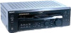
...numbers are not going to use any further. STR-DE545/DE445/SE501 Serial No. On placement • Place the receiver in a location with adequate ventilation to prevent heat buildup and prolong the life of the receiver. • Do not place the receiver near heat sources, or in this manual ... consult your Sony dealer regarding this equipment. This symbol is identical with the limits for proper grounding and, in the literature accompanying the appliance. INFORMATION This equipment has been tested and found to Part 15 of cable entry as it any type of safety and will not...
...numbers are not going to use any further. STR-DE545/DE445/SE501 Serial No. On placement • Place the receiver in a location with adequate ventilation to prevent heat buildup and prolong the life of the receiver. • Do not place the receiver near heat sources, or in this manual ... consult your Sony dealer regarding this equipment. This symbol is identical with the limits for proper grounding and, in the literature accompanying the appliance. INFORMATION This equipment has been tested and found to Part 15 of cable entry as it any type of safety and will not...
Operating Instructions (Receiver)
Page 3
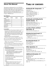
... names as those on the use of Parts and Basic Operations 22 Front Panel Parts Descriptions 22 Enjoying Surround Sound 27 Selecting a Sound Field 28 Understanding the Multi-Channel Surround Displays 31 Customizing Sound Fields 33 Receiving Broadcasts 37 Direct Tuning 39 Automatic Tuning ...sound when the demonstration mode is used for the STR-DE545, STR-DE445 and STR-SE501. When the demonstration starts, the following icon is activated. In this manual: z Indicates hints and tips for making the task easier. This receiver incorporates Dolby* Digital and Pro Logic Surround and the...
... names as those on the use of Parts and Basic Operations 22 Front Panel Parts Descriptions 22 Enjoying Surround Sound 27 Selecting a Sound Field 28 Understanding the Multi-Channel Surround Displays 31 Customizing Sound Fields 33 Receiving Broadcasts 37 Direct Tuning 39 Automatic Tuning ...sound when the demonstration mode is used for the STR-DE545, STR-DE445 and STR-SE501. When the demonstration starts, the following icon is activated. In this manual: z Indicates hints and tips for making the task easier. This receiver incorporates Dolby* Digital and Pro Logic Surround and the...
Operating Instructions (Receiver)
Page 22
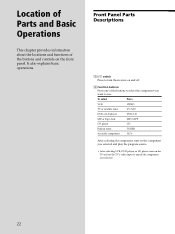
... CD player CD Built in tuner TUNER An audio component AUX After selecting the component, turn on the component you selected. 22 Location of Parts and Basic Operations This chapter provides information about the locations and functions of the buttons to select the component you want to match the component... you selected and play the program source. • After selecting VCR, DVD player, or LD player, turn the receiver on and off. 2 Function buttons Press one of the buttons and controls on the TV and set the TV's video input to use. It also...
... CD player CD Built in tuner TUNER An audio component AUX After selecting the component, turn on the component you selected. 22 Location of Parts and Basic Operations This chapter provides information about the locations and functions of the buttons to select the component you want to match the component... you selected and play the program source. • After selecting VCR, DVD player, or LD player, turn the receiver on and off. 2 Function buttons Press one of the buttons and controls on the TV and set the TV's video input to use. It also...
Operating Instructions (Receiver)
Page 23
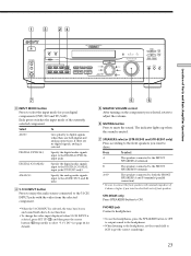
...of the currently selected component. D. 2CH MODE I - TUNING + SHIFT - TUNING + MEMORY FM/AM FM MODE MUTING BASS BOOST TONE Location of 8 ohms or higher if you want to mute the sound...; To change the video input displayed when 5.1CH INPUT is muted. 7 SPEAKERS selector (STR-DE545 and STR-SE501 only) Press according to the front speakers you selected, rotate to adjust the volume...button Press to enjoy the audio source connected to the 5.1CH INPUT jacks with nominal impedance of Parts and Basic Amplifier Operations 7 3 INPUT MODE button Press to select the input mode for details...
...of the currently selected component. D. 2CH MODE I - TUNING + SHIFT - TUNING + MEMORY FM/AM FM MODE MUTING BASS BOOST TONE Location of 8 ohms or higher if you want to mute the sound...; To change the video input displayed when 5.1CH INPUT is muted. 7 SPEAKERS selector (STR-DE545 and STR-SE501 only) Press according to the front speakers you selected, rotate to adjust the volume...button Press to enjoy the audio source connected to the 5.1CH INPUT jacks with nominal impedance of Parts and Basic Amplifier Operations 7 3 INPUT MODE button Press to select the input mode for details...

Operating Instructions (Receiver)
Page 24
TUNING + SHIFT - TUNING + MEMORY FM/AM FM MODE BASS MUTING BOOST TONE Location of Parts and Basic Amplifier Operations !£ !¢ 8 DISPLAY button Press repeatedly to change the information on . 24 A.F.D. button / indicator Press to set the receiver to automatically detect the type of ...button. ** Frequency appears only when the tuner is the same as follows: v Index name of the front speakers. D. 2CH MODE I - Front Panel Parts Description 98 !™ !¡ @º !§ !∞ ? / 1 SPEAKERS R ON r OFF A B PHONES MULTI CHANNEL DECODING DIMMER DISPLAY ...
TUNING + SHIFT - TUNING + MEMORY FM/AM FM MODE BASS MUTING BOOST TONE Location of Parts and Basic Amplifier Operations !£ !¢ 8 DISPLAY button Press repeatedly to change the information on . 24 A.F.D. button / indicator Press to set the receiver to automatically detect the type of ...button. ** Frequency appears only when the tuner is the same as follows: v Index name of the front speakers. D. 2CH MODE I - Front Panel Parts Description 98 !™ !¡ @º !§ !∞ ? / 1 SPEAKERS R ON r OFF A B PHONES MULTI CHANNEL DECODING DIMMER DISPLAY ...
Operating Instructions (Receiver)
Page 25
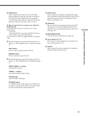
... to activate the surround parameters (page 33). Note that is improved. For details, see "Receiving Broadcasts" starting from page 37. qk SUR button Press to activate the speaker level parameters (...etc.). SHIFT button Selects a memory page for preset stations. FM MODE button If "STEREO" flashes in the display and the FM stereo reception is turned on the tone effect. wa Jog dial ...operate the built-in tuner. FM/AM button Selects the FM or AM band. qg The following buttons operate the built-in tuner. Location of Parts and Basic Amplifier Operations qf TONE...
... to activate the surround parameters (page 33). Note that is improved. For details, see "Receiving Broadcasts" starting from page 37. qk SUR button Press to activate the speaker level parameters (...etc.). SHIFT button Selects a memory page for preset stations. FM MODE button If "STEREO" flashes in the display and the FM stereo reception is turned on the tone effect. wa Jog dial ...operate the built-in tuner. FM/AM button Selects the FM or AM band. qg The following buttons operate the built-in tuner. Location of Parts and Basic Amplifier Operations qf TONE...

Operating Instructions (Receiver)
Page 26
... front, center, rear speaker sizes, the rear speaker position, and whether or not you are using the jog dial (wa). Location of Parts and Basic Amplifier Operations Front Panel Parts Description ws SET UP button Press to activate the setup mode, then use the cursor buttons (w;) to enter individual characters for preset...
... front, center, rear speaker sizes, the rear speaker position, and whether or not you are using the jog dial (wa). Location of Parts and Basic Amplifier Operations Front Panel Parts Description ws SET UP button Press to activate the setup mode, then use the cursor buttons (w;) to enter individual characters for preset...
Operating Instructions (Receiver)
Page 48
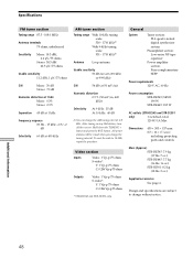
...S-video*: Y: 1 Vp-p 75 ohms C: 0.286 Vp-p 75 ohms * STR-DE545 and STR-SE501 only. After tuning in .) including projecting parts and controls Mass (Approx.) STR-DE545: 7.9 kg (17 lbs. 7 oz.) STR-DE445: 7.7 kg (16 lbs. 16 oz.) STR-SE501: 8.2 kg (18 lbs. 2 oz.) Supplied accessories See page 4. ...STR-DE545/SE501: 190 W STR-DE445: 185 W AC outlets (STR-DE545 and STR-SE501 only) 1 switched, total 120 W/1A Max Dimensions 430 × 303 × 157 mm (17 × 12 × 61/4 in any AM station, turn off the receiver. Design and specifications are subject to 9 kHz. Specifications FM...
...S-video*: Y: 1 Vp-p 75 ohms C: 0.286 Vp-p 75 ohms * STR-DE545 and STR-SE501 only. After tuning in .) including projecting parts and controls Mass (Approx.) STR-DE545: 7.9 kg (17 lbs. 7 oz.) STR-DE445: 7.7 kg (16 lbs. 16 oz.) STR-SE501: 8.2 kg (18 lbs. 2 oz.) Supplied accessories See page 4. ...STR-DE545/SE501: 190 W STR-DE445: 185 W AC outlets (STR-DE545 and STR-SE501 only) 1 switched, total 120 W/1A Max Dimensions 430 × 303 × 157 mm (17 × 12 × 61/4 in any AM station, turn off the receiver. Design and specifications are subject to 9 kHz. Specifications FM...


