Service Manual
Page 3
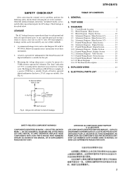
... chassis, must have a 2V AC range are examples of a passive VOM that have an accurate low-voltage scale. Printed Wiring Board Main Section 14 3-8. STR-DE475 SAFETY CHECK-OUT After correcting the original service problem, perform the following safety checks before releasing the set to the customer:...OR DOTTED LINE WITH MARK 0 ON THE SCHEMATIC DIAGRAMS AND IN THE PARTS LIST ARE CRITICAL TO SAFE OPERATION. REPLACE THESE COMPONENTS WITH SONY PARTS WHOSE PART NUMBERS APPEAR AS SHOWN IN THIS MANUAL OR IN SUPPLEMENTS PUBLISHED BY SONY. ATTENTION AU COMPOSANT AYANT RAPPORT À LA ...
... chassis, must have a 2V AC range are examples of a passive VOM that have an accurate low-voltage scale. Printed Wiring Board Main Section 14 3-8. STR-DE475 SAFETY CHECK-OUT After correcting the original service problem, perform the following safety checks before releasing the set to the customer:...OR DOTTED LINE WITH MARK 0 ON THE SCHEMATIC DIAGRAMS AND IN THE PARTS LIST ARE CRITICAL TO SAFE OPERATION. REPLACE THESE COMPONENTS WITH SONY PARTS WHOSE PART NUMBERS APPEAR AS SHOWN IN THIS MANUAL OR IN SUPPLEMENTS PUBLISHED BY SONY. ATTENTION AU COMPOSANT AYANT RAPPORT À LA ...
Service Manual
Page 7
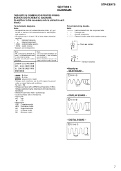
SECTION 3 DIAGRAMS STR-DE475 THIS NOTE IS COMMON FOR PRINTED WIRING BOARDS AND SCHEMATIC DIAGRAMS. (In addition to this necessary note is printed in each block.) For schematic diagrams. Note: • All capacitors are omitted. Line. • H : adjustment for repair. • Voltages ... pour la sécurité. AR : Argentine model. MX : Mexican model. • Waveform - or dotted line with part number specified. No mark : FM • Voltages are critical for electrolytics and tantalums. • All resistors are omitted. • A : B+ Line. • B : B- CH : ...
SECTION 3 DIAGRAMS STR-DE475 THIS NOTE IS COMMON FOR PRINTED WIRING BOARDS AND SCHEMATIC DIAGRAMS. (In addition to this necessary note is printed in each block.) For schematic diagrams. Note: • All capacitors are omitted. Line. • H : adjustment for repair. • Voltages ... pour la sécurité. AR : Argentine model. MX : Mexican model. • Waveform - or dotted line with part number specified. No mark : FM • Voltages are critical for electrolytics and tantalums. • All resistors are omitted. • A : B+ Line. • B : B- CH : ...
Service Manual
Page 14
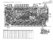
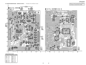
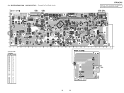
STR-DE475 There are a few cases that the part printed on this diagram isn't mounted in this model. Location Ref. No. Location Ref. Location Ref. No. Location Ref. TUNER UNIT IC 301 IC 404 IC 402 IC 403 ... IC 501 IC 701 IC 401 IC 803 IC 801 IC 802 IC 702 (Page 18) (Page 16) • Semiconductor Location Ref. No. No. PRINTED WIRING BOARD - No. No. Location Ref. No. MAIN SECTION - • See page 8 for Circuit Boards Location. Location Ref. Location Ref. No. 3-7. Location D505 F-4 D506 F-4 D508 F-3 D510...
STR-DE475 There are a few cases that the part printed on this diagram isn't mounted in this model. Location Ref. No. Location Ref. Location Ref. No. Location Ref. TUNER UNIT IC 301 IC 404 IC 402 IC 403 ... IC 501 IC 701 IC 401 IC 803 IC 801 IC 802 IC 702 (Page 18) (Page 16) • Semiconductor Location Ref. No. No. PRINTED WIRING BOARD - No. No. Location Ref. No. MAIN SECTION - • See page 8 for Circuit Boards Location. Location Ref. Location Ref. No. 3-7. Location D505 F-4 D506 F-4 D508 F-3 D510...
Service Manual
Page 16
...18) IC 1002 IC 1010 IC 1009 IC 1013 (Page 14) IC 1003 STR-DE475 There are a few cases that the part printed on this diagram isn't mounted in this model. No. Location D1101 C-7 D1201 D-3 D1202 ...D-3 D1301 B-3 IC1002 A-2 IC1003 B-5 IC1004 B-7 IC1005 B-8 IC1006 C-7 IC1007 E-7 IC1008 D-6 IC1009 C-3 IC1010 B-3 IC1011 E-1 IC1013 B-3 IC1201 E-6 IC1251 E-5 (Page 14) IC 1008 IC 1251 IC 1201 IC 1007 16 16 Location Ref. DIGITAL SECTION - • See page 8 for Circuit Boards Location. PRINTED WIRING...
...18) IC 1002 IC 1010 IC 1009 IC 1013 (Page 14) IC 1003 STR-DE475 There are a few cases that the part printed on this diagram isn't mounted in this model. No. Location D1101 C-7 D1201 D-3 D1202 ...D-3 D1301 B-3 IC1002 A-2 IC1003 B-5 IC1004 B-7 IC1005 B-8 IC1006 C-7 IC1007 E-7 IC1008 D-6 IC1009 C-3 IC1010 B-3 IC1011 E-1 IC1013 B-3 IC1201 E-6 IC1251 E-5 (Page 14) IC 1008 IC 1251 IC 1201 IC 1007 16 16 Location Ref. DIGITAL SECTION - • See page 8 for Circuit Boards Location. PRINTED WIRING...
Service Manual
Page 18
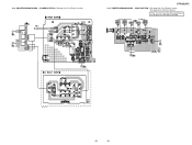
... B-13 IC102 B-7 IC103 B-10 Q008 D-12 Q009 C-5 Q100 A-8 Q101 A-7 Q103 D-3 Q104 D-3 18 18 STR-DE475 There are a few cases that the part printed on this diagram isn't mounted in this model. (Page 20) (Page 14) IC 101 (Page 14) PRINTED WIRING BOARD - DISPLAY SECTION - • See page 8 for Circuit Boards Location. (Page 16) (Page...
... B-13 IC102 B-7 IC103 B-10 Q008 D-12 Q009 C-5 Q100 A-8 Q101 A-7 Q103 D-3 Q104 D-3 18 18 STR-DE475 There are a few cases that the part printed on this diagram isn't mounted in this model. (Page 20) (Page 14) IC 101 (Page 14) PRINTED WIRING BOARD - DISPLAY SECTION - • See page 8 for Circuit Boards Location. (Page 16) (Page...
Service Manual
Page 20
PRINTED WIRING BOARD - 3-13. There are a few cases that the part printed on this diagram isn't mounted in this model. POWER SECTION -• See page 8 for Schematic Diagram. VIDEO SECTION -• See page 8 for Circuit Boards Location. • See page 20 for Circuit Boards Location. (Page 14) (Page 14) IC 950 (Page 18) STR-DE475 3-14. PRINTED WIRING BOARD - IC 1015 IC 1014 (Page 18) (Page 14) E model only 1-680-431- 20 20
PRINTED WIRING BOARD - 3-13. There are a few cases that the part printed on this diagram isn't mounted in this model. POWER SECTION -• See page 8 for Schematic Diagram. VIDEO SECTION -• See page 8 for Circuit Boards Location. • See page 20 for Circuit Boards Location. (Page 14) (Page 14) IC 950 (Page 18) STR-DE475 3-14. PRINTED WIRING BOARD - IC 1015 IC 1014 (Page 18) (Page 14) E model only 1-680-431- 20 20


