Sony HCD-SH2000 Support Question
Sony HCD-SH2000 Support Question
Find answers below for this question about Sony HCD-SH2000.Need a Sony HCD-SH2000 manual? We have 1 online manual for this item!
Question posted by Fontelle42 on October 8th, 2023
Wires And Adapters
how can I get the wires and adapters that goes from the speakers to the receiver on my hcd sh2000 stereo syste
Current Answers
Answer #1: Posted by SonuKumar on October 8th, 2023 10:41 PM
SonuKumar

Member since:
May 9th, 2021 Points: 16,604,810

Member since:
May 9th, 2021 Points: 16,604,810
Please respond to my effort to provide you with the best possible solution by using the "Acceptable Solution" and/or the "Helpful" buttons when the answer has proven to be helpful.
Regards,
Sonu
Your search handyman for all e-support needs!!
Related Sony HCD-SH2000 Manual Pages
Service Manual - Page 1
...
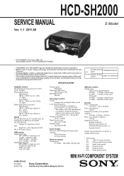
E Model
Ver. 1.1 2011.09
• HCD-SH2000 is the tuner, USB, CD and amplifier section in FST-SH2000/LBT-SH2000.
• "WALKMAN" and "WALKMAN" logo are registered trademarks of Sony Corporation. • MPEG Layer-3 audio coding technology and patents licensed from the objective lens surface on the Optical Pick-up Name
KHM-313CAB...
Service Manual - Page 2
...-63Trd are examples of a passive VOM that have an accurate low-voltage scale. HCD-SH2000
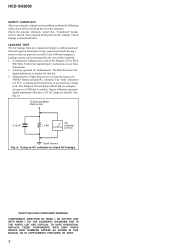
SAFETY CHECK-OUT After correcting the original service problem, perform the following safety check ...Fig.
A.
The Data Precision 245 digital multimeter is suitable for AC leakage. REPLACE THESE COMPONENTS WITH SONY PARTS WHOSE PART NUMBERS APPEAR AS SHOWN IN THIS MANUAL OR IN SUPPLEMENTS PUBLISHED...
Service Manual - Page 3
...Printed Wiring Boards - VOLUME Board 45 5-31. Schematic Diagram - AUDIO-IN ...HCD-SH2000
TABLE OF CONTENTS
1. Block Diagram - EXPLODED VIEWS 6-1. Block Diagram - Schematic Diagram - MAIN Board (3/4) (Suffix 12) - .. 30 5-16. Schematic Diagram - DAMP Board (4/4 42 5-28. DAMP Board (Component Side 37 5-23. VOLUME Board 46 5-32. MIC Board 52
6. Printed Wiring...
Service Manual - Page 4
... board is defective, exchange the entire MD (AU) ASSY.
4 PART No. MP3 audio tracks must be in MPEG 1 Audio Layer 3 format.
2) A logical format of files and folders on CD-ROMs... by the charged electrostatic load, etc.
HCD-SH2000
Ver. 1.1
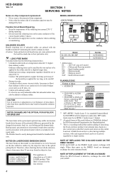
SECTION 1 SERVICING NOTES
Notes on chip component replacement • Never reuse a disconnected chip component. • Notice that the minus side...
Service Manual - Page 5
... MAIN board (Suffix-12) are damaged, remove IC103 and C242 (Combination: TYPE B) and replace with single.
HCD-SH2000
5
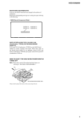
CD mechanism block bottom view - Repair after distinguishing each type set , the MAIN board has been changed in ... a set
referring to the following. - disc
- MAIN Board (Component Side) - Please rotate the pully in the midway of the arrow and eject the disc.
Service Manual - Page 7
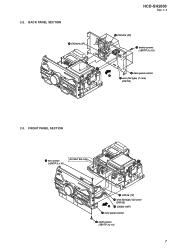
BACK PANEL SECTION
4 CN1404 (3P)
HCD-SH2000
Ver. 1.1
3 CN1405 (3P)
1 twelve screws (+BVTP 3 x 10)
6 back panel section 5
2 wire (flat type) (7 core) (CN703)
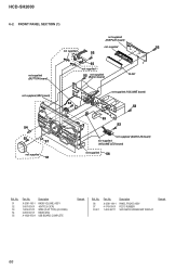
2-3. 2-2. FRONT PANEL SECTION
1 two screws (+BVTP 3 x10)
(for SAF, EA only)
3 CN106 (7P) 4 wire (flat type) (23 core)
(CN105) 6 5 CN300 (14P) 7 front panel section
2 eight screws (+BVTP 3 x10)
7
Service Manual - Page 8
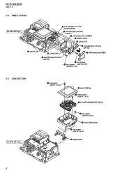
... type) (24 core) (CN101) qd shield plate bottom DMB21 qs DMB21 board
6 CN701 (7P)
9 CN201 (6P)
q; HCD-SH2000
Ver. 1.1
2-4. CN302 (3P)
qa wire (flat type) (13 core) (CN700)
5 wire (flat type) (13 core) (CN702)
2 3 Shield plate top DMB21
4 four screws 1 four screws (+BV3 (3-CR))
(+BVTP 3 x10)
2-5. DMB21 BOARD
(for SAF, EA only)
1 two screws...
Service Manual - Page 9
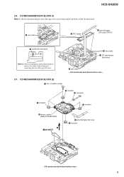
CD mechanism deck block bottom view -
2-7. HCD-SH2000
2-6. Note 2: When assembling the optical pick-up block, solder the short-land.
2 two claws
4 FFC holder
6 wire (flat type) (24 core) (CN101)
5 Solder the short-land. CD mechanism deck block bottom view -
9 CD MECHANISM DECK BLOCK (2)
1 four insulator screws
5 insulator 3 connector
5 insulator
5 ...
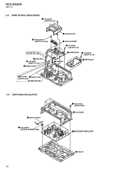
Service Manual - Page 10
...
(SCREW, WASHER (M3))
1 four screws (+BV3 (3-CR))
2 sub chassis
5SWITCHING REGULATOR
6 chassis
10 MAIN board
qdone screw qfstopper wiring (+BVTP 3x10)
(for SAF, EA only)
6 CN2 (9P) qa one screw
(+BVTP 3 x 10) qsstopper wiring
2 bracket tunnel
4 heat sink DAMP
5 six screws (+BVTP 3 x 10)
8 DAMP board 9 six screws (+BVTP 3 x 10)
7 CN3 (6P)
q; HCD-SH2000
Ver. 1.1
2-8.
Service Manual - Page 19

...AUDIO (DIGITAL)
• Abbreviation E2 : 120 V AC area in μF unless otherwise noted. (p: pF)
50 WV or less are not indicated except for electrolytics and tantalums. • All resistors are critical for Printed Wiring Boards and Schematic Diagrams
Note on Printed Wiring Board:
• X : parts extracted from the component... model
HCD-SH2000
19
19
HCD-SH2000
Ver. 1.1 Line. • Voltage ...
Service Manual - Page 20

... (Page 47)
VOLUME
A BOARD CN1000 (Page 45)
AUDIO-IN
H BOARD NO1200 (Page 51)
11 (11)
CN704
CN705
(CHASSIS)
G
DAMP BOARD CN1400 (Page 37)
B
DAMP BOARD CN1401 (Page 37)
J
HCD-SH2000
20
20
Note: Refer to distinguish SUFFIX-11 and SUFFIX-12. F
-&%
41&",&3
3
G
H
I
F700
3
1
3
1
J500
MAIN BOARD
(Component side)
DMB21
I BOARD CN4604 (Page 32)
DMB21...
Service Manual - Page 22

...: TYPE A). PRINTED WIRING BOARDS -
MAIN board...AUDIO-IN
H BOARD NO1200 (Page 51)
12 (12)
(CHASSIS)
G
DAMP BOARD CN1400 (Page 37)
B
DAMP BOARD CN1401 (Page 37)
J
HCD-SH2000
Note 1: Refer to the servicing notes "MAIN BOARD DISCRIMINATION" (page 5) for Circuit Boards Location. • : Uses unleaded solder.
1
2
3
4
5
6
7
8
9
10
11
12
13
14
15
A
MAIN BOARD (Component...
Service Manual - Page 32

... 2: When the MS-214 board is damaged, exchange the entire mounted board. PRINTED WIRING BOARDS - DMB21 BOARD (Component Side) - • See page 14 for Circuit Boards Location. • : Uses unleaded solder.
1
2
3
4
5
6
7
8
9
10
11
12
13
14
15
A B C D E F G H I
J
HCD-SH2000
DMB21 BOARD (Component side) NC
(CHASSIS)
MAIN
I BOARD
CN702 (Page 20) (Suffix 11) (Page 22) (Suffix...
Service Manual - Page 37
...WIRING BOARDS - MAIN
G BOARD CN102 (Page 20) (Suffix 11) (Page 22) (Suffix 12)
MAIN
B BOARD CN100 (Page 20) (Suffix 11) (Page 22) (Suffix 12)
12 (12)
SWITCHING REGULATOR
37
37
HCD-SH2000
Ver. 1.1
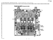
15 DAMP BOARD (Component...
10
11
12
13
14
A B C D E F G H I
J
HCD-SH2000
DAMP BOARD (Component side)
LOW SPEAKER
(CHASSIS)
C1665
ET1400
L
R
,0PE'A1&E 8SE 4Ÿ
TB1400
Q1454 R1645
...
Service Manual - Page 49
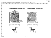
PRINTED WIRING BOARDS - HCD-SH2000
Ver. 1.1
5-34. VOLUME LED, BUTTON LED AND TUNER BOARD - • See page 14 for Circuit Boards Location. • : Uses unleaded solder.
1
2
3
4
5
6
7
8
9
10
11
12
13
14
15
A
B
TUNER BOARD (Component side)
TUNER BOARD (Conductor side)
ANTENNA
FM/AM
C
3
1
C1620 C1619
CN1602
D1601
D1603
C1622
C1621
FL1601
D
R1605 R1607
D1602
...
Service Manual - Page 51

...-L 6 JL1204
C1202 220p
R1202 33k
WHT
A-GND
7 JL1205
PC-L 8 JL1206
C1203 220p
R1203 33k R1207 27k
C1205 0.47
C1207 1000p
D1201 MC2840-T112-1
PC
RED
G
H
H
I
I
J
HCD-SH2000
J
51
51 AUDIO-IN BOARD - • See page 14 for Circuit Boards Location.
5-37. •
: Uses unleaded solder.
5-36. AUDIO-IN BOARD -
PRINTED WIRING BOARDS - SCHEMATIC DIAGRAM -
Service Manual - Page 64

... terminal Not used O Component video (Pr/Cr) signal output terminal Not used
- Not used
- Power supply terminal (+3.3V) I Limit detection switch input terminal O L/R sampling clock signal output to the A/D converter and D/A converter O Audio data output to the D/A converter
- Audio D/A converter reference voltage terminal I External capacitor connecting terminal
- HCD-SH2000
Pin No. 69...
Service Manual - Page 65
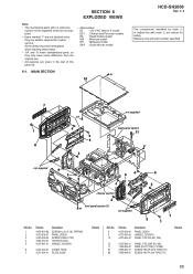
MAIN SECTION
#1
10
HCD-SH2000
Ver. 1.1
The components identified by mark 0 or dotted line with no reference
number in the exploded views ...PANEL, SIDE A HANDLE, COVER A PANEL, TOP (E2, E51, MX)
10
4-275-642-11 PANEL, TOP (SAF, EA, MY)
11
1-828-944-51 WIRE (FLAT TYPE) (7 CORE)
#1
7-685-647-71 SCREW +BVTP 3X10 TYPE2 IT-3
#2
7-685-646-71 SCREW +BVTP 3X8 TYPE2 IT-3
Remark
65 No.
1...
Service Manual - Page 66
HCD-SH2000
6-2.
Description
X-2581-184-1 PANEL FRONT, ASSY 4-176-619-01 FOOT, RUBBER 1-483-367-11 VACUUM FLUORESCENT DISPLAY
Remark
66... board)
FL901
not supplied (MIC board)
54 52
57
not supplied
51
not supplied (VOLUME board)
52 52
53 52
not supplied (AUDIO-IN board)
not supplied (VOLUME LED board)
not supplied
56
Ref. Description
X-2581-185-1 3-087-053-01 1-829-021-51 2-895...
Service Manual - Page 70

...HCD-SH2000
Ver. 1.1 AUDIO-IN BUTTON
BUTTON LED
SECTION 7 ELECTRICAL PARTS LIST
Note: • Due to standardization, replacements in
the parts list may have some difference from the parts specified in the diagrams or the components...
• CAPACITORS uF: μF
• COILS uH: μH
The components identified by reference number, please include the board name.
• Abbreviation ...
Similar Questions

Speaker Wire Connector
looking for part number: 1-839-129-11 and 1-839-128-2
looking for part number: 1-839-129-11 and 1-839-128-2
(Posted by Crsj1981 2 years ago)

How Much Does A 2016 Model Number Had Sh2000 Stereo System Cost With The 2 15 In
inch subwoofers
inch subwoofers
(Posted by Anonymous-160594 7 years ago)

What Type Of Speaker Cable For Sony Stereo Hcd-zx9
what type of speaker cable for sony stereo hcd-zx9 to use for it
what type of speaker cable for sony stereo hcd-zx9 to use for it
(Posted by Minouchie 8 years ago)

How Do I Turn Off The Child Lock On The Sony Hcd-sh2000 Stereo System
(Posted by blueyez5808 10 years ago)
Where Can I Get A Replacement Remote For My Sony Hcd-241 Stereo System?
Where can I get a replacement remote for my Sony HCD-241 Stereo system?
Where can I get a replacement remote for my Sony HCD-241 Stereo system?
(Posted by jthole 11 years ago)