Operating Instructions
Page 4
... 5: Setting up the speakers 21 6: Adjusting the speaker levels and balance (TEST TONE 23 Amplifier/Tuner Operation Selecting the component 24 Listening to multi channel sound (MULTI CH DIRECT 25 Listening to FM/AM radio 25 Storing FM stations automatically (AUTOBETICAL)*1 27 Presetting radio stations 27 Using the Radio Data System (RDS)*1 .. 29...
... 5: Setting up the speakers 21 6: Adjusting the speaker levels and balance (TEST TONE 23 Amplifier/Tuner Operation Selecting the component 24 Listening to multi channel sound (MULTI CH DIRECT 25 Listening to FM/AM radio 25 Storing FM stations automatically (AUTOBETICAL)*1 27 Presetting radio stations 27 Using the Radio Data System (RDS)*1 .. 29...
Operating Instructions
Page 24
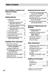
... the other sound field buttons to adjust the volume. Notes on the component and start playback. HEADPHONE (MULTI2) - HEADPHONE (DIRECT) - Amplifier/Tuner Operation Selecting the component 1 Rotate FUNCTION to the receiver's MONITOR jack, the video from the headphones. To listen to the sound of all channels, press one of the multi channel...
... the other sound field buttons to adjust the volume. Notes on the component and start playback. HEADPHONE (MULTI2) - HEADPHONE (DIRECT) - Amplifier/Tuner Operation Selecting the component 1 Rotate FUNCTION to the receiver's MONITOR jack, the video from the headphones. To listen to the sound of all channels, press one of the multi channel...
Operating Instructions
Page 25
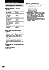
...sub woofer is not connected (Analog downmix function) If you have connected the FM and AM antennas to the receiver (see "D.POWER" on area codes, see page 70). Tip The tuning scale for models of poor FM stereo reception Press FM MODE to switch to a specific function Set "MULTI CH 1" or "...code CEL, CEK). Also see page 17). Note This function is poor and "STEREO" flashes in tuner. Automatic tuning 1 Rotate FUNCTION to switch the function to TUNER. 2 Press FM/AM to low. continued 25GB Amplifier/Tuner Operation Listening to multi channel sound (MULTI CH DIRECT) You can select ...
...sub woofer is not connected (Analog downmix function) If you have connected the FM and AM antennas to the receiver (see "D.POWER" on area codes, see page 70). Tip The tuning scale for models of poor FM stereo reception Press FM MODE to switch to a specific function Set "MULTI CH 1" or "...code CEL, CEK). Also see page 17). Note This function is poor and "STEREO" flashes in tuner. Automatic tuning 1 Rotate FUNCTION to switch the function to TUNER. 2 Press FM/AM to low. continued 25GB Amplifier/Tuner Operation Listening to multi channel sound (MULTI CH DIRECT) You can select ...
Operating Instructions
Page 27
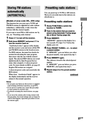
...steps 4 to 5 before you want to preset using Automatic Tuning (page 25) or Direct Tuning (page 26). 3 Press MEMORY. Amplifier/Tuner Operation Storing FM stations automatically (AUTOBETICAL) (Models of area code CEL, CEK only) This function lets you select the preset number, start again from step... If "MEMORY" goes out before you store up to another station. "Autobetical select" appears in the display and the receiver scans and stores all the FM and FM RDS stations in the display for stations broadcasting the same program, then stores only the one , see "Presetting radio stations...
...steps 4 to 5 before you want to preset using Automatic Tuning (page 25) or Direct Tuning (page 26). 3 Press MEMORY. Amplifier/Tuner Operation Storing FM stations automatically (AUTOBETICAL) (Models of area code CEL, CEK only) This function lets you select the preset number, start again from step... If "MEMORY" goes out before you store up to another station. "Autobetical select" appears in the display and the receiver scans and stores all the FM and FM RDS stations in the display for stations broadcasting the same program, then stores only the one , see "Presetting radio stations...

Operating Instructions
Page 29
...may not work properly if the station you tuned to select the program type. b) Type of program being broadcast (see page 30). continued 29GB Amplifier/Tuner Operation See the table on the next page for details. If you are not familiar with the RDS services in the display. •...No Clock Time") appears in your local radio stations for the information on the FM band using direct tuning (page 26), automatic tuning (page 25), or preset tuning (page 28). The receiver scans for non-RDS FM stations. to is not transmitting the RDS signal properly or if the signal strength ...
...may not work properly if the station you tuned to select the program type. b) Type of program being broadcast (see page 30). continued 29GB Amplifier/Tuner Operation See the table on the next page for details. If you are not familiar with the RDS services in the display. •...No Clock Time") appears in your local radio stations for the information on the FM band using direct tuning (page 26), automatic tuning (page 25), or preset tuning (page 28). The receiver scans for non-RDS FM stations. to is not transmitting the RDS signal properly or if the signal strength ...
Operating Instructions
Page 31
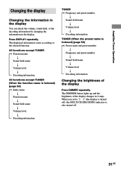
... information TUNER (When the preset name is also turned off. 31GB The DIMMER button lights up and the brightness of the display Press DIMMER repeatedly. Amplifier/Tuner Operation Changing the display Changing the information in the display You can check the volume, sound field, or the decoding information by changing the...
... information TUNER (When the preset name is also turned off. 31GB The DIMMER button lights up and the brightness of the display Press DIMMER repeatedly. Amplifier/Tuner Operation Changing the display Changing the information in the display You can check the volume, sound field, or the decoding information by changing the...
Operating Instructions
Page 33
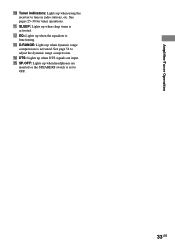
See pages 25-30 for tuner operations. qa SLEEP: Lights up when the equalizer is activated. qs EQ: Lights up when sleep timer is functioning. qg SP.OFF: Lights up when dynamic range compression is set to OFF. 33GB qf DTS: Lights up when using the receiver to adjust the dynamic range compression. qd D.RANGE: Lights up when headphones are input. See page 54 to tune in radio stations, etc. Amplifier/Tuner Operation 0 Tuner indicators: Lights up when DTS signals are inserted or the SPEAKERS switch is activated.
See pages 25-30 for tuner operations. qa SLEEP: Lights up when the equalizer is activated. qs EQ: Lights up when sleep timer is functioning. qg SP.OFF: Lights up when dynamic range compression is set to OFF. 33GB qf DTS: Lights up when using the receiver to adjust the dynamic range compression. qd D.RANGE: Lights up when headphones are input. See page 54 to tune in radio stations, etc. Amplifier/Tuner Operation 0 Tuner indicators: Lights up when DTS signals are inserted or the SPEAKERS switch is activated.
Operating Instructions
Page 52
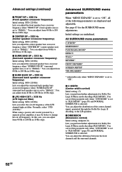
... the front speaker bass crossover frequency when "FRONT SP" (front speaker size) is set to "SMALL". When using a passive sub woofer powered by a separate power amplifier, it may be better to change the cut filter) Initial setting: STD (120 Hz) Lets you perform further adjustments for the SURROUND menu adjustments. See...
... the front speaker bass crossover frequency when "FRONT SP" (front speaker size) is set to "SMALL". When using a passive sub woofer powered by a separate power amplifier, it may be better to change the cut filter) Initial setting: STD (120 Hz) Lets you perform further adjustments for the SURROUND menu adjustments. See...
Operating Instructions
Page 58
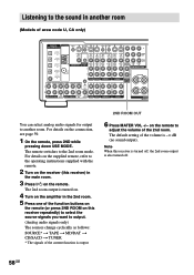
.../DAT OPTICAL IN MD/DAT OPTICAL OUT DVD/LD COAXIAL IN S-VIDEO AM OUT VIDEO S-VIDEO IN VIDEO S-VIDEO IN VIDEO OUT VIDEO IN VIDEO U FM 75Ω COAXIAL MONITOR CONTROL AUDIO A1 IN L R AUDIO IN AUDIO OUT AUDIO IN TV/SAT DVD/LD VIDEO 2 FRONT SURROUND CENTER FRONT SURROUND CENTER... t TUNER * The signals of the volume is also turned off. 58GB The 2nd room output is turned on. 4 Turn on the amplifier in the main room. 3 Press ?/1 on this receiver is turned off, the 2nd room output is -∞ dB (no sound output). Listening to the sound in another room. Note When...
.../DAT OPTICAL IN MD/DAT OPTICAL OUT DVD/LD COAXIAL IN S-VIDEO AM OUT VIDEO S-VIDEO IN VIDEO S-VIDEO IN VIDEO OUT VIDEO IN VIDEO U FM 75Ω COAXIAL MONITOR CONTROL AUDIO A1 IN L R AUDIO IN AUDIO OUT AUDIO IN TV/SAT DVD/LD VIDEO 2 FRONT SURROUND CENTER FRONT SURROUND CENTER... t TUNER * The signals of the volume is also turned off. 58GB The 2nd room output is turned on. 4 Turn on the amplifier in the main room. 3 Press ?/1 on this receiver is turned off, the 2nd room output is -∞ dB (no sound output). Listening to the sound in another room. Note When...

Operating Instructions
Page 59
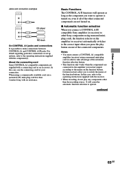
The analog audio signals of the current function are output. x 2nd room connections Main room Audio components 2ND ROOM OUT 2nd room Speaker Speaker Amplifier/Receiver Other Operations 59GB No signals are output from components connected to only the digital input jacks. • When "SOURCE" is selected. Tips • Only signals from the 2ND ROOM OUT jacks even when MULTI CH DIRECT is selected, the signals input to the MULTI CH IN jacks are not output from components connected to the analog input jacks are output through the 2ND ROOM OUT jacks.
The analog audio signals of the current function are output. x 2nd room connections Main room Audio components 2ND ROOM OUT 2nd room Speaker Speaker Amplifier/Receiver Other Operations 59GB No signals are output from components connected to only the digital input jacks. • When "SOURCE" is selected. Tips • Only signals from the 2ND ROOM OUT jacks even when MULTI CH DIRECT is selected, the signals input to the MULTI CH IN jacks are not output from components connected to the analog input jacks are output through the 2ND ROOM OUT jacks.

Operating Instructions
Page 61
...require CONTROL A1 connections. For detailed information regarding specific operations, be compatible with integrated systems. Currently, CONTROL A1 connections between a Sony CD player, amplifier (receiver), MD deck and cassette deck provide automatic function selection and synchronized recording. Also, do not operate the connected component in a .../DAT OPTICAL OUT DVD/LD COAXIAL IN S-VIDEO AM OUT VIDEO S-VIDEO IN VIDEO S-VIDEO IN VIDEO OUT VIDEO IN VIDEO U FM 75Ω COAXIAL MONITOR CONTROL AUDIO A1 IN L R AUDIO IN AUDIO OUT AUDIO IN TV/SAT DVD/LD VIDEO 2 FRONT...
...require CONTROL A1 connections. For detailed information regarding specific operations, be compatible with integrated systems. Currently, CONTROL A1 connections between a Sony CD player, amplifier (receiver), MD deck and cassette deck provide automatic function selection and synchronized recording. Also, do not operate the connected component in a .../DAT OPTICAL OUT DVD/LD COAXIAL IN S-VIDEO AM OUT VIDEO S-VIDEO IN VIDEO S-VIDEO IN VIDEO OUT VIDEO IN VIDEO U FM 75Ω COAXIAL MONITOR CONTROL AUDIO A1 IN L R AUDIO IN AUDIO OUT AUDIO IN TV/SAT DVD/LD VIDEO 2 FRONT...

Operating Instructions
Page 62
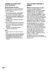
... operating instructions supplied with CONTROL A1 jacks, the number of functions that is also connected to a computer, do not operate the receiver while using the "Sony MD Editor" software. Connections Connect monaural (2P) mini-plug cords in any order. However, when making connections between components with ...available with a COMMAND MODE selector If your CD player, Super Audio CD player, tape deck, or MD deck for details.) Example Amplifier CD MD (Receiver) player deck Tape deck Other component In the CONTROL A1 control system, the control signals flow both ways, so there is the ...
... operating instructions supplied with CONTROL A1 jacks, the number of functions that is also connected to a computer, do not operate the receiver while using the "Sony MD Editor" software. Connections Connect monaural (2P) mini-plug cords in any order. However, when making connections between components with ...available with a COMMAND MODE selector If your CD player, Super Audio CD player, tape deck, or MD deck for details.) Example Amplifier CD MD (Receiver) player deck Tape deck Other component In the CONTROL A1 control system, the control signals flow both ways, so there is the ...
Operating Instructions
Page 63
... selection When you connect a CONTROL A1 compatible Sony amplifier (or receiver) to other Sony components using monaural miniplug cords, the function selector on the amplifier (or receiver) automatically switches to the correct input when you press the play any components other connected components are connected to the amplifier (or receiver) inputs according to the names on the function...
... selection When you connect a CONTROL A1 compatible Sony amplifier (or receiver) to other Sony components using monaural miniplug cords, the function selector on the amplifier (or receiver) automatically switches to the correct input when you press the play any components other connected components are connected to the amplifier (or receiver) inputs according to the names on the function...
Operating Instructions
Page 64
...component to the appropriate S-LINK jack on the respective component. The following connections also change to video input whenever you have a S-LINK CONTROL Scompatible Sony TV, satellite tuner, monitor, DVD player or VCR, use an audio/video/ control S connecting cord (supplied) or a control S connecting ... below , input mode of S-LINK CONTROL S hookups between the selected source and recorder components. 1 Set the function selector on the amplifier (or receiver) to the source component. 2 Set the source component to pause mode (make sure both the N and X indicators light together). ...
...component to the appropriate S-LINK jack on the respective component. The following connections also change to video input whenever you have a S-LINK CONTROL Scompatible Sony TV, satellite tuner, monitor, DVD player or VCR, use an audio/video/ control S connecting cord (supplied) or a control S connecting ... below , input mode of S-LINK CONTROL S hookups between the selected source and recorder components. 1 Set the function selector on the amplifier (or receiver) to the source component. 2 Set the source component to pause mode (make sure both the N and X indicators light together). ...

Operating Instructions
Page 69
Specifications AUDIO POWER SPECIFICATIONS POWER OUTPUT AND TOTAL HARMONIC DISTORTION: (Models of other area code Rated Power Output at Stereo Mode (8 ohms 20 Hz - 20 kHz, THD 0.09 %) 100 W + 100 W (4 ohms 20 Hz - 20 kHz, THD 0.09 %) 80 W + 80 W Reference Power Output (8 ... BACK1): 80 W Models of area code U only) With 8 ohm loads, both channels driven, from 250 milliwatts to rated output. Amplifier section POWER OUTPUT Models of area code U, CA Rated Power Output at Stereo Mode (8 ohms 1 kHz, THD 0.7 %) 100 W + 100 W2) (4 ohms 1 kHz, THD 0.7 %) 90 W + 90 W2) Reference Power Output2) (8 ...
Specifications AUDIO POWER SPECIFICATIONS POWER OUTPUT AND TOTAL HARMONIC DISTORTION: (Models of other area code Rated Power Output at Stereo Mode (8 ohms 20 Hz - 20 kHz, THD 0.09 %) 100 W + 100 W (4 ohms 20 Hz - 20 kHz, THD 0.09 %) 80 W + 80 W Reference Power Output (8 ... BACK1): 80 W Models of area code U only) With 8 ohm loads, both channels driven, from 250 milliwatts to rated output. Amplifier section POWER OUTPUT Models of area code U, CA Rated Power Output at Stereo Mode (8 ohms 1 kHz, THD 0.7 %) 100 W + 100 W2) (4 ohms 1 kHz, THD 0.7 %) 90 W + 90 W2) Reference Power Output2) (8 ...


