Sony STR-K1500 Support Question
Sony STR-K1500 Support Question
Find answers below for this question about Sony STR-K1500 - Receiver Component For Ht-ddw1500.Need a Sony STR-K1500 manual? We have 1 online manual for this item!
Question posted by okmrfixit on December 7th, 2012
Y Does My Amplifier Go Into Protection Sometimes
Y DOES MY AMPLIFIER GO INTO PROTECTION SOMETIMES, IT DOES NOT MATTER IF ANYTHING IS CONNECTED OR NOT, AND SOMETHIMES IT WORKS PERFECTLY,
Current Answers
Related Sony STR-K1500 Manual Pages
Service Manual - Page 1

...
Home Audio Division Published by Sony Techno Create Corporation Inputs (Analog)
MULTI CH IN, SA-CD/CD, MD/TAPE, DVD, VIDEO 1, 2, 3
Sensitivity: 800 mV Impedance: 50 kohms
Inputs (Digital) DVD (Coaxial)
VIDEO 1, 2 (Optical)
Sensitivity: - SERVICE MANUAL
Ver. 1.1 2006.05
STR-K1500
E Model Australian Model
• STR-K1500 is the tuner and the amplifier section in HT-DDW1500. "Dolby...
Service Manual - Page 2

...for example, "Models of area code AA only".
2 Video section Inputs/Outputs
Video:
1 Vp-p, 75 ohms
COMPONENT VIDEO: Y: 1 Vp-p, 75 ohms
PB/CB/B-Y: 0.7 Vp-p, 75 ohms
PR/CR/R-Y: 0.7 Vp-p, 75 ... 8.0 kg
Design and specifications are clearly indicated in any AM station, turn off the receiver. Rear Panel -
STR-K1500
Ver. 1.1
AM tuner section Tuning range
Models of area code SP, SP6, AUS With...
Service Manual - Page 3
STR-K1500
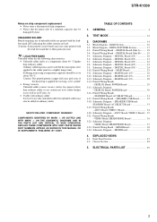
Notes on chip component replacement • Never reuse a disconnected chip component. • Notice that the minus side of ...regulator should be set to the solder joint for too long, so be added to ordinary solder. SAFETY-RELATED COMPONENT WARNING!! TABLE OF CONTENTS
1. DIGITAL Board (2/5 21 3-7. Schematic Diagram - Schematic Diagram - Front Panel Section...
Service Manual - Page 4

STR-K1500
Receiver
Front panel
12
SECTION 1 GENERAL
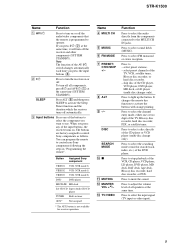
This section is decoded. Name
Function
A ?/1
Press to select the tuning mode . D MULTI CHANNEL Lights up when multi DECODING lamp channel audio is extracted from the components connected to select A.F.D. H MASTER VOLUME
Turn to scan a station.
mode. P TUNING MODE Press to turn the speakers and sub woofers on or...
Service Manual - Page 5

... not function for DTS format signals or for signals with a sampling frequency of more than 48 kHz. STR-K1500
About the indicators on the display
1 23 4
5
67
8
9
SW LFE SP ;DIGITAL EX ...DTS 96 kHz/24 bit signals. However, this indicator do not light up when the receiver is connected. PRO LOGIC" lights up when the audio signal is output from the SUB WOOFER jack.
"; Name
A SW B LFE
C...
Service Manual - Page 6

... compression is activated.
Lights up when a memory function, such as Preset Memory, etc., is activated.
STR-K1500
Name
I MEMORY J Preset
station indicators K D.RANGE L HDMI* M COAX
N OPT
O SLEEP
Function
Lights up when using the receiver to show how the receiver downmixes the source sound.
Flashes when you have preset. in radio stations you select "HDMI...
Service Manual - Page 7
... deck or CD player, etc.
SURROUND BACK
L
L
+
-
+
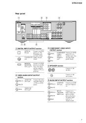
- B VIDEO/AUDIO INPUT/OUTPUT section
AUDIO IN/ White (L) OUT jack
Red (R)
Connects the video and audio jacks of loud
jack
sound. STR-K1500
Rear panel
1
23
4
DIGITAL OPTICAL
VIDEO 1 IN
VIDEO 2 IN
ANTENNA AM
DVD IN
VIDEO 2 IN MONITOR OUT
COMPONENT VIDEO ASSIGNABLE
Y
ASSIGNABLE
HDMI
MONITOR
PB/CB
/B-Y
PR/CR...
Service Manual - Page 8

... qg qh
8 STR-K1500
F D-LIGHT SYNC OUT section
D-LIGHT Connects to the AM loop antenna supplied with this receiver . jack
G ANTENNA section
FM ANTENNA
Connects to a TV monitor. b)Except for models of area code MX, E51 . You can use the supplied remote RM-AAP013 to operate the receiver and to control the Sony audio/video components that the...
Service Manual - Page 9
...
AUX*
Not assigned
* The AUX button is programmed to operate. STR-K1500
Name
Function
A AV ?/1
Press to turn on or off . Press to select the input signal (TV input or video input).
9 Press to turn the receiver on or off the audio/video components that the remote is not available for search (track, index, etc...
Service Manual - Page 10

... Press to select information displayed on -screen guide of the receiver. Press to - Press to - Then, use the control...disc recorder, hard disc recorder, or PSX. (Also starts recording with components in the forward/
backward direction of the CD player, VCD player, ...TV volume level. R TV VOL
+a)/- Press to select preset TV channels. STR-K1500
Name
N AMP MENU
O AUTO CAL P WIDE Q TV CH +a)/-
...
Service Manual - Page 11

...turn the TV on the component, the above explanation is intended... work depending on the remote are not available for receiver... operation. Press to - JUMP/TIME
Press to select A.F.D. Use the tactile dots as an example only. MOVIE
Press to Multiplex, Bilingual or Multi channel TV sound of the DVD player or Blu-ray disc recorder. AUDIO...STR-K1500
Name
Function
wj TUNING +/-
Service Manual - Page 13
... jog, there will be test tone sound output from front left speaker of test tone)
STR-K1500 13 "AD[]-[]xxx" xxx = 0 to turn on the main power.
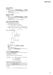
2. VACS CONTROL...receiver and AUTO CAL microphone. "DCAC[]FTM" appears. When power off : Press the three buttons TUNING + + MOVIE + ?/1 . "VACS OFF" appears. (10 second)
SWAP ALL MODE Procedure:
1. DCAC AUTO CAL MIC board Checking Connect...
Service Manual - Page 14

... on the pattern face side seen from the side which enables seeing. STR-K1500
Ver. 1.1
SECTION 3 DIAGRAMS
THIS NOTE IS COMMON FOR PRINTED WIRING ...:
• X : parts extracted from the component side.
• a : Through hole.
• f : internal component.
•
: Pattern from the pattern face are omitted.
14
Note: The components identified by mark 0 or dotted line with part...
Service Manual - Page 16

...
R-CH TUNER +10V
IC1301 DIGITAL AUDIO I/F RECEIVER
XMCK 20 5 DIN2
3 DIN0
4 DIN1
CK OUT 13
BCK 14
LRCK 15
35 DO
DATAO 16
36 DI
AUDIO 24
38 CLK
37 CE
34 ERROR...LIGHT
SYNC-OUT
J309 AUDIO OUT SUB WOOFER
IC1131 EEPROM
SDA SCL
5
6
29 30
70
Q560
RELAY DRIVE
RY560
COMPONENT VIDEO
J301 (1/2)
VIDEO 2 IN
Y PB/CB/B-Y PR/CR/R-Y
Y
DVD IN
PB/CB/B-Y
PR/CR/R-Y
STR-K1500
24
3 CH1 IN2...
Service Manual - Page 17

...SYSTEM CONTROL IC1101(2/2)
X0 X1 A/D1 A/D2 ADCC
STR-K1500
J2000 AUTO CAL MIC
82 83
39
40
38...PROTECT
Q655,656 CURRENT DETECT
Q640 AF POWER PROTECT
Q505,506 CURRENT DETECT
Q540 AF POWER PROTECT
Q535,536 CURRENT DETECT
Q580 AF POWER PROTECT
D721 Q722,723,725 PROTECT...IC102 REMOTE 1 CONTROL RECEIVER
IC1111 1 RESET 2
+3.3V +2.5V
+5V
TUNER +10V RELAY +B AUDIO +7V
AUDIO +5V
AUDIO -7V +3.3V
(...
Service Manual - Page 36

.../ CB / B-Y PR / CR / R-Y
DVD
VIDEO 2
VIDEO IN
VIDEO IN
VIDEO OUT
VIDEO 1
MONITOR VIDEO IN VIDEO OUT
7
8
MONITOR OUT
VIDEO 2 IN DVD IN
COMPONENT VIDEO
ASSIGNABLE
9
10
C
F
DIGITAL
BOARD
D
CNS509
(Page 19)
E
9
16
IC203
8
1
3
1
1 3
3 6
1 1
IC804
IC304
IC807
3
1
S
MAIN... D203 C-3 D204 D-3
IC203 C-4 IC304 D-5 IC804 E-4 IC807 E-5
STR-K1500
36
36 STR-K1500
3-21.
Service Manual - Page 47

...-043-1 FRONT PANEL ASSY (E51, MX)
4-977-358-01 CUSHION 3-087-053-01 +BVTP2.6 (3CR)
Ref. E51 : Chilean and Peruvian models. FRONT PANEL SECTION
STR-K1500
Ver. 1.1
The components identified by mark 0 or dotted line with part number specified. not supplied
c not supplied not supplied
6
not supplied
d
a
b
9
6 6
not supplied
not supplied
6
7
6
#1
8
5
3
#1
2
supplied with...
Service Manual - Page 49

.... Ref. SP : Singapore model. uPD. . : µPD. . No. SECTION 5 ELECTRICAL PARTS LIST
STR-K1500
Ver. 1.1 AC SELECT ADCC
DIGITAL
NOTE: • Due to standardization, replacements in the
parts list may be ...µF
• Items marked "*" are not stocked since they
are in the diagrams or the components used on the set. • -XX and -X mean standardized parts, so they may have...
Service Manual - Page 60

...5%
0 R764 0 R765 0 R766 0 R767 0 R768
1-249-399-11 CARBON
33
5%
1-249-399-11 CARBON
33
5%
1-234-182-11 ENCAPSULATED COMPONENT
1-249-393-11 CARBON
10
5%
1-249-389-11 CARBON
4.7
5%
R769 0 R771
R772 R773 R775
1-247-847-91 CARBON 1-240-855-81 CARBON 1-...1uF 10% 50V 2200uF 20% 25V 1000uF 20% 25V 0.1uF 10% 50V
60 No. STR-K1500
Ver. 1.1
MAIN POWER SPEAKER C/SB STANDBY
Ref. No. Part No.
Service Manual - Page 61

..., MONITOR/VIDEO OUT)
J301 1-816-592-11 JACK, PIN 9P (COMPONENT VIDEO)
< RESISTOR >
R200 R201 R218
1-247-804-11 CARBON 1-247-804-11 CARBON 1-247-804-11 CARBON
75
5% 1/4W
75
5% 1/4W
75
5% 1/4W
61 C921 C924 C950
Part No. No.
STR-K1500
STANDBY VIDEO
Ref.
Description
1-127-888-11 CERAMIC 1-126-960...
Similar Questions

What Can Do When My Amplifier Is No Turn On?
(Posted by Anonymous-171736 1 year ago)

One Subwoofer Dont Play
Power on both subwoofers but only one sub giving me volume str k1500 sony
Power on both subwoofers but only one sub giving me volume str k1500 sony
(Posted by masememzi 2 years ago)

My Str-k1500 Has Stopped Producing Sound Or Audio
(Posted by johnmatudama 2 years ago)

Sony Receiver Digital A/v Control Center Str K840p 5.1 Surround Sound Speakers
rl and surround sound speakers wont work at the same time setup
rl and surround sound speakers wont work at the same time setup
(Posted by greesamu 10 years ago)
Dispay Flashes Protection,and Unit Does Not Work Sony Str-k502
(Posted by thedawson25 12 years ago)